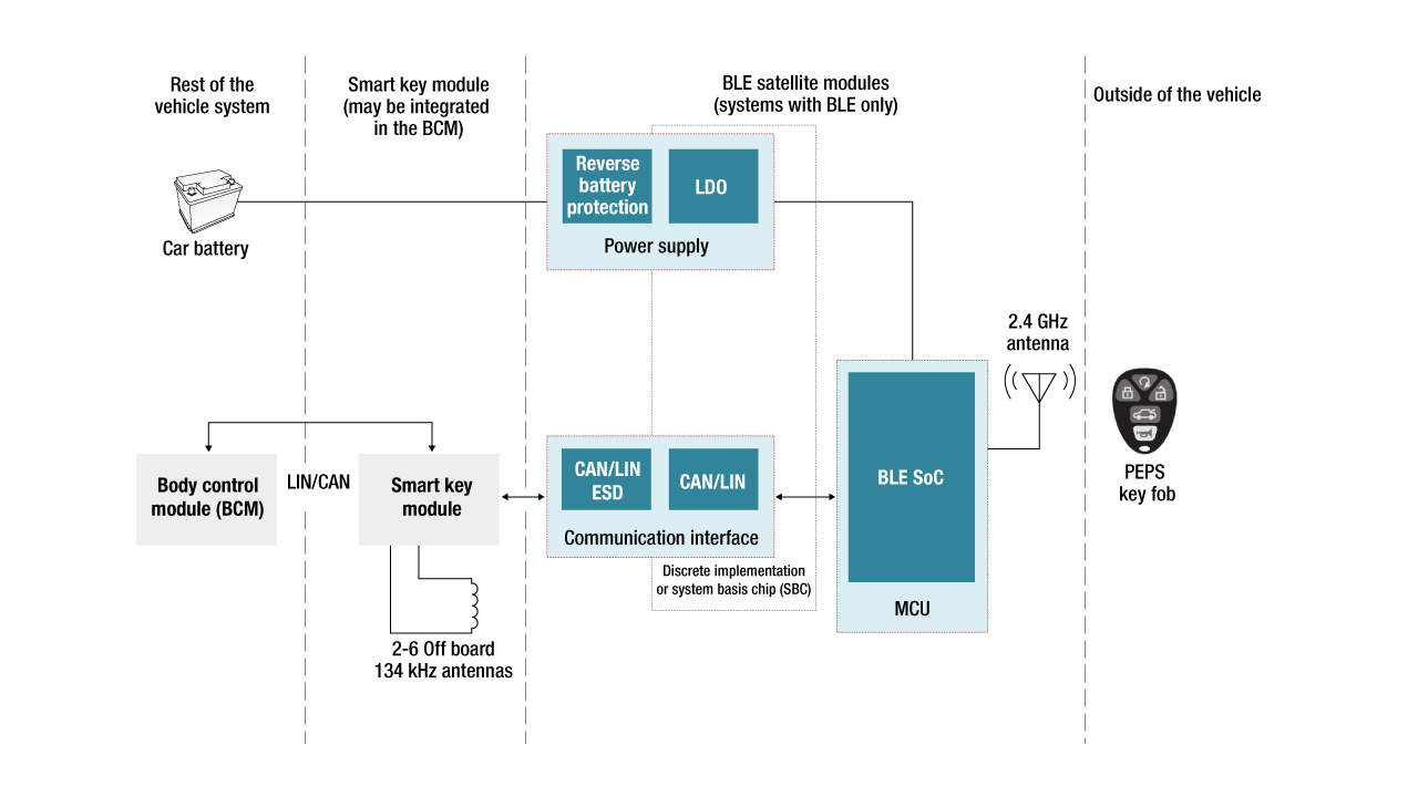
There is one central smart key module and nine satellite modules in such a typical architecture of Bluetooth Low Energy PEPS in a car.The nine satellite modules shown here are only an example; a real implementation could have more or fewer satellite modules. Figure 1 also shows that these modules communicate using a communication bus.
Inside the satellite node
So what is inside the satellite node? Figure 2 shows a typical block diagram of a Bluetooth Low Energy satellite module. The module has a Bluetooth Low Energy system-on-chip (SoC) such as TI’s SimpleLink™ CC2640R2F-Q1, a power supply, and a communication interface (typically a transceiver). Figure 2 also shows the rest of the modules involved in PEPS systems, including the smart key module and even the body control module.
Communication bus options
The two obvious communication bus architectures for car PEPS systems are Local Interconnect Network (LIN) and Controller Area Network (CAN); for the latter, either classical CAN or CAN Flexible Data Rate (CAN FD). Both LIN and CAN are standard communication protocols used widely in automotive applications. The maximum baud rate in a LIN communication system is 19.2 Kbps. Classical CAN is 1 Mbps and CAN FD can be up to 5 Mbps.
Both LIN and CAN use message frames as the basis for building the communication protocol; both can carry a maximum of 8 data bytes. A LIN message frame with 8 data bytes is 124 bits long, while the message frame in a standard CAN frame or CAN 2.0 frame (including the interframe space and assuming worst-case bit stuffing) can be 135 bits. Thus, a LIN message frame takes 6.46 ms to transmit, while a standard CAN message frame takes only 135 µs to transmit.
Choosing between LIN and CAN
As these calculations show, a LIN message frame takes longer than a CAN frame. So you might think the faster the better and choose the CAN bus. However, a CAN bus is a two-wire communication bus, whereas a LIN bus is a single-wire communication bus. This implies that a system based on a CAN bus is more expensive than a system that uses a LIN bus, which means that the CAN bus may not be the best choice.
How do you choose between the two protocols? One way is to analyze the total number of bytes that need transmitting. If the Bluetooth Low Energy chip implements computational algorithms in the satellite node, then the number of bytes that need transmitting will be lower, and thus, LIN communication would suffice. If, on the other hand, the Bluetooth Low Energy chip does not perform any computations but simply transmits all of the measured raw data, then many more bytes need transmitting, which necessitates CAN architecture.
One other consideration is power consumption. LIN bus-based nodes will typically consume less power than CAN bus in all modes of operation. The specific power consumption numbers are available in the respective transceiver data sheets.
Example implementations
TI’s automotive Bluetooth Low Energy car access satellite node reference design shows an implementation of a LIN-based satellite board. This reference design uses TI’s CC2640R2F-Q1 as the Bluetooth Low Energy SoC and TLIN1029-Q1 as the LIN bus transceiver.
Classical CAN or CAN FD bus architectures are an obvious choice when you have to exchange large amounts of data between the smart key module and the Bluetooth Low Energy satellite module. You can easily add CAN communication capability to the satellite nodes using TI’s new TCAN4550-Q1 system-basis chip (SBC), which integrates a CAN FD controller and transceiver. In addition to the integrated controller and transceiver, the SBC is self-supplied; that is, no additional power-supply devices are needed. The SBC provides a voltage source to power additional components in the printed circuit board and has a watchdog timer that can serve as the SoC monitor.
Figure 3 shows a possible implementation of the satellite node using the TCAN4550-Q1 that takes advantage of the features in this device.
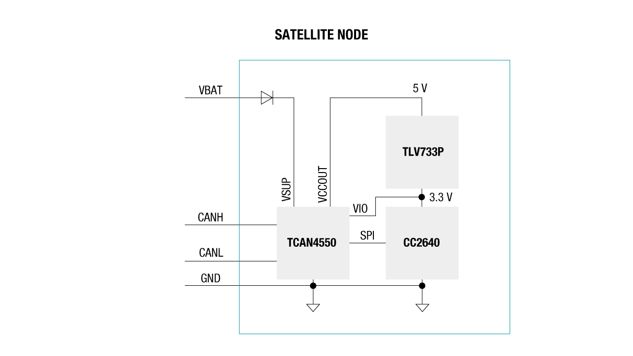
In Figure 3, the 5-V output from the TCAN4550-Q1 is used as the input to the TLV733P-Q1 low VIN linear regulator. This regulator generates the 3.3 V needed for the CC2640R2F-Q1 Bluetooth Low Energy SoC and eliminates the need for a wide VIN regulator to power the Bluetooth Low Energy SoC. Note that the 3.3-V regulator output is also used as VIO for the TCAN4550-Q1, thus eliminating the need for a voltage-level shifter between the Bluetooth Low Energy SoC and TCAN4550-Q1. The watchdog timer in the TCAN4550-Q1 can also monitor the Bluetooth Low Energy SoC software execution. This highly integrated SBC thus enables a cost-optimized solution for a Bluetooth Low Energy satellite node.
TI’s Car access Bluetooth® low energy + CAN satellite module reference design (TIDA-020032) demonstrates how CAN-FD communication capabilities can be implemented with our Bluetooth wireless MCUs for systems that require higher bandwidth in-vehicle network communications.
Conclusions
Design engineers are now implementing next-generation PEPS systems in cars using Bluetooth Low Energy technology. As designers address the challenge of optimal number of nodes required to meet PEPS requirements, the communication bus architecture plays an important role in the solution. Designers have the choice of choosing either LIN or CAN for communication. TI’s LIN transceivers and the newly introduced TCAN4550-Q1 SBC, along with Bluetooth Low Energy SoC and power management devices, provide not only the full portfolio of devices to choose from, but also the flexibility to develop the most optimal solution for car platforms.