Foreword
ISO (the International Organization for Standardization) is a worldwide federation of national standards bodies (ISO member bodies). The work of preparing International Standards is normally carried out through ISO technical committees. Each member body interested in a subject for which a technical committee has been established has the right to be represented on that committee. International organizations, governmental and non-governmental, in liaison with ISO, also take part in the work. ISO collaborates closely with the International Electrotechnical Commission (IEC) on all matters of electrotechnical standardization.
International Standards are drafted in accordance with the rules given in the ISO/IEC Directives, Part 2.
The main task of technical committees is to prepare International Standards. Draft International Standards adopted by the technical committees are circulated to the member bodies for voting. Publication as an International Standard requires approval by at least 75 % of the member bodies casting a vote.
Attention is drawn to the possibility that some of the elements of this document may be the subject of patent rights. ISO shall not be held responsible for identifying any or all such patent rights.
ISO 14229 was prepared by Technical Committee ISO/TC 22, Road vehicles, Subcommittee SC 3, Electrical and electronic equipment.
This second edition of ISO 14229 cancels and replaces the first edition (ISO 14229:1998), which has been technically revised.
Introduction
ISO 14229 has been established in order to define common requirements for diagnostic systems, whatever the serial data link is.
To achieve this, it is based on the Open Systems Interconnection (OSI) Basic Reference Model in accordance with ISO 7498-1 and ISO/IEC 10731, which structures communication systems into seven layers. When mapped on this model, the services used by a diagnostic tester (client) and an Electronic Control Unit (ECU, server) are broken into:
unified diagnostic services (layer 7); and
communication services (layers 1 to 6).
NOTE The diagnostic services in ISO 14229 are implemented in various applications, e.g. ISO 16844 (all parts), ISO 11992 (all parts), ISO 9141 (all parts), ISO 14230 (all parts), etc. Future modifications to this International Standard will provide long-term backward compatibility with the implementation standards as described above.
Table 1 — Example of diagnostic/programming specifications applicable to the OSI layers
Applicability
OSI layer
Enhanced diagnostics services (non-emissions-related)
Seven layers according to ISO/IEC 7498-1
and ISO/IEC 10731
Application (layer 7)
ISO 14229/ISO 15765-3/ISO 11992-4
ISO 14229/further standards
Presentation (layer 6)
—
—
Session (layer 5)
ISO 15765-3/ISO 11992-4
further standards
Transport (layer 4)
ISO 15765-2/ISO 11992-4
further standards
Network (layer 3)
ISO 15765-2/ISO 11992-4
further standards
Data link (layer 2)
ISO 11898/ISO 11992-1/SAE J1939-15
further standards
Physical (layer 1)
ISO 11898/ISO 11992-1/SAE J1939-15
further standards
Figure 1 shows an example of the possible future implementation of ISO 14229 onto various data links.
Figure 1 — Available International Standards and possible future implementations of ISO 14229
Road vehicles — Unified diagnostic services (UDS) — Specification and requirements
Scope
ISO 14229 specifies data link independent requirements of diagnostic services, which allow a diagnostic tester (client) to control diagnostic functions in an on-vehicle Electronic Control Unit (server) such as an electronic fuel injection, automatic gear box, anti-lock braking system, etc. connected on a serial data link embedded in a road vehicle. It specifies generic services which allow the diagnostic tester (client) to stop or to resume non- diagnostic message transmission on the data link. ISO 14229 does not apply to non-diagnostic message transmission or to use of the communication data link between two Electronic Control Units. It does not specify any implementation requirements.
The vehicle diagnostic architecture of ISO 14229 applies to:
a single tester (client) that may be temporarily or permanently connected to the on-vehicle diagnostic data link; and
several on-vehicle Electronic Control Units (servers) connected directly or indirectly.
Figure 2 — Vehicle diagnostic architecture
In Figure 2:
For vehicle 1, the servers are connected over an internal data link and indirectly connected to the diagnostic data link through a gateway. ISO 14229 applies to the diagnostic communications over the diagnostic data link; the diagnostic communications over the internal data link may conform to ISO 14229 or to another protocol.
For vehicle 2, the servers are directly connected to the diagnostic data link.
For vehicle 3, the servers are directly connected to the diagnostic data link through a gateway (same as vehicle 2) and vehicle 4 connects its server/gateway directly to the vehicle 3 server/gateway.
Normative references
The following referenced documents are indispensable for the application of this document. For dated references, only the edition cited applies. For undated references, the latest edition of the referenced document (including any amendments) applies.
ISO 7498-1, Information technology — Open Systems Interconnection — Basic Reference Model: The Basic Model
ISO/IEC 10731, Information technology — Open Systems Interconnection — Basic Reference Model — Conventions for the definition of OSI services
ISO 11898 (all parts), Road vehicles — Controller area network (CAN)
ISO 11992-1, Road vehicles — Interchange of digital information on electrical connections between towing and towed vehicles — Part 1: Physical and data-link layers
ISO 11992-4, Road vehicles — Interchange of digital information on electrical connections between towing and towed vehicles — Part 4: Diagnostics
ISO 14230 (all parts), Road vehicles — Diagnostic systems — Keyword Protocol 2000
ISO 15765-2, Road vehicles — Diagnostics on Controller Area Networks (CAN) — Part 2: Network layer services
ISO 15765-3, Road vehicles — Diagnostics on Controller Area Networks (CAN) — Part 3: Implementation of unified diagnostic services (UDS on CAN)
ISO/TR 15031-2, Road vehicles — Communication between vehicle and external equipment for emissions- related diagnostics — Part 2: Terms, definitions, abbreviations and acronyms
ISO 15031-5, Road vehicles — Communication between vehicle and external equipment for emissions-related diagnostics — Part 5: Emissions-related diagnostic services
ISO 15031-6, Road vehicles — Communication between vehicle and external equipment for emissions-related diagnostics — Part 6: Diagnostic trouble code definitions
ISO 15031-7, Road vehicles — Communication between vehicle and external equipment for emissions-related diagnostics — Part 7: Data link security
ISO 15764, Road vehicles — Extended data link security
Terms and definitions
For the purposes of this document, the following terms and definitions apply.
3.1
integer type
simple type with distinguished values which are the positive and the negative whole numbers
NOTE The range of integer type is not specified within this document.
3.2
diagnostic trouble code
numerical common identifier for a fault condition identified by the on-board diagnostic system
3.3
diagnostic service
information exchange initiated by a client in order to require diagnostic information from a server and/or to modify its behaviour for diagnostic purposes
3.4
client
function that is part of the tester and that makes use of the diagnostic services
NOTE A tester normally makes use of other functions such as database management, specific interpretation, human- machine interface.
3.5
server
function that is part of an electronic control unit and that provides the diagnostic services
NOTE ISO 14229 differentiates between the server (i.e. the function) and the electronic control unit so that this International Standard remains independent from the implementation.
3.6
tester
system that controls functions such as test, inspection, monitoring or diagnosis of an on-vehicle electronic control unit and which may be dedicated to a specific type of operator (e.g. a scan tool dedicated to garage mechanics or a test tool dedicated to assembly plant agents)
NOTE The tester is also referenced as the client.
3.7
diagnostic data
data that is located in the memory of an electronic control unit which may be inspected and/or possibly modified by the tester (diagnostic data includes analogue inputs and outputs, digital inputs and outputs, intermediate values and various status information)
EXAMPLES Examples of diagnostic data include vehicle speed, throttle angle, mirror position, system status, etc. Three types of values are defined for diagnostic data:
the current value: the value currently used by (or resulting from) the normal operation of the electronic control unit;
a stored value: an internal copy of the current value made at specific moments, e.g. when a malfunction occurs or periodically (this copy is made under the control of the electronic control unit);
a static value: e.g. VIN; the server is not obliged to keep internal copies of its data for diagnostic purposes, in which case the tester may only request the current value.
3.8
diagnostic session
current mode of the server, which affects the level of diagnostic functionality
NOTE Defining a repair shop or development testing session selects different server functionality (e.g. access to all memory locations may only be allowed in the development testing session).
3.9
diagnostic routine
routine that is embedded in an electronic control unit and that may be started by a server upon a request from the client
NOTE It could either run instead of a normal operating program or run concurrently to the normal operating program. In the first case, normal operation of the ECU is not possible. In the second case, multiple diagnostic routines may be enabled that run while all other parts of the electronic control unit are functioning normally.
3.10
record
one or more diagnostic data elements that are referred to together by a single means of identification
NOTE A snapshot including various input/output data and trouble codes is an example of a record.
3.11
security
as used in ISO 14229, security access method that satisfies the requirements for tamper protection as specified in ISO 15031-7
3.12
functional unit
set of functionally close or complementary diagnostic services
3.13
local server
server that is connected to the same local network as the client and is part of the same address space as the client
3.14
local client
client that is connected to the same local network as the server and is part of the same address space as the server
3.15
remote server
server that is not directly connected to the main diagnostic network
NOTE 1 A remote server is identified by means of a remote network address. Remote network addresses represent an own network address space that is independent from the addresses on the main network.
NOTE 2 A remote server is reached via a local server on the main network. Each local server on the main network can act as a gate to one independent set of remote servers. A pair of addresses will therefore always identify a remote server: a local address that identifies the gate to the remote network and a remote address identifying the remote server itself.
3.16
remote client
client that is not directly connected to the main diagnostic network
NOTE A remote client is identified by means of a remote network address. Remote network addresses represent an own address space that is independent from the addresses on the main network.
3.17
permanent DTC
stored in NVRAM and not erasable by any test equipment command or by disconnecting power to the on-board computer
Symbols and abbreviated terms
A_PCI Application layer Protocol Control Information A_PDU Application layer Protocol Data Unit
A_SDU Application layer Service Data Unit ECU Electronic Control Unit
NOTE An ECU contains at least one server. Systems considered as Electronic Control Units include anti-lock braking system (ABS), engine management system, etc.
NR_SI Negative Response Service Identifier OBD On-Board Diagnostic
OSI Open Systems Interconnection
RA Remote Address
SA Source Address
SI Service Identifier
TA Target Address TA_type Target Address type
Conventions
ISO 14229 is guided by the conventions discussed in the OSI Service Conventions (ISO 10731) as they apply to diagnostic services. These conventions specify the interactions between the service user and the service provider. Information is passed between the service user and the service provider by service primitives, which may convey parameters.
The distinction between service and protocol is summarized in Figure 3. ISO 14229 defines both, confirmed and unconfirmed services.
Confirmed services use the six (6) service primitives, request, req_confirm, indication, response, rsp_confirm and confirmation.
Unconfirmed services use only the request, req_confirm and indication service primitives.
For all services defined in ISO 14229, the request and indication service primitives always have the same format and parameters. Consequently, for all services the response and confirmation service primitives (except req_confirm and rsp_confirm) always have the same format and parameters. When the service primitives are defined in this International Standard, only the request and response service primitives are listed.
Figure 3 — The services and the protocol
Application layer services
General
Application layer services are usually referred to as diagnostic services. The application layer services are used in client-server-based systems to perform functions such as test, inspection, monitoring or diagnosis of on-board vehicle servers. The client, usually referred to as an External Test Equipment, uses the application layer services to request diagnostic functions to be performed in one or more servers. The server, usually a function that is part of an ECU, uses the application layer services to send response data, provided by the requested diagnostic service, back to the client. The client is usually an off-board tester but can, in some systems, also be an on-board tester. The usage of application layer services is independent from the client being an off-board or on-board tester. It is possible to have more than one client in the same vehicle system.
The service access point of the diagnostics application layer provides a number of services that all have the same general structure. For each service, six (6) service primitives are specified:
a service request primitive, used by the client function in the diagnostic tester application to pass data about a requested diagnostic service to the diagnostics application layer;
a service request-confirmation primitive, used by the client function in the diagnostic tester application to indicate that the data passed in the service request primitive is completely transferred to the server;
a service indication primitive, used by the diagnostics application layer to pass data to the server function of the ECU diagnostic application;
a service response primitive, used by the server function in the ECU diagnostic application to pass response data provided by the requested diagnostic service to the diagnostics application layer;
a service response-confirmation primitive, used by the server function in the ECU diagnostic application to indicate that the data passed in the service response primitive is completely transferred to the client;
a service confirmation primitive, used by the diagnostics application layer to pass data to the client function in the diagnostic tester application.
Figure 4 — Application layer service primitives — confirmed service
Figure 5 — Application layer service primitives — unconfirmed service
For a given service, the request primitive and the indication primitive always have the same service data unit. ISO 14229 will only list and specify the parameters of the service data unit belonging to each service request primitive. The user shall assume exactly the same parameters for each corresponding service indication primitive.
For a given service, the response primitive and the confirmation primitive always have the same service data unit. ISO 14229 only lists and specifies the parameters of the service data unit belonging to each service response primitive. The user shall assume exactly the same parameters for each corresponding service confirmation primitive.
For each service response primitive (and corresponding service confirmation primitive), two different service data units (two sets of parameters) will be specified. One set of parameters shall be used in a positive service response primitive if the requested diagnostic service can be successfully performed by the server function in the ECU diagnostic application. The other set of parameters (the negative response service data unit) shall be used if the requested diagnostic service fails or cannot be completed in time by the server function in the ECU diagnostic application.
For a given service, the request-confirmation primitive and the response-confirmation primitive always have the same service data unit. The purpose of these service primitives is to indicate the completion of an earlier request or response service primitive invocation. The service descriptions in ISO 14229 do not make use of those service primitives, but the data link specific implementation documents might use them to define e.g. service execution reference points (e.g. the ECUReset service would reset the ECU after the response has been completely transmitted to the client, which is indicated in the server by the service response-confirm primitive).
Format description of application layer services
Application layer services can have two different formats depending on how the vehicle diagnostic system is configured.
If the vehicle system is configured as a single (one logical) diagnostic network where all clients and servers are connected directly, then the default (also called normal or standard) format of application layer services shall be used. This format is compatible with the diagnostic system formats used on data links such as K- and L-lines. The default application layer services format is specified in 6.3.
The remote format of application layer services shall be used in vehicle systems implementing the concept of local servers and remote servers. The remote format has one additional address parameter called remote address. The remote format is used to access servers that are not directly connected to the main diagnostic network in the vehicle. The remote format for application layer services is specified in 6.4.
Format description of standard service primitives
General definition
All application layer services have the same general format. Service primitives are written in the form:
service_name.type (
parameter A, parameter B, parameter C
,parameter 1, ...
)
where:
“service_name” is the name of the diagnostic service (e.g. DiagnosticSessionControl);
“type” indicates the type of the service primitive (e.g. request);
“parameter A, ...” is the A_SDU as a list of values passed by the service primitive (addressing information);
“parameter A, parameter B, parameter C” are mandatory parameters that shall be included in all service calls;
“,parameter 1, ...” are parameters that depend on the specific service (e.g. parameter 1 can be the diagnosticSession for the DiagnosticSessionControl service). The brackets indicate that this part of the parameter list may be empty.
Service request and service indication primitives
For each application layer service, service request and service indication primitives are specified according to the following general format:
service_name.request (
SA,
TA,
TA_type
,parameter 1, ...
)
The request primitive is used by the client function in the diagnostic tester application to initiate the service and pass data about the requested diagnostic service to the application layer.
service_name.indication (
SA,
TA,
TA_type
,parameter 1, ...
)
The indication primitive is used by the application layer to indicate an internal event which is significant to the ECU diagnostic application and to pass data about the requested diagnostic service to the server function of the ECU diagnostic application.
The request and indication primitives of a specific application layer service always have the same parameters and parameter values. This means that the values of individual parameters shall not be changed by the communicating peer protocol entities of the application layer when the data is transmitted from the client to the server. The same values that are passed by the client function in the client application to the application layer in the service request call shall be received by the server function of the diagnostic application from the service indication of the peer application layer.
Service response and service confirm primitives
For each confirmed application layer service, service response and service confirm primitives are specified according to the following general format:
service_name.response (
SA,
TA,
TA_type, Result
,parameter 1, ...
)
The response primitive is used by the server function in the ECU diagnostic application, to initiate the service and pass response data provided by the requested diagnostic service to the application layer.
service_name.confirm (
SA,
TA,
TA_type, Result
,parameter 1, ...
)
The confirm primitive is used by the application layer to indicate an internal event which is significant to the client application and to pass results of an associated previous service request to the client function in the diagnostic tester application. It does not necessarily indicate any activity at the remote peer interface, e.g. if the requested service is not supported by the server or if the communication is broken.
The response and confirm primitives of a specific application layer service always have the same parameters and parameter values. This means that the values of individual parameters shall not be changed by the communicating peer protocol entities of the application layer when the data is transmitted from the server to the client. The same values that are passed by the server function of the ECU diagnostic application to the application layer in the service response call shall be received by the client function in the diagnostic tester application from the service confirmation of the peer application layer.
For each response and confirm primitive two different service data units (two sets of parameters) will be specified.
A positive response and positive confirm primitive shall be used with the first service data unit if the requested diagnostic service could be successfully performed by the server function in the ECU.
A negative response and confirm primitive shall be used with the second service data unit if the requested diagnostic service failed or could not be completed in time by the server function in the ECU.
Service request-confirm and service response-confirm primitives
For each application layer service, service request-confirm and service response-confirm primitives are specified according to the following general format:
service_name.req_confirm(
SA,
TA,
TA_type, Result
)
The request-confirm primitive is used by the application layer to indicate an internal event, which is significant to the client application, and pass results of an associated previous service request to the client function in the diagnostic tester application.
service_name.rsp_confirm(
SA,
TA,
TA_type, Result
)
The response-confirm primitive is used by the application layer to indicate an internal event, which is significant to the server application, and pass results of an associated previous service response to the server function in the ECU application.
Format description of remote service primitives
General definition
Diagnostic communication between a local client and a remote server can take place if the remote format of application layer services is used. All definitions made for the default format of application layer services shall be applicable also for the remote format of application layer services with the addition of one more addressing parameter.
Diagnostic communication can take place between a local client on the main network and one or more remote servers on a remote network. Communication can also take place between a remote client on a remote network and one or more local servers on the main network.
Diagnostic communication cannot take place between any combination of clients and servers on two different remote networks.
All remote format application layer services have the same general format. Service primitives are written in the form:
service_name.type (
parameter A, parameter B, parameter C, parameter D
,parameter 1, ...
)
where:
“service_name” is the name of the diagnostic service (e.g. DiagnosticSessionControl);
“type” indicates the type of the service primitive (e.g. request);
“parameter A, ...” is the A_SDU as a list of values passed by the service primitive (addressing information);
“parameter A, parameter B, parameter C” are mandatory parameters that shall be included in all service calls;
“parameter D” is an additional parameter that is only used in vehicles implementing the concept of remote servers (remote address);
“,parameter 1, ...” are parameters that depend on the specific service (e.g. parameter 1 can be the diagnosticSession for the DiagnosticSessionControl service). The brackets indicate that this part of the parameter list may be empty.
Remote service request and service indication primitives
For each remote format application layer service, service request and service indication primitives are specified according to the following general format:
service_name.request (
SA,
TA,
TA_type [,RA]
,parameter 1, ...
)
The request primitive is used by the local client function in the client application, to initiate the service and pass data about the requested diagnostic service to the application layer.
service_name.indication (
SA,
TA,
TA_type [,RA]
,parameter 1, ...
)
The indication primitive is used by the remote application layer to indicate an internal event which is significant to the ECU diagnostic application and to pass data about the requested diagnostic service to the remote server function of the ECU diagnostic application.
The request and indication primitive of a specific application layer service always have the same parameters and parameter values. This means that the values of individual parameters shall not be changed by the communicating peer protocol entities of the application layer when the data is transmitted from the client to the server. The same values that are passed by the client function in the diagnostic tester application to the application layer in the service request call shall be received by the server function of the ECU application from the service indication of the peer application layer.
NOTE For clarity, the text assumes communication between a local client and one or more remote server. The protocol also supports communication between a remote client and one or more local servers using the same remote format application layer services.
Remote service response and service confirm primitives
For each remote format application layer service, service response and service confirm primitives are specified according to the following general format:
service_name.response (
SA,
TA,
TA_type, [RA,]
Result
,parameter 1, ...
)
The response primitive is used by the remote server function in the ECU diagnostic application, to initiate the service and pass response data provided by the requested diagnostic service to the application layer.
service_name.confirm (
SA,
TA,
TA_type, [RA,]
Result
,parameter 1, ...
)
The confirm primitive is used by the local application layer to indicate an internal event which is significant to the client application and to pass results of an associated previous service request to the client function in the ECU application. It does not necessarily indicate any activity at the remote peer interface, e.g. if the requested service is not supported by the server or if the communication is broken.
The response and confirm primitive of a specific application layer service always has the same parameters and parameter values. This means that the values of individual parameters shall not be changed by the communicating peer protocol entities of the application layer when the data is transmitted from the server to the client. The same values that are passed by the server function of the ECU diagnostic application to the application layer in the service response call shall be received by the client function in the diagnostic tester application from the service confirmation of the peer application layer.
For each response and confirm primitive, two different service data units (two sets of parameters) will be specified.
A positive response and positive confirm primitive shall be used with the first service data unit if the requested diagnostic service could be successfully performed by the server function in the ECU.
A negative response and confirm primitive shall be used with the second service data unit if the requested diagnostic service failed or could not be completed in time by the server function in the ECU.
NOTE For clarity, the text assumes communication between a local client and one or more remote server. The protocol also supports communication between a remote client and one or more local servers using the same remote format application layer services.
Remote service request-confirm and service response-confirm primitives
For each application layer service, service request-confirm and service response-confirm primitives are specified according to the following general format:
service_name.req_confirm(
SA,
TA,
TA_type, [RA,]
Result
)
The request-confirm primitive is used by the client application layer to indicate an internal event which is significant to the client application and to pass results of an associated previous service request to the client function in the ECU application.
service_name.rsp_confirm(
SA,
TA, [RA,]
TA_type, Result,
)
The response-confirm primitive is used by the server application layer to indicate an internal event which is significant to the server application and to pass results of an associated previous service response to the server function in the ECU application.
Service data unit specification
Mandatory parameters
General definition
The application layer services contain three (3) mandatory parameters. The following parameter definitions are applicable to all application layer services specified in this International Standard (standard and remote format).
Source address (SA) Type: 1 byte unsigned integer value Range: 00-FF hex
Description:
The parameter SA shall be used to encode client and server identifiers, and it shall be used to represent the physical location of a client or server.
For service requests (and service indications), SA represents the client identifier for the client function that has requested the diagnostic service. The client shall always be located in one diagnostic tester only. There shall be a strict, one-to-one relation between client identifiers and source addresses. Each client identifier shall be encoded with one SA value. If more than one client is implemented in the same diagnostic tester, then each client shall have its own client identifier and corresponding SA value.
For service responses (and service confirmations), SA represents the physical location of the server that has performed the requested diagnostic service. A server may be implemented in one ECU only or be distributed and implemented in several ECUs. If a server is implemented in one ECU only, then it shall be encoded with one SA value only. If a server is distributed and implemented in several ECUs, then the server identifier shall be encoded with one SA value for each physical location of the server.
If a remote client or server is the original source for a message, then SA represents the local server that is the gate from the remote network to the main network.
NOTE The SA value in a response message will be the same as the TA value in the corresponding request message if physical addressing was used for the request message.
Target address (TA)
Type: 1 byte unsigned integer value Range: 00-FF hex
Description:
The parameter TA shall be used to encode client and server identifiers.
Two different addressing methods, called physical addressing and functional addressing, are specified for diagnostics. Therefore, two independent sets of target addresses can be defined for a vehicle system (one for each addressing method).
Physical addressing shall always be a dedicated message to a server implemented in one ECU. When physical addressing is used, the communication is a point-to-point communication between the client and the server.
Functional addressing is used by the client if it does not know the physical address of the server that will respond to a service request or if the server is implemented as a distributed server in several ECUs. When functional addressing is used, the communication is a broadcast communication from the client to a server implemented in one or more ECUs.
For service requests (and service indications), TA represents the server identifier for the server that will perform the requested diagnostic service. If a remote server is being addressed, then TA represents the local server that is the gate from the main network to the remote network.
For service responses (and service confirmations), TA represents the client identifier for the client that originally requested the diagnostic service and will receive the requested data. Service responses (and service confirmations) shall always use physical addressing. If a remote client is being addressed, then TA represents the local server that is the gate from the main network to the remote network.
NOTE The TA value of a response message will always be the same as the SA value of the corresponding request message.
TA_Type, Target Address type
Type: enumeration Range: physical, functional
Description:
The parameter TA_type is an extension to the TA parameter. It is used to represent the addressing method chosen for a message transmission.
Result Type: enumeration Range: positive, negative Description:
The parameter “Result” is used by the response and confirm primitives to indicate if a message is a positive response/positive confirm message or a negative response/negative confirm message. The service-specific parameters in the message are different depending on the value of the Result parameter.
Vehicle system requirements
The vehicle manufacturer shall ensure that each server in the system has a unique server identifier. The vehicle manufacturer shall also ensure that each client in the system has a unique client identifier.
All client and server identifiers for the main diagnostic network in a vehicle system shall be encoded into the same range of source addresses. This means that a client and a server shall not be represented by the same SA value in a given vehicle system.
The physical target address for a server shall always be the same as the source address for the server.
Remote server identifiers can be assigned independently from client and server identifiers on the main network.
In general only the server(s) addressed shall respond to the client request message.
Optional parameters
Remote address (RA) Type: 1 byte unsigned integer value Range: 00-FF hex
Description:
RA is used to extend the available address range to encode client and server identifiers. RA shall only be used in vehicles that implement the concept of local servers and remote servers. Remote addresses represent their own address range and are independent from the addresses on the main network.
The parameter RA shall be used to encode remote client and server identifiers. RA can represent either a remote target address or a remote source address, depending on the direction of the message carrying the RA.
For service requests (and service indications) sent by a client on the main network, RA represents the remote server identifier (remote target address) for the server that will perform the requested diagnostic service.
RA can be used both as a physical and a functional address. For each value of RA, the system builder shall specify if that value represents a physical or functional address.
NOTE There is no special parameter that represents physical or functional remote addresses in the way TA_type specifies the addressing method for TA. Physical and functional remote addresses share the same 1 byte range of values and the meaning of each value shall be defined by the system builder.
For service responses (and service confirmations) sent by a remote server, RA represents the physical location (remote source address) of the remote server that has performed the requested diagnostic service.
A remote server may be implemented in one ECU only or be distributed and implemented in several ECUs. If a remote server is implemented in one ECU only, then it shall be encoded with one RA value only. If a remote server is distributed and implemented in several ECUs, then the remote server identifier shall be encoded with one RA value for each physical location of the remote server.
For service requests (and service indications) sent by a remote client, RA represents the remote server identifier (remote source address) for the client function that has requested the diagnostic service.
For service responses (and service confirmations) sent by a local server, RA represents the remote client identifier (remote target address) for the client that originally requested the diagnostic service and shall receive the requested data.
Remote server example with remote network
In some systems, the remote server is connected to a remote network separated from the main diagnostic network by a gateway. The following is an example showing how the parameters SA, TA and RA shall be used for proper communication between a local client on the main network and a remote server via a gateway. In the example, it is assumed that the same type of addressing is used on the remote network as on the main network.
The external test equipment is connected to the main network and has client identifier 241 (F1 hex). The gateway is connected to both the main network and the remote network. On the main network the gateway has client identifier 200 (C8 hex). On the remote network, the gateway has client identifier 10 (0A hex). The remote server is connected to the remote network and has client identifier 62 (3E hex). The configuration is described in Figure 6.
Figure 6 — Remote server system example 1
The external test equipment sends a remote diagnostic request message with
⎯ SA = 241 (F1 hex),
TA = 200 (C8 hex), and
⎯ RA = 62 (3E hex).
The gateway receives the message and sends it out on the remote network with
⎯ SA = 10 (0A hex),
TA = 62 (3E hex), and
⎯ RA = 241 (F1 hex).
The remote server receives the message.
The remote server sends back a remote diagnostic response message with
⎯ SA = 62 (3E hex),
TA = 10 (0A hex), and
⎯ RA = 241 (F1 hex).
The gateway receives the message and sends it out on the main network with
⎯ SA = 200 (C8 hex),
TA = 241 (F1 hex), and
⎯ RA = 62 (3E hex).
The external test equipment receives the message.
Remote server example without remote network
In some systems, the remote server is a functional part of a server belonging to the main network. The server has been given a remote server identifier in order to extend the available address range to encode client and server identifiers. In such systems the remote server is logically separated from the main network even if the ECU, of which the remote server is a part, is connected to the main diagnostic network. To get a working system, the server must also have a gateway function that is part of the main diagnostic network and can serve as a gate to the remote server. The following is an example showing how the parameters SA, TA and RA are used for proper communication between a local client on the main network and a remote server via a gateway.
The external test equipment is connected to the main network and has client identifier 241 (F1 hex). The gateway is connected to the same main network. The gateway has client identifier 200 (C8 hex). The remote server has client identifier 62 (3E hex). The configuration is described in Figure 7.
Figure 7 — Remote server system example 2
The external test equipment sends a remote diagnostic request message with
⎯ SA = 241 (F1 hex),
TA = 200 (C8 hex), and
⎯ RA = 62 (3E hex).
The gateway receives the message and passes it over to the remote server function. The remote server receives the message.
The remote server sends back a remote diagnostic response message by passing it to the gateway function. The gateway receives the message and sends it out on the main network with
⎯ SA = 200 (C8 hex),
TA = 241 (F1 hex), and
⎯ RA = 62 (3E hex).
The external test equipment receives the message.
Remote client example with remote network
In some systems, the client is connected to a remote network separated from the main diagnostic network by a gateway. The following is an example showing how the parameters SA, TA and RA are used for proper communication between a remote client on a remote network and a local server on the main network via a gateway. In the example, it is assumed that the same type of addressing is used on the remote network as on the main network.
The external test equipment is connected to the remote network and has client identifier 242 (F2 hex). The gateway is connected to both the main network and the remote network. On the main network, the gateway has client identifier 200 (C8 hex). On the remote network, the gateway has client identifier 10 (0A hex). The local server is connected to the main network and has client identifier 18 (12 hex). The configuration is described in Figure 8.
Figure 8 — Remote client example
The external test equipment sends a remote diagnostic request message with
⎯ SA = 242 (F1 hex),
TA = 10 (0A hex), and
⎯ RA = 18 (12 hex).
The gateway receives the message and sends it out on the main network with
SA = 200 dec,
TA = 18 dec, and
RA = 242 dec.
The local server receives the message.
The local server sends back a remote diagnostic response message with
⎯ SA = 18 (12 hex),
TA = 200 (C8 hex), and
⎯ RA = 242 (F1 hex).
The gateway receives the message and sends it out on the remote network with
⎯ SA = 10 (0A hex),
TA = 242 (F1 hex), and
⎯ RA = 18 (12 hex).
The external test equipment receives the message.
Application layer protocol
General definition
The application layer protocol shall always be a confirmed message transmission, meaning that for each service request sent from the client, there shall be one or more corresponding responses sent from the server.
The only exception to this rule shall be a few cases when e.g. functional addressing is used or the request/indication specifies that no response/confirmation shall be generated. In order not to burden the system with many unnecessary messages, there are a few cases when negative response messages shall not be sent even if the server failed to complete the requested diagnostic service.
The application layer protocol shall be handled in parallel with the session layer protocol. This means that, even if the client is waiting for a response to a previous request, it shall maintain proper session layer timing (e.g. sending a TesterPresent request if that is needed to keep a diagnostic session going in other servers; the implementation depends on the data link layer used).
Protocol data unit specification
The A_PDU is directly constructed from the A_SDU and the layer-specific control information A_PCI (Application layer Protocol Control Information). The A_PDU shall have the following general format:
A_PDU (
SA,
TA,
TA_type, [RA,]
A_Data = A_PCI + parameter 1, ...
)
where:
“SA, TA, TA_type, RA” are the same parameters as used in the A_SDU;
“A_Data” is a string of byte data defined for each individual application layer service. The A_Data string shall start with the A_PCI followed by all service-specific parameters from the A_SDU as specified for each service. The brackets indicate that this part of the parameter list may be empty.
Application protocol control information
The A_PCI shall have two alternative formats depending on which type of service primitive that has been called and the value of the Result parameter. For all service requests and for service responses/service confirmations with Result = positive, the following definition shall apply:
A_PCI (
SI
)
where “SI” is the parameter service identifier.
19
For service responses/service confirmations with Result = negative, the following definition shall apply:
A_PCI (
NR_SI, SI
)
where:
“NR_SI” is the special parameter identifying negative service responses/confirmations;
“SI” is the parameter service identifier.
NOTE For the transmission of periodic messages utilizing response message type #2 as defined in the service ReadDataByPeriodicIdentifier (2A hex, see 10.5) no A_PCI is present in the application layer protocol data unit (A_PDU).
Service identifier (SI)
Type: 1 byte unsigned integer value
Range: 00-FF hex according to definitions in Table 2
Table 2 — Service identifier (SI) values
Service identifier (hex value)
Service type (bit 6)
Where defined
00 – 0F
OBD service requests
ISO 15031-5
10 – 3E
ISO 14229 service requests
ISO 14229
3F
Not applicable
Reserved by document
40 – 4F
OBD service responses
ISO 15031-5
50 – 7E
ISO 14229 positive service responses
ISO 14229
7F
Negative response service identifier
ISO 14229
80
Not applicable
Reserved by ISO 14229
81 – 82
Not applicable
Reserved by ISO 14230
83 – 88
ISO 14229 service requests
ISO 14229
89 – 9F
Service requests
Reserved for future expansion as needed
A0 – B9
Service requests
Defined by vehicle manufacturer
BA – BE
Service requests
Defined by system supplier
BF
Not applicable
Reserved by document
C0
Not applicable
Reserved by ISO 14229
C1 – C2
Not applicable
Reserved by ISO 14230
C3 – C8
ISO 14229 positive service responses
ISO 14229
C9 – DF
Positive service responses
Reserved for future expansion as needed
E0 – F9
Positive service responses
Defined by vehicle manufacturer
FA – FE
Positive service responses
Defined by system supplier
FF
Not applicable
Reserved by document
NOTE There is a one-to-one correspondence between service identifiers for request messages and service identifiers for positive response messages, with bit 6 of the SI hex value indicating the service type. All request messages have SI bit 6 = 0. All positive response messages have SI bit 6 = 1, except response message type #2 of the ReadDataByPeriodicIdentifier (2A hex, see section 10.5) service.
Description:
The SI shall be used to encode the specific service that has been called in the service primitive. Each request service shall be assigned a unique SI value. Each positive response service shall be assigned a corresponding unique SI value.
The service identifier is used to represent the service in the A_Data data string that is passed from the application layer to lower layers (and returned from lower layers).
Negative response service identifier (NR_SI)
Type: 1 byte unsigned integer value Fixed value: 7F hex
Description:
The parameter NR_SI is a special parameter identifying negative service responses/confirmations. It shall be part of the A_PCI for negative response/confirm messages.
NOTE The NR_SI value is coordinated with the SI values. The NR_SI value is not used as an SI value in order to make A_Data coding and decoding easier.
Negative response/confirmation service primitive
Each diagnostic service has a negative response/negative confirmation message specified with message A_Data bytes according to Table 3. The first A_Data byte (A_PCI.NR_SI) is always the specific negative response service identifier. The second A_Data byte (A_PCI.SI) shall be a copy of the service identifier value from the service request/indication message to which the negative response message corresponds.
Table 3 — Negative response A_PDU
A_PDU parameter
Parameter name
Cvt
Hex value
Mnemonic
SA
Source Address
Ma
xx
SA
TA
Target Address
M
xx
TA
TA_type
Target Address type
M
xx
TA_type
RA
Remote Address (optional)
Cb
xx
RA
A_Data.A_PCI.NR_SI
Negative Response Service Id
M
7F
SIDNR
A_Data.A_PCI.SI
Request Service Id
M
xx
SIDRQ
A_Data.Parameter 1
responseCode
M
xx
NRC_
M (Mandatory): In case the negative response A_PDU is issued then those A_PDU parameters shall be present.
C (Conditional): The RA (Remote Address) PDU parameter is only present in case of remote addressing.
NOTE A_Data represents the message data bytes of the negative response message.
The parameter responseCode is used in the negative response message to indicate why the diagnostic service failed or could not be completed in time. Values are defined in A.1.
Server response implementation rules
General definitions
The following subclauses specify the behaviour of the server when executing a service. The server and the client shall follow these implementation rules.
Legend for subclauses 7.5.2, 7.5.3 and 7.5.4
Abbreviation Description
suppressPosRspMsgIndicationBit TRUE = server shall NOT send a positive response message
FALSE = server shall send a positive or negative response message
PosRsp Abbreviation for positive response message
NegRsp Abbreviation for negative response message
NoRsp Abbreviation for NOT sending a positive or negative response message
NRC Abbreviation for negative response code
ALL All of the requested data parameters (service without sub-function parameter) of the client request message are supported by the server
at least 1 At least 1 data parameter (service without sub-function parameter) of the client request message must be supported by the server
NONE None of the requested data parameters (service without sub-function parameter) of the client request message is supported by the server
The server shall support its list of diagnostic services regardless of addressing mode (physical, functional addressing type).
IMPORTANT — As required by the tables in the following subclauses, negative response messages with negative response codes of SNS (serviceNotSupported), SFNS (subFunctionNotSupported) and ROOR (requestOutOfRange) shall never be transmitted when functional addressing was used for the request message.
Request message with sub-function parameter and server response behaviour
Physically addressed client request message
The server response behaviour specified in this subclause is referenced in the service description of each service, which supports a sub-function parameter in the physically addressed request message received from the client.
Table 4 shows possible communication schemes with physical addressing.
Table 4 — Physically addressed request message with sub-function parameter and server response behaviour
Server case #
Client request message
Server capability
Server response
Comments on server response
Addressin g
scheme
subFunction (suppress- PosRspMsg- Indication- Bit)
Service ID supported
Sub- function supported
Data parameter supported (only if applicable)
Message
Negative: NRC/
section
1
physical
FALSE
(bit = 0)
YES
YES
At least 1
PosRsp
—
Server sends positive response
2
—
NegRsp
NRC=xx
Server sends negative response because error occurred reading the data parameters of the request message
3
NO
—
—
NRC=SNS
Negative response with NRC 11 hex
4
YES
NO
—
NRC=SFNS
Negative response with NRC 12 hex
5
TRUE
(bit = 1)
YES
YES
At least 1
NoRsp
—
Server does NOT send a response
6
—
NegRsp
NRC=xx
Server sends negative response because error occurred reading the data parameters of the request message
7
NO
—
—
NRC=SNS
Negative response with NRC 11 hex
8
YES
NO
—
NRC=SFNS
Negative response with NRC 12 hex
The following is a description of server response cases on physically addressed client request messages with subFunction.
Server sends a positive response message because the service identifier and sub-function parameter is supported by the client’s request with indication for a response message.
Server sends a negative response message (e.g. IMLOIF: incorrectMessageLengthOrIncorrectFormat) because the service identifier and sub-function parameter of the client's request is supported but some other error appeared (e.g. wrong PDU length according to service identifier and sub-function parameter in the request message) during processing of the sub-function.
Server sends a negative response message with the negative response code SNS (service not supported) because the service identifier of the client’s request is not supported with indication for a response message.
Server sends a negative response message with the negative response code SFNS (sub-function not supported) because the service identifier is supported and the sub-function parameter of the client's request is not supported with indication for a response message.
Server sends no response message because the service identifier and sub-function parameter is supported by the client’s request with indication for no response message. If a negative response code RCRRP (requestCorrectlyReceivedResponsePending) is used, a final response shall be given independent of the suppressPosRspMsgIndicationBit value.
Same effect as in 2) (e.g. a negative response message is sent) because the suppressPosRspMsgIndicationBit is ignored for any negative response that needs to be sent upon receipt of a physically addressed request message.
Same effect as in 3) (e.g. the negative response message is sent) because the suppressPosRspMsgIndicationBit is ignored for any negative response that needs to be sent upon receipt of a physically addressed request message.
Same effect as in 4) (e.g. the negative response message is sent) because the suppressPosRspMsgIndicationBit is ignored for any negative response that needs to be sent upon receipt of a physically addressed request message.
Functionally addressed client request message
The server response behaviour specified in this subclause is referenced in the service description of each service which supports a sub-function parameter in the functionally addressed request message received from the client.
Table 5 shows possible communication schemes with functional addressing.
Table 5 — Functionally addressed request message with sub-function parameter and server response behaviour
Server case #
Client request message
Server capability
Server response
Comments on server response
Addressing scheme
subFunction (suppress- PosRspMsg- Indication- Bit)
Service ID supported
Sub- function supported
Data parameter supported (only if applicable)
Message
Negative: NRC/
section
1
functional
FALSE
(bit = 0)
YES
YES
At least 1
PosRsp
—
Server sends positive response
2
At least 1
NegRsp
NRC=xx
Server sends negative response because error occurred reading the data parameters of the request message
3
None
NoRsp
—
Server does NOT send a response
4
NO
—
—
—
Server does NOT send a response
5
YES
NO
—
—
Server does NOT send a response
6
TRUE
(bit = 1)
YES
YES
At least 1
NoRsp
—
Server does NOT send a response
7
At least 1
NegRsp
NRC=xx
Server sends negative response because error occurred reading the data parameters of the request message
8
None
NoRsp
—
Server does NOT send a response
9
NO
—
—
—
Server does NOT send a response
10
YES
NO
—
—
Server does NOT send a response
Description of server response cases on functionally addressed client request messages with subFunction:
Server sends a positive response message because the service identifier and sub-function parameter is supported by the client's request with indication for a response message.
Server sends a negative response message (e.g. IMLOIF: incorrectMessageLengthOrIncorrectFormat) because the service identifier and sub-function parameter is supported by the client's request, but some other error appeared (e.g. wrong PDU length according to service identifier and sub-function parameter in the request message) during processing of the sub-function.
Server sends no response message because the negative response code ROOR (requestOutOfRange, which is identified by the server because the service identifier and sub-function parameter are supported but a required data parameter is not supported by the client's request) is always suppressed in case of a functionally addressed request message. The suppressPosRspMsgIndicationBit does not matter in such cases.
Server sends no response message because the negative response code SNS (serviceNotSupported, which is identified by the server because the service identifier is not supported by the client's request) is always suppressed in case of a functionally addressed request message. The suppressPosRspMsgIndicationBit does not matter in such cases.
Server sends no response message because the negative response code SFNS (subFunctionNotSupported, which is identified by the server because the service identifier is supported and the sub-function parameter is not supported by the client's request) is always suppressed in case of a functionally addressed request. The suppressPosRspMsgIndicationBit does not matter in such cases.
Server sends no response message because the service identifier and sub-function parameter is supported by the client's request with indication for no response message.
NOTE If a negative response code RCRRP (requestCorrectlyReceivedResponsePending) is used, a final response shall be given independent of the suppressPosRspMsgIndicationBit value.
Same effect as in 2) (e.g. a negative response message is sent) because the suppressPosRspMsgIndicationBit is ignored for any negative response. This is also true if the request message is functionally addressed.
Same effect as in 3) (e.g. no response message is sent) because the negative response code ROOR (requestOutOfRange, which is identified by the server because the service identifier and sub-function parameter are supported but a required data parameter is not supported by the client's request) is always suppressed in case of a functionally addressed request message. The suppressPosRspMsgIndicationBit does not matter in such a case.
Same effect as in 4) (e.g. no response message is sent) because the negative response code SNS (serviceNotSupported, which is identified by the server because the service identifier is not supported by the client's request) is always suppressed in case of a functionally addressed request message. The suppressPosRspMsgIndicationBit does not matter in such a case.
Same effect as in 5) (e.g. no response message is sent) because the negative response code SFNS (subFunctionNotSupported, which is identified by the server because the service identifier is supported and the sub-function parameter is not supported by the client's request) is always suppressed in case of a functionally addressed request message. The suppressPosRspMsgIndicationBit does not matter in such a case.
Request message without sub-function parameter and server response behaviour
Physically addressed client request message
The server response behaviour specified in this subclause is referenced in the service description of each service which does not support a sub-function parameter but a data parameter in the physically addressed request message received from the client.
Table 6 shows possible communication schemes with physical addressing.
Table 6 — Physically addressed request message without sub-function parameter and server response behaviour
Server case #
Client request message
Server capability
Server response
Comments on server response
Addressing scheme
Service ID supported
Parameter supported
Message
Negative: NRC/section
1
physical
YES
ALL
PosRsp
—
Server sends positive response
2
At least 1
—
Server sends positive response
3
At least 1, more than 1, or ALL
NegRsp
NRC=xx
Server sends negative response because error occurred reading data parameters of request message
4
NONE
NRC=ROOR
Negative response with NRC 31 hex
5
NO
—
NRC=SNS
Negative response with NRC 11 hex
The following is a description of server response cases on physically addressed client request messages without sub-function (data parameter follows service identifier).
Server sends a positive response message because the service identifier and all data parameters are supported by the client's request message.
Server sends a positive response message because the service identifier and a single data parameter is supported by the client's request message.
Server sends a negative response message (e.g. IMLOIF: incorrectMessageLengthOrIncorrectFormat) because the service identifier is supported and at least one, more than one or all data parameters are supported by the client's request message, but some other error occurred (e.g. wrong length of the request message) during processing of the service.
Server sends a negative response message with the negative response code ROOR (requestOutOfRange) because the service identifier is supported but none of the requested data parameters are supported by the client's request message.
Server sends a negative response message with the negative response code SNS (serviceNotSupported) because the service identifier is not supported by the client's request message.
Functionally addressed client request message
The server response behaviour specified in this subclause is referenced in the service description of each service which does not support a sub-function parameter but a data parameter in the functionally addressed request message received from the client.
Table 7 shows possible communication schemes with functional addressing.
Table 7 — Functionally addressed request message without sub-function parameter and server response behaviour
Server case #
Client request message
Server capability
Server response
Comments on server response
Addressing scheme
Service ID supported
Parameter supported
Message
Negative: NRC/section
1
functional
YES
YES
PosRsp
—
Server sends positive response
2
at least 1
—
Server sends positive response
3
At least 1,
more than 1, or ALL
NegRsp
NRC=xx
Server sends negative response because error occurred reading data parameters of request message
4
NONE
NoRsp
—
Server does NOT send a response
5
NO
—
—
Server does NOT send a response
The following is a description of server response cases on functionally addressed client request messages without sub-function (data parameter follows service identifier).
Server sends a positive response message because the service identifier and single data parameter is supported by the client's request message.
Server sends a positive response message because the service identifier and at least one data parameter is supported by the client's request message.
Server sends a negative response message (e.g. IMLOIF: incorrectMessageLengthOrIncorrectFormat) because the service identifier is supported and at least one, more than one or all data parameters are supported by the client's request message, but some other error occurred (e.g. wrong length of the request message) during processing of the service.
Server sends no response message because the negative response code ROOR (request out of range, which would occur because the service identifier is supported, but none of the requested data parameters is supported by the client's request) is always suppressed in case of a functionally addressed request.
Server sends no response message because the negative response code SNS (serviceNotSupported, which is identified by the server because the service identifier is not supported by the client's request) is always suppressed in case of a functionally addressed request.
Pseudo code example of server response behaviour
The following is a server pseudo code example to describe the logical steps a server shall perform when receiving a request from the client.
SWITCH (A_PDU.A_Data.A_PCI.SI)
{
CASE Service_with_subFunction: /* test if service with subFunction is supported */
SWITCH (A_PDU.A_Data.A_Data.Parameter1 & 0x7F) /* get subFunction parameter value without bit 7 */
{
CASE subFunction_00: /* test if subFunction parameter value is supported */
IF (message_length == expected_subFunction_message_length) THEN
: /* prepare response message */
responseCode = positiveResponse; /* positive response message; set internal NRC = 0x00 */
ELSE
responseCode = IMLOIF; /* NRC 0x13: incorrectMessageLengthOrInvalidFormat */
ENDIF BREAK;
CASE subFunction_01: /* test if subFunction parameter value is supported */
: /* prepare response message */
responseCode = positiveResponse; /* positive response message; set internal NRC = 0x00 */
:
:
:
CASE subFunction_127: /* test if subFunction parameter value is supported */
: /* prepare response message */
responseCode = positiveResponse; /* positive response message; set internal NRC = 0x00 */
BREAK; DEFAULT:
responseCode = SFNS; /* NRC 0x12: subFunctionNotSupported */
}
suppressPosRspMsgIndicationBit = (A_PDU.A_Data.Parameter1 & 0x80); /* results in either 0x00 or 0x80 */
IF ( (suppressPosRspMsgIndicationBit) && (responseCode == positiveResponse) ) THEN
/* test if positive response is required and if responseCode is positive 0x00 */
suppressResponse = TRUE; /* flag to NOT send a positive response message */
ELSE
suppressResponse = FALSE; /* flag to send the response message */
ENDIF BREAK;
CASE Service_without_subFunction: /* test if service without subFunction is supported */ suppressResponse = FALSE; /* flag to send the response message */
IF (message_length == expected_message_length) THEN
IF (A_PDU.A_Data.Parameter1 == supported) THEN /* test if data parameter following the SID is supported*/
: /* read data and prepare response message */
responseCode = positiveResponse; /* positive response message; set internal NRC = 0x00 */
ELSE
responseCode = ROOR; /* NRC 0x31: requestOutOfRange */
ENDIF ELSE
responseCode = IMLOIF; /* NRC 0x13: incorrectMessageLengthOrInvalidFormat */
ENDIF BREAK;
DEFAULT:
responseCode = SNS; /* NRC 0x11: serviceNotSupported */
}
IF (A_PDU.TA_type == functional && ((responseCode == SNS) ¦¦ (responseCode == SFNS) ¦¦ (responseCode == ROOR))) THEN
/* suppress negative response message */
ELSE
IF (suppressResponse == TRUE) THEN
/* suppress positive response message */
ELSE
/* send negative or positive response */
ENDIF ENDIF
When functional addressing is used for the request message, the negative response message with the negative response code (NRC) 78 hex, requestCorrectlyReceivedResponsePending (RCRRP), shall not be implemented if a negative response message with NRC=SNS (serviceNotSupported), NRC=SFNS (subFunctionNotSupported) or NRC=ROOR (requestOutOfRange) is the result of the PDU analysis of the received request message.
Multiple concurrent request messages with physical and functional addressing
A common server implementation has only one diagnostic protocol instance available in the server which can only handle one request at a time. The rule is that any received message (regardless of whether the addressing mode is physical or functional) occupies this resource until the request message is processed (with final response sent or application call without response).
There are only two (2) exceptions which have to be treated separately.
The keep-alive logic is used by a client to keep a previously enabled session active in one or multiple servers. Keep-Alive-Logic is defined as the functionally addressed valid TesterPresent message with SPRMIB=true and has to be processed by a bypass logic. It is up to the server to make sure that this specific message can not “block” the server’s application layer and that an immediately following addressed message can be processed.
If a server supports one or more legislated diagnostic requests and one of these requests is received while a non-legislated service (e.g. enhanced diagnostics) is active, then the active service shall be aborted, the default session shall be started and the legislated diagnostic service shall be processed. This requirement does not apply if the programming session is active.
Size of dataIdentifier (DID)
The dataIdentifier (DID) parameter has a size of two (2) bytes in all services throughout ISO 14229.
An implementation standard based on ISO 14229 shall specify the size of the dataIdentifier (DID) parameter if it does not match this International Standard.
Service description conventions
Service description
This clause defines how each diagnostic service is described in ISO 14229. It defines the general service description format of each diagnostic service.
This clause gives a brief outline of the functionality of the service. Each diagnostic service specification starts with a description of the actions performed by the client and the server(s) which are specific to each service. The description of each service includes a table which lists the parameters of its primitives: request/indication, response/confirmation for a positive or negative result. All have the same structure.
For a given request/indication and response/confirmation A_PDU definition, the presence of each parameter is described by one of the following convention (Cvt) values given in Table 8.
Table 8 — A_PDU parameter conventions
Type
Name
Description
M
Mandatory
The parameter shall be present in the A_PDU.
C
Conditional
The parameter can be present in the A_PDU, based on certain criteria (e.g. sub- function/parameters within the A_PDU).
S
Selection
Indicates that the parameter is mandatory (unless otherwise specified) and is a selection from a parameter list.
U
User option
The parameter may or may not be present, depending on dynamic usage by the user.
NOTE The “ Request Service Id” marked as “M” (Mandatory) shall not imply that this service must be supported by the server. The “M” only indicates the mandatory presence of this parameter in the request A_PDU if the server supports the service.
Request message
Request message definition
This subclause includes multiple tables which define the A_PDU (see Clause 7) parameters for the service request/indication. There might be a separate table for each sub-function parameter ($Level) if the request messages of the different sub-function parameters ($Level) differ in the structure of the A_Data parameters and cannot be specified clearly in one table.
Table 9 — Request A_PDU definition with sub-function
A_PDU parameter
Parameter name
Cvt
Hex value
Mnemonic
SA
Source Address
M
xx
SA
TA
Target Address
M
xx
TA
TA_type
Target Address type
M
xx
TAT
RA
Remote Address
C
xx
RA
A_Data.A_PCI.SI
Request Service Id
M
xx
SIDRQ
A_Data. Parameter 1
sub-function = [
parameter]
S
xx
LEV_ PARAM
Parameter 2
:
Parameter k
data-parameter#1
:
data-parameter#k-1
U
: U
xx
:
xx
DP_…#1
:
DP_…#k-1
C: The RA (Remote Address) PDU parameter is only present in case of remote addressing.
Table 10 — Request A_PDU definition without sub-function
A_PDU parameter
Parameter name
Cvt
Hex value
Mnemonic
SA
Source Address
M
xx
SA
TA
Target Address
M
xx
TA
TA_type
Target Address type
M
xx
TAT
RA
Remote Address
C
xx
RA
A_Data.A_PCI.SI
Request Service Id
M
xx
SIDRQ
A_Data. Parameter 1
:
Parameter k
data-parameter#1
:
data-parameter#k
U
: U
xx
:
xx
DP_…#1
:
DP_…#k
C: The RA (Remote Address) PDU parameter is only present in case of remote addressing.
In all requests/indications, the addressing information TA, SA, and TA_type is mandatory. The addressing information RA may optionally be present.
NOTE The addressing information is shown in the table above for definition purposes. Further service request/indication definitions only specify the A_Data A_PDU parameter because the A_Data A_PDU parameter represents the message data bytes of the service request/indication.
Request message sub-function parameter $Level (LEV_) definition
This subclause defines the sub-function $levels (LEV_) parameter(s) defined for the request/indication of the service .
This subclause does not contain any definition for cases where the described service does not use a sub- function parameter value and does not utilize the suppressPosRspMsgIndicationBit (this implicitly indicates that a response is required).
The sub-function parameter byte is divided into two parts (on bit-level) as defined in Table 11.
Table 11 — Sub-function parameter structure
Bit position
Description
7
suppressPosRspMsgIndicationBit
This bit indicates if a positive response message shall be suppressed by the server.
'0' = FALSE, do not suppress a positive response message (a positive response message is required).
'1' = TRUE, suppress response message (a positive response message shall not be sent; the server being addressed shall not send a positive response message).
Independent of the suppressPosRspMsgIndicationBit, negative response messages are sent by the server(s) according to the restrictions specified in 7.5.
6-0
sub-function parameter value
The bits 0-6 of the sub-function parameter contain the sub-function parameter value of the service (00 - 7F hex).
Each service utilizing the sub-function parameter byte, but only supporting the suppressPosRspMsgIndicationBit has to support the zeroSubFunction sub-function parameter value (00 hex).
The sub-function parameter value is a 7-bit value (bits 6-0 of the sub-function parameter byte) that can have multiple values to further specify the service behaviour.
Each service only supporting the suppressPosRspMsgIndicationBit has to support the zeroSubFunction (00 hex).
Services supporting sub-function parameter values in addition to the suppressPosRspMsgIndicationBit shall support the sub-function parameter values as defined in the sub-function parameter value table.
Each service contains a table that defines values for the sub-function parameter values, taking into account only the bits 0-6.
Table 12 — Request message sub-function parameter definition
Hex (bit 6-0)
Description
Cvt
Mnemonic
xx
sub-function#1
description of sub-function parameter#1
M/U
SUBFUNC1
:
:
:
:
xx
sub-function#m
description of sub-function parameter#m
M/U
SUBFUNCm
The convention (Cvt) column in the table above shall be interpreted as follows.
Table 13 — Sub-function parameter conventions
Type
Name
Description
M
Mandatory
The sub-function parameter has to be supported by the server if the service is supported.
U
User option
The sub-function parameter may or may not be supported by the server, depending on the usage of the service.
The complete sub-function parameter byte value is calculated based on the value of the suppressPosRspMsgIndicationBit and the sub-function parameter value chosen.
Table 14 — Calculation of the sub-function byte value
Bit 7
Bit 6
Bit 5
Bit 4
Bit 3
Bit 2
Bit 1
Bit 0
SuppressPosRspMsg- IndicationBit
Sub-function parameter value as specified in the sub-function parameter value table of the service
Resulting sub-function parameter byte value (bit 7 - 0)
Request message data parameter definition
This subclause defines the data-parameter(s) $DataParam (DP_) for the request/indication of the service
. This subclause does not contain any definition if the described service does not use any data parameter. The data parameter portion can contain multiple bytes. This subclause provides a generic description of each data parameter; detailed definitions can be found in the annexes of this document. The annexes also specify whether a data parameter shall be supported or is user-optional to be supported if the server supports the service.
Table 15 — Request message data parameter definition
Definition
data-parameter#1
description of data-parameter#1
:
data-parameter#n
description of data-parameter#n
Positive response message
Positive response message definition
This section includes multiple tables that define the A_PDU parameters for the service response/confirmation (see Clause 7 for a detailed description of the application layer protocol data unit A_PDU). There might be a separate table for each sub-function parameter $Level when the response messages of the different sub- function parameters $Level differ in the structure of the A_Data parameters.
The positive response message of a diagnostic service (if required) shall be sent after the execution of the diagnostic service. If a diagnostic service requires different handling (e.g. ECUReset service), the appropriate
description when to sent the positive response message can be found in the service description of the diagnostic service.
Table 16 — Positive response A_PDU
A_PDU parameter
Parameter name
Cvt
Hex value
Mnemonic
SA
Source Address
M
xx
SA
TA
Target Address
M
xx
TA
TA_type
Target Address type
M
xx
TAT
RA
Remote Address
C
xx
RA
A_Data.A_PCI.SI
Response Service Id
S
xx
SIDPR
A_Data.Parameter 1
:
A_Data.Parameter n
data-parameter#1
:
data-parameter#n
U
xx
:
xx
DP_…#1
:
DP_…#n
C: The RA (Remote Address) PDU parameter is only present in case of remote addressing.
In all responses/confirmations, the addressing information TA, SA, and TA_type is mandatory. The addressing information RA is used if and only if remote addressing is used.
NOTE The addressing information is shown in Table 16 for definition purposes. Further service request/indication definitions only specify the A_Data A_PDU parameter because the A_Data A_PDU parameter represents the message data bytes of the service response/confirmation.
Positive response message data parameter definition
This subclause defines the data parameter(s) for the response/confirmation of the service . It does not contain any definition if the described service does not use any data parameter. The data parameter portion can contain multiple bytes. This subclause provides a generic description of each data parameter. Detailed definitions can be found in the annexes of this document. The annexes also specify whether a data parameter will be supported or is user-optional to be supported if the server supports the service.
Table 17 — Response data parameter definition
Definition
data-parameter#1
description of data-parameter#1. If the request supports a sub-function parameter byte then this parameter is an echo of the 7-bit sub-function parameter value contained within the sub-function parameter byte from the request message with bit 7 set to zero. The suppressPosRspMsgIndicationBit from the sub-function parameter byte is not echoed.
data-parameter#m
description of data-parameter#m
Supported negative response codes (NRC_)
This subclause defines the negative response codes that will be implemented for this service. The circumstances under which each response code would occur are documented in Tables 18 and 19. The definition of the negative response message can be found in section 7.4. The server shall use the negative response A_PDU for the indication of an identified error condition.
The negative response codes listed in A.1 shall be used in addition to the negative response codes specified in each service description if applicable. Details can be found in A.1.
Table 18 — Supported negative response codes
Hex
Description
Cvt
Mnemonic
xx
NegativeResponseCode#1
1. condition#1
:
m. condition #m
M
NRC_
:
:
U
NRC_
xx
NegativeResponseCode#n
1. condition#1
:
k. condition #k
U
NRC_
The convention (Cvt) column in Table 18 shall be interpreted as follows:
Table 19 — Sub-function parameter conventions
Type
Name
Description
M
Mandatory
The negative response code shall be supported by the server if the service is supported.
U
User option
The negative response code may or may not be supported by the server, depending on the usage of the service.
Message flow examples
This subclause contains message flow examples for the service . All examples are shown on a message level (without addressing information).
Table 20 — Request message flow example
Message direction:
client server
Message type:
Request
A_Data byte
Description (all values are in hexadecimal)
Byte value (hex)
Mnemonic
#1 (A_PCI)
request Service Id
xx
SIDRQ
#2
:
#n
sub-function/data-parameter#1
:
data-parameter#m
xx xx
xx
LEV_/DP_ DP_
DP_
Table 21 — Positive response message flow example
Message direction:
server client
Message type:
Response
A_Data
Description (all values are in hexadecimal)
Byte value (hex)
Mnemonic
#1 (A_PCI)
response Service Id
xx
SIDPR
#2
:
#n
data-parameter#1
:
data-parameter#n-1
xx
:
xx
DP_
:
DP_
There might be multiple examples applicable to the service (e.g. one for each sub-function parameter $Level).
Table 22 shows a message flow example for a negative response message.
Table 22 — Negative response message flow example
Message direction:
server client
Message type:
Response
A_Data
Description (all values are in hexadecimal)
Byte value (hex)
Mnemonic
#1 (A_PCI.NR_SI)
Negative Response Service Id
7F
SIDRSIDNRQ
#2 (A_PCI.SI)
request Service Id
xx
SIDRQ
#3
responseCode
xx
NRC_
Diagnostic and communication management functional unit
Overview
Table 23 — Diagnostic and communication management functional unit
Service
Description
DiagnosticSessionControl
The client requests to control a diagnostic session with a server(s).
ECUReset
The client forces the server(s) to perform a reset.
SecurityAccess
The client requests to unlock a secured server(s).
CommunicationControl
The client requests the server to control its communication.
TesterPresent
The client indicates to the server(s) that it is still present.
AccessTimingParameter
The client uses this service to read/modify the timing parameters for an active communication.
SecuredDataTransmission
The client uses this service to perform data transmission with an extended data link security.
ControlDTCSetting
The client controls the setting of DTCs in the server.
ResponseOnEvent
The client requests to start an event mechanism in the server.
LinkControl
The client requests control of the communication baud rate.
DiagnosticSessionControl (10 hex) service
Service description
The DiagnosticSessionControl service is used to enable different diagnostic sessions in the server(s).
A diagnostic session enables a specific set of diagnostic services and/or functionality in the server(s). It can, furthermore, enable a data link layer dependent set of timing parameters applicable for the started session. This service provides the capability that the server(s) can report data link layer specific parameter values valid for the enabled diagnostic session (e.g. timing parameter values). The data link layer specific implementation document defines the structure and content of the optional parameter record contained in the response message of this service. The user of this International Standard shall define the exact set of services and/or functionality enabled in each diagnostic session (superset of functionality that is available in the defaultSession).
There shall always be exactly one diagnostic session active in a server. A server shall always start the default diagnostic session when powered up. If no other diagnostic session is started, then the default diagnostic session shall be running as long as the server is powered.
A server shall be capable of providing diagnostic functionality under normal operating conditions and in other operating conditions defined by the vehicle manufacturer, e.g. limp home operation condition.
If the client has requested a diagnostic session which is already running, then the server shall send a positive response message and behave as shown in Figure 9, which describes the server internal behaviour when transitioning between sessions.
Whenever the client requests a new diagnostic session, the server shall send the DiagnosticSessionControl positive response message before the timings of the new session become active in the server. Some situations may require that the new session must be entered before the positive response is sent while maintaining the old protocol timings for sending the response. If the server is not able to start the requested new diagnostic session, then it shall respond with a DiagnosticSessionControl negative response message and the current session shall continue (see diagnosticSession parameter definitions for further information on
how the server and client shall behave). There shall be only one session active at a time. A diagnostic session enables a specific set of diagnostic services and functions, which shall be defined by the vehicle manufacturer. The set of diagnostic services and diagnostic functionality in a non-default diagnostic session (excluding the programmingSession) is a superset of the functionality provided in the defaultSession, which means that the diagnostic functionality of the defaultSession is also available when switching to any non-default diagnostic session. A session can enable vehicle-manufacturer-specific services and functions which are not part of ISO 14229.
To start a new diagnostic session, a server may request that certain conditions be fulfilled. All such conditions are user-defined. An example of such a condition is the following.
The server may only allow a client with a certain client identifier (client diagnostic address) to start a specific new diagnostic session (e.g. a server may require that only a client having the client identifier F4 hex may start the extendedDiagnosticSession).
In some systems, it is desirable to change communication-timing parameters when a new diagnostic session is started. The DiagnosticSessionControl service entity can use the appropriate service primitives to change the timing parameters as specified for the underlying layers to change communication timing in the local node and potentially in the nodes the client wants to communicate with.
Figure 9 provides an overview about the diagnostic session transition and what the server will do when it transitions to another session.
Key
default session
other session
same or other session
default session
Figure 9 — Server diagnostic session state diagram
The following is a description of diagnostic session transition:
When the server is in the defaultSession and the client requests to start the defaultSession, then the server shall re-initialize the defaultSession completely. The server shall reset all activated/initiated/changed settings/controls during the activated session. This does not include long-term changes programmed into non-volatile memory.
When the server transitions from the defaultSession to any other session than the defaultSession, then the server shall only reset the events that have been configured in the server via the ResponseOnEvent (86 hex) service during the defaultSession.
When the server transitions from any diagnostic session other than the defaultSession to another session other than the defaultSession (including the currently active diagnostic session), then the server shall (re-) initialize the diagnostic session, which means that each event that has been configured in the server via the ResponseOnEvent (86 hex) service shall be reset and that security shall be enabled. Any
configured periodic scheduler shall remain active when transitioning from one non-defaultSession to another or the same non-defaultSession. The states of the CommunicationControl and ControlDTCSetting services shall not be affected, which means, for example, that normal communication shall remain disabled when it is disabled at the point in time at which the session is switched.
When the server transitions from any diagnostic session other than the defaultSession to the defaultSession, then the server shall reset each event that has been configured in the server via the ResponseOnEvent (86 hex) service and security shall be enabled. Any configured periodic scheduler shall be disabled. Furthermore, the states of the CommunicationControl and ControlDTCSetting services shall be reset, which means, for example, that normal communication shall be re-enabled when it was disabled at the point in time the session is switched to the defaultSession. The server shall reset all activated/initiated/changed settings/controls during the activated session. This does not include long-term changes programmed into non-volatile memory.
Table 24 shows the services which are allowed during the defaultSession and the non-defaultSession (timed services). Any non-defaultSession is tied to a diagnostic session timer that has to be kept active by the client.
Table 24 — Services allowed during default and non-default diagnostic sessions
Service
defaultSession
non-defaultSession
DiagnosticSessionControl - 10 hex
x
x
ECUReset - 11 hex
x
x
SecurityAccess - 27 hex
N/A
x
CommunicationControl - 28 hex
N/A
x
TesterPresent - 3E hex
x
x
AccessTimingParameter - 83 hex
N/A
x
SecuredDataTransmission - 84 hex
N/A
ControlDTCSetting - 85 hex
N/A
x
ResponseOnEvent - 86 hex
xa
x
LinkControl - 87 hex
N/A
x
ReadDataByIdentifier - 22 hex
xb
x
ReadMemoryByAddress - 23 hex
xc
x
ReadScalingDataByIdentifier - 24 hex
xb
x
ReadDataByPeriodicIdentifier - 2A hex
N/A
x
DynamicallyDefineDataIdentifier - 2C hex
xd
x
WriteDataByIdentifier - 2E hex
xb
x
WriteMemoryByAddress - 3D hex
xc
x
ClearDiagnosticInformation - 14 hex
x
x
ReadDTCInformation - 19 hex
x
x
InputOutputControlByIdentifier - 2F hex
N/A
x
RoutineControl - 31 hex
xe
x
RequestDownload - 34 hex
N/A
x
RequestUpload - 35 hex
N/A
x
TransferData - 36 hex
N/A
x
RequestTransferExit - 37 hex
N/A
x
e Secured routines require a SecurityAccess service and therefore a non-default diagnostic session. A routine that needs to be stopped actively by the client also requires a non-default session.
It is implementation-specific whether the ResponseOnEvent service is also allowed during the defaultSession.
Secured dataIdentifiers require a SecurityAccess service and therefore a non-default diagnostic session. c Secured memory areas require a SecurityAccess service and therefore a non-default diagnostic session. d A dataIdentifier can be defined dynamically in the default and non-default diagnostic session.
IMPORTANT — The server and the client shall meet the request and response message behaviour as specified in 7.5.2 in the event that those addressing methods are implemented for this service.
Request message
Request message definition
Table 25 — Request message definition
A_Data byte
Parameter name
Cvt
Hex value
Mnemonic
#1
DiagnosticSessionControl Request Service Id
M
10
DSC
#2
sub-function = [
diagnosticSessionType ]
M
00-FF
LEV_
DS_
Request message sub-function parameter $Level (LEV_) definition
The sub-function parameter diagnosticSessionType is used by the DiagnosticSessionControl service to select the specific behaviour of the server. Explanations and usage of the possible diagnostic sessions are detailed below. The following sub-function values are specified [suppressPosRspMsgIndicationBit (bit 7) not shown]:
Table 26 — Request message sub-function parameter definition
Hex (bit 6-0)
Description
Cvt
Mnemonic
00
ISOSAEReserved
This value is reserved by ISO 14229.
M
ISOSAERESRVD
01
defaultSession
This diagnostic session enables the default diagnostic session in the server(s) and does not support any diagnostic application timeout handling provisions (e.g. no TesterPresent service is necessary to keep the session active).
If any other session than the defaultSession has been active in the server and the defaultSession is once again started, then the following implementation rules shall be followed (see also Figure 9).
If the used data link requires an initialization step, then the initialized server(s) shall start the default diagnostic session by default. No DiagnosticSessionControl with diagnosticSession set to defaultSession shall be required after the initialization step.
M
DS
The server shall stop the current diagnostic session when it has sent the DiagnosticSessionControl positive response message and shall start the newly requested diagnostic session afterwards.
If the server has sent a DiagnosticSessionControl positive response message, it shall have re-locked the server if the client unlocked it during the diagnostic session.
If the server sends a negative response message with the DiagnosticSessionControl request service identifier, the active session shall be continued.
Table 26 (continued)
Hex (bit 6-0)
Description
Cvt
Mnemonic
02
programmingSession
This diagnosticSession enables all diagnostic services required to support the memory programming of a server.
If the server runs the programmingSession in the boot software, the programmingSession shall only be left via an ECUReset (11 hex) service initiated by the client, a DiagnosticSessionControl (10 hex) service with sessionType equal to defaultSession, or a session layer timeout in the server.
If the server runs in the boot software when it receives the DiagnosticSessionControl (10 hex) service with sessionType equal to defaultSession, or a session layer timeout occurs and a valid application software is present for both cases, then the server shall restart the application software. ISO 14229 does not specify the various implementation methods of how to achieve the restart of the valid application software (e.g. a valid application software can be determined directly in the boot software, during the ECU startup phase when performing an ECUReset, etc.).
U
PRGS
03
extendedDiagnosticSession
This diagnosticSession can e.g. be used to enable all diagnostic services required to support the adjustment of functions such as “Idle Speed”, “CO Value”, etc. in the server's memory. It can also be used to enable diagnostic services, which are not specifically tied to the adjustment of functions.
U
EXTDS
04
safetySystemDiagnosticSession
This diagnosticSession enables all diagnostic services required to support safety- system-related functions e.g. airbag deployment.
U
SSDS
05 - 3F
ISOSAEReserved
This value is reserved by ISO 14229 for future definition.
M
ISOSAERESRVD
40 - 5F
vehicleManufacturerSpecific
This range of values is reserved for vehicle-manufacturer-specific use.
U
VMS
60 - 7E
systemSupplierSpecific
This range of values is reserved for system-supplier-specific use.
U
SSS
7F
ISOSAEReserved
This value is reserved by ISO 14229 for future definition.
M
ISOSAERESRVD
Request message data parameter definition
This service does not support data parameters in the request message.
Positive response message
Positive response message definition
Table 27 — Positive response message definition
A_Data byte
Parameter name
Cvt
Hex value
Mnemonic
#1
DiagnosticSessionControl Response Service Id
S
50
DSCPR
#2
diagnosticSessionType
M
00-7F
DS_
#3
:
#n
sessionParameterRecord[] #1 = [
data#1
:
data#m ]
Ca
: C
00-FF
: 00-FF
SPREC_ DATA_1
:
DATA_m
a C is the presence, structure and content of the sessionParameterRecord and is data-link-layer-dependant and therefore defined in the implementation specification(s) of ISO 14229.
Positive response message data parameter definition
Table 28 — Response message data parameter definition
Definition
diagnosticSessionType
This parameter is an echo of bits 6 - 0 of the sub-function parameter from the request message.
sessionParameterRecord
This parameter record contains session-specific parameter values reported by the server. The content and structure of this parameter record is data-link-layer-specific and can be found in the implementation specification(s) of ISO 14229.
Supported negative response codes (NRC_)
The following negative response codes shall be implemented for this service. The circumstances under which each response code occurs are documented in Table 29.
Table 29 — Supported negative response codes
Hex
Description
Cvt
Mnemonic
12
subFunctionNotSupported
Send if the sub-function parameter in the request message is not supported.
M
SFNS
13
incorrectMessageLengthOrInvalidFormat
The length of the message is wrong.
M
IMLOIF
22
conditionsNotCorrect
This code shall be returned if the criteria for the request DiagnosticSessionControl are not met.
M
CNC
Message flow example(s) DiagnosticSessionControl
Example #1 — Start programmingSession
This message flow shows how to enable the diagnostic session “programmingSession” in a server. The client requests a response message by setting the suppressPosRspMsgIndicationBit (bit 7 of the sub-function parameter) to “FALSE” (‘0’). For the given example, it is assumed that the sessionParameterRecord is supported for the data link layer for which the service is implemented.
Table 30 — DiagnosticSessionControl request message flow example #1
Message direction:
client server
Message type:
Request
A_Data byte
Description (all values are in hexadecimal)
Byte value (hex)
Mnemonic
#1
DiagnosticSessionControl request SID
10
DSC
#2
diagnosticSessionType = programmingSession, suppressPosRspMsgIndicationBit = FALSE
02
DS_ECUPRGS
Table 31 — DiagnosticSessionControl positive response message flow example #1
Message direction:
server client
Message type:
Response
A_Data byte
Description (all values are in hexadecimal)
Byte value (hex)
Mnemonic
#1
DiagnosticSessionControl response SID
50
DSCPR
#2
diagnosticSessionType = programmingSession
02
DS_ECUPRGS
ECUReset (11 hex) service
Service description
The ECUReset service is used by the client to request a server reset.
This service requests the server to effectively perform a server reset based on the content of the resetType parameter value embedded in the ECUReset request message. The ECUReset positive response message (if required) shall be sent before the reset is executed in the server(s). After a successful server reset, the server shall activate the defaultSession.
IMPORTANT — The server and the client shall meet the request and response message behaviour as specified in 7.5.2 in the event that those addressing methods are implemented for this service.
Request message
Request message definition
Table 32 — Request message definition
A_Data byte
Parameter name
Cvt
Hex value
Mnemonic
#1
ECUReset Request Service Id
M
11
ER
#2
sub-function = [
resetType ]
M
00-FF
LEV_
RT_
Request message sub-function Parameter $Level (LEV_) definition
The sub-function parameter resetType used by the ECUReset request message to describe how the server will perform the reset [suppressPosRspMsgIndicationBit (bit 7) is not shown].
Table 33 — Request message sub-function parameter definition
Hex (bit 6-0)
Description
Cvt
Mnemonic
00
ISOSAEReserved
This value is reserved by ISO 14229.
M
ISOSAERESRVD
01
hardReset
This value identifies a “hard reset” condition which simulates the power-on/start-up sequence typically performed after a server has been previously disconnected from its power supply (i.e. battery). The performed action is implementation specific and not defined by ISO 14229. It might result in the re-initialization of both volatile memory and non-volatile memory locations to predetermined values.
U
HR
02
keyOffOnReset
This value identifies a condition similar to the driver turning the ignition key off and back on. This reset condition should simulate a key-off-on sequence (i.e. interrupting the switched power supply). The performed action is implementation specific and not defined by ISO 14229. Typically, the values of non-volatile memory locations are preserved; volatile memory will be initialized.
U
KOFFONR
03
softReset
This value identifies a “soft reset” condition, which causes the server to immediately restart the application program if applicable. The performed action is implementation specific and not defined by ISO 14229. A typical action is to restart the application without re-initializing of previously learned configuration data, adaptive factors and other long-term adjustments.
U
SR
04
enableRapidPowerShutDown
This value requests the server to enable and perform a “rapid power shut down” function. The server shall execute the function immediately after “key/ignition” is switched off. While the server executes the power down function, it shall transition either directly or after a defined stand-by time to sleep mode. If the client requires a response message and the server is already prepared to execute the “rapid power shut down” function, the server shall send the positive response message prior to the start of the “rapid power shut down” function. The next occurrence of a “key on” or “ignition on” signal terminates the “rapid power shut down” function.
The client shall not send any request messages other than the ECUReset with the sub-function disableRapidPowerShutDown in order to not disturb the rapid power shut down function.
NOTE This sub-function is only applicable to a server supporting a stand-by mode!
U
ERPSD
05
disableRapidPowerShutDown
This value requests the server to disable the previously enabled “rapid power shut down” function.
U
DRPSD
06 - 3F
ISOSAEReserved
This range of values is reserved by ISO 14229 for future definition.
M
ISOSAERESRVD
40 - 5F
vehicleManufacturerSpecific
This range of values is reserved for vehicle-manufacturer-specific use.
U
VMS
60 - 7E
systemSupplierSpecific
This range of values is reserved for system-supplier-specific use.
U
SSS
7F
ISOSAEReserved
This value is reserved by ISO 14229 for future definition.
M
ISOSAERESRVD
Request message data parameter definition
This service does not support data parameters in the request message.
Positive response message
Positive response message definition
Table 34 — Positive response message definition
A_Data byte
Parameter name
Cvt
Hex value
Mnemonic
#1
ECUReset Response Service Id
S
51
ERPR
#2
resetType
M
00-7F
RT_
#3
powerDownTime
Ca
00-FF
PDT
a C: This parameter is present if the sub-function parameter is set to the enableRapidPowerShutDown value (04hex).
Positive response message data parameter definition
Table 35 — Response message data parameter definition
Definition
resetType
This parameter is an echo of bits 6 - 0 of the sub-function parameter from the request message.
powerDownTime
This parameter indicates to the client the minimum time of the stand-by sequence the server will remain in the power-down sequence.
The resolution of this parameter is one (1) second per count. The following values are valid:
00 – FE hex: 0 – 254 s powerDownTime;
FF hex: indicates a failure or time not available.
Supported negative response codes (NRC_)
The following negative response codes shall be implemented for this service. The circumstances under which each response code would occur are documented in Table 36.
Table 36 — Supported negative response codes
Hex
Description
Cvt
Mnemonic
12
subFunctionNotSupported
Send if the sub-function parameter in the request message is not supported.
M
SFNS
13
incorrectMessageLengthOrInvalidFormat
The length of the message is wrong.
M
IMLOIF
22
conditionsNotCorrect
This code shall be returned if the criteria for the ECUReset request is not met.
M
CNC
33
securityAccessDenied
This code shall be sent if the requested reset is secured and the server is not in an unlocked state.
M
SAD
Message flow example ECUReset
This subclause specifies the conditions for the example to be fulfilled to successfully perform an ECUReset service in the server.
If the condition of server is ignition = on, the system shall not be in an operational mode (e.g. if the system is an engine management, the engine shall be off).
The client requests a response message by setting the suppressPosRspMsgIndicationBit (bit 7 of the sub- function parameter) to ‘FALSE’.
The server shall send an ECUReset positive response message before the server performs the resetType.
Table 37 — ECUReset request message flow example #1
Message direction:
client server
Message type:
Request
A_Data byte
Description (all values are in hexadecimal)
Byte value (hex)
Mnemonic
#1
ECUReset request SID
11
ER
#2
ResetType = hardReset, suppressPosRspMsgIndicationBit = FALSE
01
RT_HR
Table 38 — ECUReset positive response message flow example #1
Message direction:
server client
Message type:
Response
A_Data byte
Description (all values are in hexadecimal)
Byte value (hex)
Mnemonic
#1
ECUReset response SID
51
ERPR
#2
resetType = hardReset
01
RT_HR
SecurityAccess (27 hex) service
Service description
The purpose of this service is to provide a means to access data and/or diagnostic services which have restricted access for security, emissions or safety reasons. Diagnostic services for downloading/uploading routines or data into a server and reading specific memory locations from a server are situations where security access may be required. Improper routines or data downloaded into a server could potentially damage the electronics or other vehicle components or risk the vehicle’s compliance to emissions, safety or security standards. The security concept uses a seed and key relationship.
A typical example of the use of this service is as follows:
client requests the “seed”;
server sends the “seed”;
client sends the “key” (appropriate for the Seed received);
server responds that the “key” was valid and that it will unlock itself.
A vehicle-manufacturer-specific time delay may be required before the server can positively respond to a service SecurityAccess “requestSeed” message from the client after server power up/reset and after a certain number of false access attempts (see further description below). If this delay timer is supported, then the delay shall be activated after a vehicle-manufacturer-specified number of false access attempts has been reached or when the server is powered up/reset and a previously performed SecurityAccess service has failed due to a single false access attempt. If the server supports this delay timer, then after a successful SecurityAccess service “sendKey” execution the server internal indication information for a delay timer invocation on a power up/reset shall be cleared by the server. If the server supports this delay timer, and cannot determine if a previously performed SecurityAccess service prior to the power up/reset has failed, then the delay timer shall always be active after power up/reset. The delay is only required if the server is locked when powered up/reset. The vehicle manufacturer shall select if the delay timer is supported.
The client shall request the server to “unlock” by sending the service SecurityAccess “requestSeed” message. The server shall respond by sending a “seed” using the service SecurityAccess “requestSeed” positive response message. The client shall then respond by returning a “key” number back to the server using the appropriate service SecurityAccess “sendKey” request message. The server shall compare this “key” to one internally stored/calculated. If the two numbers match, then the server shall enable (“unlock”) the client’s access to specific services/data and indicate that with the service SecurityAccess “sendKey” positive response message. If the two numbers do not match, this shall be considered a false access attempt. If access is rejected for any other reason, it shall not be considered a false access attempt. An invalid key requires the client to start over from the beginning with a SecurityAccess “requestSeed” message.
If a server supports security, but the requested security level is already unlocked when a SecurityAccess “requestSeed” message is received, that server shall respond with a SecurityAccess “requestSeed” positive response message service with a seed value equal to zero (0). The server shall never send an all zero seed for a given security level that is currently locked. The client shall use this method to determine if a server is locked for a particular security level by checking for a non-zero seed.
There shall always be a fixed relationship for each level of security supported so that the sendKey sub-function parameter value used for any given security level shall be equal to the requestSeed sub-function parameter value used for that security level plus one.
Only one security level shall be active at any instant of time. For example, if the security level associated with requestSeed 03 hex is active, and a tester request is successful in unlocking the security level associated with requestSeed 01 hex, then only the secured functionality supported by the security level associated with requestSeed 01 hex shall be unlocked at that time. Any additional secured functionality that was previously unlocked by the security level associated with requestSeed 03 hex shall no longer be active. The security levels numbering is arbitrary and does not imply any relationship between the levels.
Attempts to access security shall not prevent normal vehicle communications or other diagnostic communication.
Servers which provide security shall support reject messages if a secure service is requested while the server is locked.
Some diagnostic functions/services requested during a specific diagnostic session may require a successful security access sequence. In such a case, the following sequence of services shall be required:
DiagnosticSessionControl service;
SecurityAccess service;
secured diagnostic service.
There are different accessModes allowed for an enabled diagnosticSession (session started) in the server.
IMPORTANT — The server and the client shall meet the request and response message behaviour as specified in 7.5.2 in the event that those addressing methods are implemented for this service.
Request message
Request message definition
Table 39 — Request message definition — sub-function = requestSeed
A_Data byte
Parameter name
Cvt
Hex value
Mnemonic
#1
SecurityAcces Request Service Id
M
27
SA
#2
sub-function = [
securityAccessType = requestSeed ]
M
01, 03, 05,
07-7D
LEV_ SAT_RSD
#3
:
#n
securityAccessDataRecord[] = [
parameter#1
:
parameter#m ]
U
: U
00-FF
: 00-FF
SECACCDR_ PARA1
: PARAm
Table 40 — Request message definition — sub-function = sendKey
A_Data byte
Parameter name
Cvt
Hex value
Mnemonic
#1
SecurityAcces Request Service Id
M
27
SA
#2
sub-function = [
securityAccessType = sendKey ]
M
02, 04, 06,
08-7E
LEV_ SAT_SK
#3
:
#n
securityKey[] = [
key#1 (high byte)
:
key#m (low byte) ]
M
: U
00-FF
: 00-FF
SECKEY_ KEY1HB
: KEYmLB
Request message sub-function parameter $Level (LEV_) definition
The sub-function parameter securityAccessType indicates to the server the step in progress for this service, the level of security the client wants to access and the format of seed and key. If a server supports different levels of security each level shall be identified by the requestSeed value, which has a fixed relationship to the sendKey value.
EXAMPLES:
“requestSeed=01 hex” identifies a fixed relationship between “requestSeed=01 hex” and “sendKey=02 hex”;
“requestSeed=03 hex” identifies a fixed relationship between “requestSeed=03 hex” and “sendKey=04 hex”.
Values are defined in Table 41 for requestSeed and sendKey [suppressPosRspMsgIndicationBit (bit 7) not shown].
Table 41 — Request message sub-function parameter definition
Hex (bit 6-0)
Description
Cvt
Mnemonic
00
ISOSAEReserved
This value is reserved by ISO 14229.
M
ISOSAERESRVD
01
requestSeed
RequestSeed with the level of security defined by the vehicle manufacturer.
U
RSD
02
sendKey
SendKey with the level of security defined by the vehicle manufacturer.
U
SK
03, 05,
07-41
requestSeed
RequestSeed with different levels of security defined by the vehicle manufacturer.
U
RSD
04, 06,
08-42
sendKey
SendKey with different levels of security defined by the vehicle manufacturer.
U
SK
43-5D
ISOSAEReserved requestSeed values
RequestSeed with different levels of security defined by ISO airbag deployment implementation standard.
M
RSD
44-5E
ISOSAEReserved sendKey values
SendKey with different levels of security defined by ISO airbag deployment implementation standard.
M
SK
5F
requestSeed value
RequestSeed security level defined in ISO Road vehicles — End of life activation of on-board pyrotechnic devices — Part 2: Communication requirements standard.
M
RSD
44-60
sendKey value
SendKey security level defined in ISO Road vehicles — End of life activation of on-board pyrotechnic devices — Part 2: Communication requirements standard.
M
SK
61 - 7E
systemSupplierSpecific
This range of values is reserved for system-supplier-specific use.
U
SSS
7F
ISOSAEReserved
This value is reserved by ISO 14229 for future definition.
M
ISOSAERESRVD
Request message data parameter definition
The following data parameters are defined for this service:
Table 42 — Request message data parameter definition
Definition
securityKey (high and low bytes)
The “key” parameter in the request message is the value generated by the security algorithm corresponding to a specific “seed” value.
securityAccessDataRecord
This parameter record is user optionally to transmit data to a server when requesting the seed information. It can e.g. contain identification of the client that is verified in the server.
Positive response message
Positive response message definition
Table 43 — Positive response message definition
A_Data byte
Parameter name
Cvt
Hex value
Mnemonic
#1
SecurityAccess Response Service Id
S
67
SAPR
#2
securityAccessType
M
00-7F
SAT_
#3
securityS
eed[] = [
seed#1 (high byte)
:
seed#m (low byte) ]
Ca
00-FF
SECSEED_
SEED1HB
:
:
:
:
#n
C
00-FF
SEEDmLB
a C: The presence of this parameter depends on the securityAccessType parameter. It is mandatory that it be present if the securityAccessType parameter indicates that the client wants to retrieve the seed from the server.
Positive response message data parameter definition
Table 44 — Response message data parameter definition
Definition
securityAccessType
This parameter is an echo of bits 6 - 0 of the sub-function parameter from the request message.
securitySeed (high and low bytes)
The seed parameter is a data value sent by the server and is used by the client when calculating the key needed to access security. The securitySeed data bytes are only present in the response message if the request message was sent with the sub-function set to a value which requests the seed of the server.
Supported negative response codes (NRC_)
The following negative response codes shall be implemented for this service. The circumstances under which each response code would occur are documented in Table 45.
Table 45 — Supported negative response codes
Hex
Description
Cvt
Mnemonic
12
subFunctionNotSupported
Send if the sub-function parameter in the request message is not supported.
M
SFNS
13
incorrectMessageLengthOrInvalidFormat
The length of the message is wrong.
M
IMLOIF
22
conditionsNotCorrect
This code shall be returned if the criteria for the request SecurityAccess are not met.
M
CNC
24
requestSequenceError
Send if the “sendKey” sub-function is received without first receiving a “requestSeed” request message.
M
RSE
31
requestOutOfRange
This code shall be sent if the user-optional securityAccessDataRecord contains invalid data.
M
ROOR
35
invalidKey
Send if an expected “sendKey” sub-function value is received and the value of the key does not match the server's internally stored/calculated key.
M
IK
36
exceededNumberOfAttempts
Send if the delay timer is active due to exceeding the maximum number of allowed false access attempts.
M
ENOA
37
requiredTimeDelayNotExpired
Send if the delay timer is active and a request is transmitted.
M
RTDNE
Message flow example(s) SecurityAccess
Assumptions
For the message flow examples given below, the following conditions shall be fulfilled to successfully unlock the server if it is in a “locked” state:
sub-function to request the seed: 01 hex (requestSeed);
sub-function to send the key: 02 hex (sendKey);
seed of the server (2 bytes): 3657 hex;
key of the server (2 bytes): C9A9 hex (e.g. 2’s complement of the seed value).
The client requests a response message by setting the suppressPosRspMsgIndicationBit (bit 7 of the sub- function parameter) to “FALSE” (‘0’).
Example #1 — server is in a “locked” state
Step #1: Request the seed
Table 46 — SecurityAccess request message flow example #1
Message direction:
client server
Message type:
Request
A_Data byte
Description (all values are in hexadecimal)
Byte value (hex)
Mnemonic
#1
SecurityAccess request SID
27
SA
#2
SecurityAccessType = requestSeed, suppressPosRspMsgIndicationBit = FALSE
01
SAT_RSD
Table 47 — SecurityAccess positive response message flow example #1
Message direction:
server client
Message type:
Response
A_Data byte
Description (all values are in hexadecimal)
Byte value (hex)
Mnemonic
#1
SecurityAccess response SID
67
SAPR
#2
securityAccessType = requestSeed
01
SAT_RSD
#3
#4
securitySeed [ byte#1 ] = seed #1 (high byte)
securitySeed [ byte#2 ] = seed #2 (low byte)
36
57
SECHB
SECLB
Step #2: Send the Key
Table 48 — SecurityAccess request message flow example #1
Message direction:
client server
Message type:
Request
A_Data byte
Description (all values are in hexadecimal)
Byte value (hex)
Mnemonic
#1
SecurityAccess request SID
27
SA
#2
securityAccessType = sendKey, suppressPosRspMsgIndicationBit = FALSE
02
SAT_SK
#3
#4
securityKey [ byte#1 ] = key #1 (high byte)
securityKey [ byte#2 ] = key #2 (low byte)
C9
A9
SECKEY_HB
SECKEY_LB
Table 49 — SecurityAccess positive response message flow example #1
Message direction:
server client
Message type:
Response
A_Data byte
Description (all values are in hexadecimal)
Byte value (hex)
Mnemonic
#1
SecurityAccess response SID
67
SAPR
#2
securityAccessType = sendKey
02
SAT_SK
Example #2 — server is in an “unlocked” state
Step #1: Request the seed
Table 50 — SecurityAccess request message flow example #1
Message direction:
client server
Message type:
Request
A_Data byte
Description (all values are in hexadecimal)
Byte value (hex)
Mnemonic
#1
SecurityAccess request SID
27
SA
#2
securityAccessType = requestSeed, suppressPosRspMsgIndicationBit = FALSE
01
SAT_RSD
Table 51 — SecurityAccess positive response message flow example #1
Message direction:
server client
Message type:
Response
A_Data byte
Description (all values are in hexadecimal)
Byte value (hex)
Mnemonic
#1
SecurityAccess response SID
67
SAPR
#2
securityAccessType = requestSeed
01
SAT_RSD
#3
#4
securitySeed [ byte#1 ] = seed #1 (high byte)
securitySeed [ byte#2 ] = seed #2 (low byte)
00
00
SECHB
SECLB
CommunicationControl (28 hex) service
Service description
The purpose of this service is to switch on/off the transmission and/or the reception of certain messages of (a) server(s) (e.g. application communication messages).
IMPORTANT — The server and the client shall meet the request and response message behaviour as specified in 7.5.2 in the event that those addressing methods are implemented for this service.
Request message
Request message definition
Table 52 — Request message definition
A_Data byte
Parameter name
Cvt
Hex value
Mnemonic
#1
CommunicationControl Request Service Id
M
28
CC
#2
sub-function = [
controlType ]
M
00-FF
LEV_ CTRLTP
#3
communicationType
M
00-FF
CTP
Request message sub-function parameter $Level (LEV_) definition
The sub-function parameter controlType contains information on how the server shall modify the communication type referenced in the communicationType parameter [suppressPosRspMsgIndicationBit (bit 7) not shown in Table 53].
Table 53 — Request message sub-function parameter definition
Hex (bit 6-0)
Description
Cvt
Mnemonic
00
enableRxAndTx
This value indicates that the reception and transmission of messages shall be enabled for the specified communicationType.
U
ERXTX
01
enableRxAndDisableTx
This value indicates that the reception of messages shall be enabled and the transmission shall be disabled for the specified communicationType.
U
ERXDTX
02
disableRxAndEnableTx
This value indicates that the reception of messages shall be disabled and the transmission shall be enabled for the specified communicationType.
U
DRXETX
03
disableRxAndTx
This value indicates that the reception and transmission of messages shall be disabled for the specified communicationType.
U
DRXTX
04 - 3F
ISOSAEReserved
This range of values is reserved by ISO 14229 for future definition.
U
ISOSAERESRVD
40 - 5F
vehicleManufacturerSpecific
This range of values is reserved for vehicle-manufacturer-specific use.
U
VMS
60 - 7E
systemSupplierSpecific
This range of values is reserved for system-supplier-specific use.
U
SSS
7F
ISOSAEReserved
This value is reserved by ISO 14229 for future definition.
M
ISOSAERESRVD
Request message data parameter definition
The following data-parameters are defined for this service:
Table 54 — Request message data parameter definition
communicationType
This parameter is used to reference the kind of communication to be controlled. The communicationType parameter is a bit-code value which allows control of multiple communication types at the same time (see B.1 for the coding of the communicationType data parameter).
Positive response message
Positive response message definition
Table 55 — Positive response message definition
A_Data byte
Parameter name
Cvt
Hex value
Mnemonic
#1
CommunicationControl Response Service Id
S
68
CCPR
#2
controlType
M
00-7F
CTRLTP
Positive response message data parameter definition
Table 56 — Response message data parameter definition
controlType
Definition
This parameter is an echo of bits 6 - 0 of the sub-function parameter from the request message.
Supported negative response codes (NRC_)
The following negative response codes shall be implemented for this service. The circumstances under which each response code would occur are documented in Table 57.
Table 57 — Supported negative response codes
Hex
Description
Cvt
Mnemonic
12
subFunctionNotSupported
Send if the sub-function parameter in the request message is not supported.
M
SFNS
13
incorrectMessageLengthOrInvalidFormat
The length of the message is wrong.
M
IMLOIF
22
conditionsNotCorrect
Used when the server is in a critical normal mode activity and therefore cannot disable/enable the requested communication type.
M
CNC
31
requestOutOfRange
The server shall use this response code if it detects an error in the communicationType parameter.
M
ROOR
Message flow example CommunicationControl (disable transmission of network management messages)
The client requests a response message by setting the suppressPosRspMsgIndicationBit (bit 7 of the sub- function parameter) to “FALSE” (‘0’).
Table 58 — CommunicationControl request message flow example
Message direction:
client server
Message type:
Request
A_Data byte
Description (all values are in hexadecimal)
Byte value (hex)
Mnemonic
#1
CommunicationControl request SID
28
CC
#2
controlType = enableRxAndDisableTx, suppressPosRspMsgIndicationBit = FALSE
01
ERXDTX
#3
communicationType = network management
02
NWMCP
Table 59 — CommunicationControl positive response message flow example
Message direction:
server client
Message type:
Response
A_Data byte
Description (all values are in hexadecimal)
Byte value (hex)
Mnemonic
#1
CommunicationControl response SID
68
CCPR
#2
ControlType
01
CTRLTP
TesterPresent (3E hex) service
Service description
This service is used to indicate to a server (or servers) that a client is still connected to the vehicle and that certain diagnostic services and/or communications that have been previously activated are to remain active.
This service is used to keep one or multiple servers in a diagnostic session other than the defaultSession. This can either be done by transmitting the TesterPresent request message periodically or, in case of the absence of other diagnostic services, preventing the server(s) from automatically returning to the defaultSession. The detailed session requirements that apply to the use of this service when keeping a single server or multiple servers in a diagnostic session other than the defaultSession can be found in the implementation specifications of ISO 14229.
IMPORTANT — The server and the client shall meet the request and response message behaviour as specified in 7.5.2 in the event that those addressing methods are implemented for this service.
Request message
Request message definition
Table 60 — Request message definition
A_Data byte
Parameter name
Cvt
Hex value
Mnemonic
#1
TesterPresent Request Service Id
M
3E
TP
#2
sub-function = [
zeroSubFunction ]
M
00/80
LEV_ ZSUBF
Request message sub-function parameter $Level (LEV_) definition
Table 61 specifies the sub-function parameter values defined for this service [suppressPosRspMsgIndicationBit (bit 7) not shown].
Table 61 — Request message sub-function parameter definition
Hex (bit 6-0)
Description
Cvt
Mnemonic
00
zeroSubFunction
This parameter value is used to indicate that no sub-function value beside the suppressPosRspMsgIndicationBit is supported by this service.
M
ZSUBF
01 - 7F
ISOSAEReserved
This range of values is reserved by ISO 14229.
M
ISOSAERESRVD
Request message data parameter definition
This service does not support data parameters in the request message.
Positive response message
Positive response message definition
Table 62 — Positive response message definition
A_Data byte
Parameter name
Cvt
Hex value
Mnemonic
#1
TesterPresent Response Service Id
S
7E
TPPR
#2
zeroSubFunction
M
00
ZSUBF
Positive response message data parameter definition
Table 63 — Response message data parameter definition
zeroSubFunction
Definition
This parameter is an echo of bits 6 - 0 of the sub-function parameter from the request message.
Supported negative response codes (NRC_)
The following negative response codes shall be implemented for this service. The circumstances under which each response code would occur are documented in Table 64.
Table 64 — Supported negative response codes
Hex
Description
Cvt
Mnemonic
12
subFunctionNotSupported
Send if the sub-function parameter in the request message is not supported.
M
SFNS
13
incorrectMessageLengthOrInvalidFormat
The length of the message is wrong.
M
IMLOIF
Message flow example(s) TesterPresent
Message direction:
client server
Message type:
Request
A_Data byte
Description (all values are in hexadecimal)
Byte value (hex)
Mnemonic
#1
TesterPresent request SID
3E
TP
#2
zeroSubFunction, suppressPosRspMsgIndicationBit = FALSE
00
ZSUBF
Example #1 — TesterPresent (suppressPosRspMsgIndicationBit = FALSE) Table 65 — TesterPresent request message flow example #1
Table 66 — TesterPresent positive response message flow example #1
Message direction:
server client
Message type:
Response
A_Data byte
Description (all values are in hexadecimal)
Byte value (hex)
Mnemonic
#1
TesterPresent response SID
7E
TPPR
#2
zeroSubFunction
00
ZSUBF
Message direction:
client server
Message type:
Request
A_Data byte
Description (all values are in hexadecimal)
Byte value (hex)
Mnemonic
#1
TesterPresent request SID
3E
TP
#2
zeroSubFunction, suppressPosRspMsgIndicationBit = TRUE
80
ZSUBF
Example #2 — TesterPresent (suppressPosRspMsgIndicationBit = TRUE) Table 67 — TesterPresent request message flow example #1
There is no response sent by the server(s).
AccessTimingParameter (83 hex) service
Service description
The AccessTimingParameter service is used to read and change the default timing parameters of a communication link for the duration that this communication link is active.
The use of this service is complex and depends on the server’s capability and the data link topology. Only one extended timing parameter set will be supported per diagnostic session. It is recommended to use this service only with physical addressing because of the different sets of extended timing parameters supported by the servers.
It is recommended to use the following sequence of services:
DiagnosticSessionControl (diagnosticSessionType) service;
AccessTimingParameter (readExtendedTimingParameterSet) service;
AccessTimingParameter (setTimingParametersToGivenValues) service.
If a response is required to be sent by the server, the client and server shall activate the new timing parameter settings after the server has sent the AccessTimingParameter positive response message. If no response message is allowed, the client and the server shall activate the new timing parameter after the transmission/reception of the request message.
The server and the client shall reset their timing parameters to the default values after a successful switching to another or the same diagnostic session (e.g. via DiagnosticSessionControl, ECUReset service or a session timing timeout).
The AccessTimingParameter service provides four (4) different modes for the access to the server timing parameters:
readExtendedTimingParameterSet;
setTimingParametersToDefaultValues;
readCurrentlyActiveTimingParameters;
setTimingParametersToGivenValues.
IMPORTANT — The server and the client shall meet the request and response message behaviour as specified in 7.5.2 in the event that those addressing methods are implemented for this service.
Request message
Request message definition
Table 68 — Request message definition
A_Data byte
Parameter name
Cvt
Hex value
Mnemonic
#1
AccessTimingParameter Request Service Id
M
83
ATP
#2
sub-func
tion = [
timingParameterAccessType ]
M
00-FF
LEV_ TPAT_
#3
TimingParameterRequestRecord [
byte #1
:
byte #m ]
Ca
00-FF
TPREQR_
B1
:
:
:
:
#n
C
00-FF
Bm
aC: The TimingParameterRequestRecord is only present if timingParameterAccessType = setTimingParametersToGivenValues. The structure and content of the TimingParameterRequestRecord is data-link-layer-dependent and therefore defined in the implementation specification(s) of ISO 14229.
Request message sub-function parameter $Level (LEV_) definition
The sub-function parameter timingParameterAccessType is used by the AccessTimingParameter service to select the specific behaviour of the server. Explanations and usage of the possible timingParameterIdentifiers are detailed below. The following sub-function values are specified [suppressPosRspMsgIndicationBit (bit 7) not shown]:
Table 69 — Request message sub-function parameter definition
Hex (bit 6-0)
Description
Cvt
Mnemonic
00
ISOSAEReserved
This value is reserved by ISO 14229.
M
ISOSAERESRVD
01
readExtendedTimingParameterSet
Upon receiving an AccessTimingParameter indication primitive with timingParameterAccessType = readExtendedTimingParameterSet, the server shall read the extended timing parameter set, i.e. the values that the server is capable of supporting.
If the read access to the timing parameter set is successful, the server shall send an AccessTimingParameter response primitive with the positive response parameters.
If the read access to the timing parameters set is not successful, the server shall send a negative response message with the appropriate negative response code.
This sub-function is used to provide an extra set of timing parameters for the currently active diagnostic session.
With the timingParameterAccessType = setTimingParametersToGivenValues only, this set (read by timingParameterAccessType = readExtendedTimingParameterSet) of timing parameters can be set.
U
RETPS
Table 69 (continued)
Hex (bit 6-0)
Description
Cvt
Mnemonic
02
setTimingParametersToDefaultValues
Upon receiving an AccessTimingParameter indication primitive with timingParameterAccessType = setTimingParametersToDefaultValues, the server shall change all timing parameters to the default values and send an AccessTimingParameter response primitive with the positive response parameters before the default timing parameters become active (if suppressPosRspMsgIndicationBit is set to 'FALSE', otherwise the timing parameters shall become active after the successful evaluation of the request message).
If the timing parameters cannot be changed to default values for any reason, the server shall maintain the currently active timing parameters and send a negative response message with the appropriate negative response code.
The definition of the default timing values depends on the used data link and is specified in the implementation specification(s) of ISO 14229.
U
STPTDV
03
readCurrentlyActiveTimingParameters
Upon receiving an AccessTimingParameter indication primitive with timingParameterAccessType = readCurrentlyActiveTimingParameters, the server shall read the currently used timing parameters.
If the read access to the timing parameters is successful, the server shall send an AccessTimingParameter response primitive with the positive response parameters.
If the read access to the currently used timing parameters is impossible for any reason, the server shall send a negative response message with the appropriate negative response code.
U
RCATP
04
setTimingParametersToGivenValues
Upon receiving an AccessTimingParameter indication primitive with timingParameterAccessType = setTimingParametersToGivenValues, the server shall check if the timing parameters can be changed under the present conditions.
If the conditions are valid, the server shall perform all actions necessary to change the timing parameters and send an AccessTimingParameter response primitive with the positive response parameters before the new timing parameter values become active (suppressPosRspMsgIndicationBit is set to 'FALSE', otherwise the timing parameters shall become active after the successful evaluation of the request message).
If the timing parameters cannot be changed for any reason, the server shall maintain the currently active timing parameters and send a negative response message with the appropriate negative response code.
It is not possible to set the timing parameters of the server to any set of values between the minimum and maximum values read via timingParameterAccessType
= readExtendedTimingParameterSet. The timing parameters of the server can only be set to exactly the timing parameters read via timingParameterAccessType = readExtendedTimingParameterSet. A request to do so shall be rejected by the server.
U
STPTGV
05-FF
ISOSAEReserved
This value is reserved by ISO 14229 for future definition.
M
ISOSAERESRVD
Request message data parameter definition
The following data parameters are defined for the request message:
Table 70 — Request message data parameter definition
Definition
TimingParameterRequestRecord
This parameter record contains the timing parameter values to be set in the server via timingParameterAccessType = setTimingParametersToGivenValues. The content and structure of this parameter record is data-link-layer-specific and can be found in the implementation specification(s) of ISO 14229.
Positive response message
Positive response message definition
Table 71 — Positive response message definition
A_Data byte
Parameter name
Cvt
Hex value
Mnemonic
#1
AccessTimingParameter Response Service Id
S
C3
ATPPR
#2
timingParameterAccessType
M
00-7F
TPAT_
#3
:
#n
TimingParameterResponseRecord [
byte #1
:
byte #m ]
C
: C
00-FF
: 00-FF
TPRSPR_ B1
:
Bm
C: The TimingParameterResponseRecord is only present if timingParameterAccessType = readExtendedTimingParameterSet or readCurrentlyActiveTimingParameters. The structure and content of the TimingParameterResponseRecord is data-link-layer-dependent and therefore defined in the implementation specification(s) of ISO 14229.
Positive response message data parameter definition
Table 72 — Response message data parameter definition
Definition
timingParameterAccessType
This parameter is an echo of bits 6 - 0 of the sub-function parameter from the request message.
TimingParameterResponseRecord
This parameter record contains the timing parameter values read from the server via timingParameterAccessType = readExtendedTimingParameterSet or readCurrentlyActiveTimingParameters. The content and structure of this parameter record is data-link-layer-specific and can be found in the implementation specification(s) of ISO 14229.
Supported negative response codes (NRC_)
The following negative response codes shall be implemented for this service. The circumstances under which each response code would occur are documented in Table 73.
Table 73 — Supported negative response codes
Hex
Description
Cvt
Mnemonic
12
subFunctionNotSupported
Send if selected timingParameterAccessType is not supported.
M
SFNS
13
incorrectMessageLengthOrInvalidFormat
The length of the message or the format is wrong.
M
IMLOIF
22
conditionsNotCorrect
This code shall be returned if the criteria for the request AccessTimingParameter are not met.
M
CNC
31
requestOutOfRange
This code shall be sent if the TimingParameterRequestRecord contains invalid timing parameter values.
M
ROOR
Message flow example(s) AccessTimingParameter
9.7.5.1 Example #1 — set timing parameters to default values
This message flow shows how to set the default timing parameters in a server. The client requests a response message by setting the suppressPosRspMsgIndicationBit (bit 7 of the sub-function parameter) to “FALSE” (‘0’).
Table 74 — AccessTimingParameter request message flow example #1
Message direction:
client server
Message type:
Request
A_Data byte
Description (all values are in hexadecimal)
Byte value (hex)
Mnemonic
#1
AccessTimingParameter request SID
83
ATP
#2
timingParameterAccessType = setTimingParametersToDefaultValues, suppressPosRspMsgIndicationBit = FALSE
02
TPAT_STPTDV
Table 75 — AccessTimingParameter positive response message flow example #1
Message direction:
server client
Message type:
Response
A_Data byte
Description (all values are in hexadecimal)
Byte value (hex)
Mnemonic
#1
AccessTimingParameter response SID
C3
ATPPR
#2
timingParameterAccessType = setTimingParametersToDefaultValues
02
TPAT_STPTDV
Further examples for the usage of this service can be found in the implementation specifications of ISO 14229.
SecuredDataTransmission (84 hex) service
Service description
Purpose
The purpose of this service is to transmit data that is protected against attacks from third parties, which could endanger data security, according to ISO 15764.
The SecuredDataTransmission service is applicable if a client intends to use diagnostic services defined in this document in a secured mode. It may also be used to transmit external data which conform to some other application protocol, in a secured mode between a client and a server. A secured mode in this context means that the data transmitted is protected by cryptographic methods.
Security sub-layer
This subclause briefly describes the security sub-layer as defined in ISO 15764.
Figure 10 illustrates the security sub-layer as defined in ISO 15764. The security sub-layer shall be added in the server and client application for the purpose of performing diagnostic services in a secured mode.
Figure 10 — Security sub-layer implementation
There are two (2) methods to perform diagnostic service data transfer between the client and server(s).
Unsecured data transmission mode:
The application uses the diagnostic services and application layer service primitives defined in this document to exchange data between a client and a server. The security sub-layer performs a "pass-thru" of data between "application" and "application layer" in the client and the server.
Secured data transmission mode:
The application uses the diagnostic services or external services and the security sub-layer service primitives defined in ISO 15764 to exchange data between a client and a server. The security sub-layer uses the SecuredDataTransmission service for the transmission/reception of the secured data. Secured links must be point-to-point communication. Therefore, only physical addressing is allowed, which means that only one server is involved.
The interface of the security sub-layer to the application is according to the ISO/OSI model conventions and therefore provides the following four (4) security sub-layer (SS_) service primitives:
SS_SecuredMode.req: Security sub-layer request;
SS_SecuredMode.ind: Security sub-layer indication;
SS_SecuredMode.resp: Security sub-layer response;
SS_SecuredMode.conf: Security sub-layer confirmation.
ISO 14229 defines both confirmed and unconfirmed services. In a secured mode, only confirmed services are allowed (suppressPosRspMsgIndicationBit = FALSE). Based on this requirement, the following services are not allowed to be executed in a secured mode:
ResponseOnEvent (86 hex);
ReadDataByPeriodicIdentifier (2A hex); and
TesterPresent (3E hex).
The confirmed services (suppressPosRspMsgIndicationBit = FALSE) use the four (4) application layer service primitives, request, indication, response and confirmation. Those are mapped onto the four (4) security sub-layer service primitives and vice versa when executing a confirmed diagnostic service in a secured mode.
The task of the security sub-layer when performing a diagnostic service in a secured mode is to encrypt data provided by the "application", to decrypt data provided by the "application layer" and to add, check and remove security-specific data elements. The security sub-layer uses the SecuredDataTransmission (84 hex) service of the application layer to transmit and receive the entire diagnostic message or message according to an external protocol (request and response), which shall be exchanged in a secured mode.
The security sub-layer provides the service "SecuredServiceExecution" to the application for the purpose of a secured execution of diagnostic services.
The security sub-layer request and indication primitive of the "SecuredServiceExecution" service are specified in ISO 15764 according to the following general format:
SS_SecuredMode.request (
SA,
TA,
TA_type, [RA,]
,parameter 1, ...
)
SS_SecuredMode.indication (
SA,
TA,
TA_type, [RA,]
,parameter 1, ...
)
The security sub-layer response and confirm primitive of the SecuredServiceExecution service are specified in ISO 15764 according to the following general format:
SS_SecuredMode.response (
SA,
TA,
TA_type,
RA (optional) Result,
parameter 1, ...
)
SS_SecuredMode.confirm (
SA,
TA,
TA_type,
RA (optional) Result,
parameter 1, ...
)
Detailed information can be found in ISO 15764 about:
the security sub-layer service primitives (Service Data Units (SDU), parameter 1, ...);
the security sub-layer protocol data units (PDU); and
the tasks to be performed by the security sub-layer for a secured data transmission.
The addressing information shown in the security sub-layer service primitives is mapped directly onto the addressing information of the application layer and vice versa.
Security sub-layer access
The concept of accessing the security sub-layer for a secured service execution is similar to the application layer interface as described in this document. The security sub-layer makes use of the application layer service primitives.
The following describes the execution of confirmed diagnostic service in a secured mode.
The client application uses the security sub-layer SecuredServiceExecution service request to perform a diagnostic service in a secured mode. The security sub-layer performs the required action to establish a link with the server(s), adds the specific security-related parameters, encrypts the service data of the diagnostic service to be executed in a secured mode if needed and uses the application layer SecuredDataTransmission service request to transmit the secured data to the server.
The server receives an application layer SecuredDataTransmission service indication, which is handled by the security sub-layer of the server. The security sub-layer of the server checks the security-specific parameters, decrypts encrypted data and presents the data of the service to be executed in a secured mode to the application via the security sub-layer SecuredServiceExecution service indication. The application executes the service and uses the security sub-layer SecuredServiceExecution service response to respond to the service in a secured mode. The security sub-layer of the server adds the specific security-related parameters, encrypts the response message data if needed and uses the application layer SecuredDataTransmission service response to transmit the response data to the client.
The client receives an application layer SecuredDataTransmission service confirmation primitive, which is handled by the security sub-layer of the client. The security sub-layer of the client checks the security-specific parameters, decrypts encrypted response data and presents the data via the security sub-layer SecuredServiceExecution confirmation to the application.
Figure 11 graphically shows the interaction of the security sub-layer, the application layer and the application when executing a confirmed diagnostic service in a secured mode.
Figure 11 — Security sub-layer, application layer and application interaction
IMPORTANT — The server and the client shall meet the request and response message behaviour as specified in 7.5.3 in the event that those addressing methods are implemented for this service.
Request message
Request message definition
The security sub-layer generates the application layer SecuredDataTransmission request message parameters according to the rules defined in ISO 15764.
Table 76 — Request message definition
A_Data byte
Parameter name
Cvt
Hex value
Mnemonic
#1
SecuredDataTransmission Request Service Id
M
84
SDT
#2
:
#n
securityDataRequestRecord[] = [
securityDataParameter#1
:
securityDataParameter#m ]
M
: M
00-FF
: 00-FF
SECDRQR_ SDP_
: SDP_
Request message sub-function parameter $Level (LEV_) definition
This service does not use a sub-function parameter.
Request message data parameter definition
The following data-parameters are defined for the request message:
Table 77 — Request message data parameter definition
securityDataRequestRecord
Definition
securityDataRequestRecord
This parameter contains the data as processed by the Security Sub-Layer and is defined in ISO 15764.
Definition
This parameter contains the data as processed by the Security Sub-Layer and is defined in ISO 15764.
Positive response message
Positive response message definition
Table 78 — Positive response message definition
A_Data byte
Parameter name
Cvt
Hex value
Mnemonic
1
SecuredDataTransmission Response Service Id
M
C4
SDTPR
2
:
n
securityDataResponseRecord[] = [
securityDataParameter#1
:
securityDataParameter#m ]
M
: M
00-FF
: 00-FF
SECDRQR_ SDP_
: SDP_
Positive response message data parameter definition
The following data parameters are defined for the positive response message:
Table 79 — Response message data parameter definition
securityDataResponseRecord
Definition
securityDataResponseRecord
This parameter contains the data as processed by the Security Sub-Layer and is defined in ISO 15764.
Definition
This parameter contains the data as processed by the Security Sub-Layer and is defined in ISO 15764.
9.8.4 Supported negative response codes (NRC_)
The following negative response codes shall be implemented for this service. The circumstances under which each response code would occur are documented in Table 80. The response codes are always sent without encryption, even if according to the configurationProfile in the request A_PDU the response A_PDU must be encrypted.
Table 80 — Supported negative response codes
Hex
Description
Cvt
Mnemonic
13
incorrectMessageLengthOrInvalidFormat
The server shall use this response code if the length of the request A_PDU is not correct.
M
IMLOIF
38 - 4F
reservedByExtendedDataLinkSecurityDocument
This range of values is reserved by ISO 15764. Applicable negative response codes are defined in ISO 15764.
M
RBEDLSD
NOTE The response codes listed above apply to the SecuredDataTransmission (84 hex) service. If the diagnostic service performed in a secured mode requires a negative response, then this negative response is sent to the client in a secured mode via a SecuredDataTransmission positive response message.
ControlDTCSetting (85 hex) service
Service description
The ControlDTCSetting service shall be used by a client to stop or resume the setting of diagnostic trouble codes (DTCs) in the server(s).
The ControlDTCSetting request message can be used to stop the setting of diagnostic trouble codes in an individual server or a group of servers. If the server being addressed is not able to stop the setting of diagnostic trouble codes, it shall respond with a ControlDTCSetting negative response message indicating the reason for the rejection.
The update of the DTC status bit information shall continue once a ControlDTCSetting request is performed with sub-function set to “on” or a session layer timeout occurs (server transitions to defaultSession). The server shall still send a positive response if the service is supported in the active session with a requested sub-function set to either “on” or “off” even if the requested DTC setting state is already active.
If a clearDiagnosticInformation (14 hex) service is sent by the client, the ControlDTCSetting shall not prohibit resetting the server's DTC memory.
If a successful ECUReset is performed, then this re-enables the setting of DTCs.
IMPORTANT — The server and the client shall meet the request and response message behaviour as specified in section 7.5.2 in the event that those addressing methods are implemented for this service.
Request message
Request message definition
Table 81 — Request message definition
A_Data byte
Parameter name
Cvt
Hex value
Mnemonic
#1
ControlDTCSetting Request Service Id
M
85
CDTCS
#2
sub-func
tion = [
DTCSettingType ]
M
00-FF
LEV_ DTCSTP_
#3
:
#n
DTCSetti
ngControlOptionRecord [] =
[
parameter#1
:
parameter#m
U
: U
00-FF
: 00-FF
DTCSCOR_ PARA1
: PARAm
Request message sub-function parameter $Level (LEV_) definition
The sub-function parameter DTCSettingType is used by the ControlDTCSetting request message to indicate to the server(s) whether diagnostic trouble code setting shall stop or start again [suppressPosRspMsgIndicationBit (bit 7) not shown in Table 82].
Table 82 — Request message sub-function parameter definition
Hex (bit 6-0)
Description
Cvt
Mnemonic
00
ISOSAEReserved
This value is reserved by this document.
M
ISOSAERESRVD
01
on
The server(s) shall resume the setting of diagnostic trouble codes according to normal operating conditions.
M
ON
02
off
The server(s) shall stop the setting of diagnostic trouble codes.
M
OFF
03 - 3F
ISOSAEReserved
This range of values is reserved by this document for future definition.
M
ISOSAERESRVD
40 - 5F
vehicleManufacturerSpecific
This range of values is reserved for vehicle-manufacturer-specific use.
U
VMS
60 - 7E
systemSupplierSpecific
This range of values is reserved for system-supplier-specific use.
U
SSS
7F
ISOSAEReserved
This value is reserved by this document for future definition.
M
ISOSAERESRVD
Request message data parameter definition
The following data parameters are defined for this service:
Table 83 — Request message data parameter definition
Definition
DTCSettingControlOptionRecord
This parameter record is user-optional and transmits data to a server when controlling the DTC setting. It can contain a
list of DTCs to be turned on or off.
Definition
DTCSettingControlOptionRecord
This parameter record is user-optional and transmits data to a server when controlling the DTC setting. It can contain a list of DTCs to be turned on or off.
Positive response message
Positive response message definition
Table 84 — Positive response message definition
A_Data byte
Parameter name
Cvt
Hex value
Mnemonic
#1
ControlDTCSetting Response Service Id
S
C5
CDTCSPR
#2
DTCSettingType
M
00-7F
DTCSTP
Positive response message data parameter definition
Table 85 — Response message data parameter definition
DTCSettingType
Definition
DTCSettingType
This parameter is an echo of bits 6 - 0 of the sub-function parameter from the request message.
Definition
This parameter is an echo of bits 6 - 0 of the sub-function parameter from the request message.
Supported negative response codes (NRC_)
The following negative response codes shall be implemented for this service. The circumstances under which each response code would occur are documented in Table 86.
Table 86 — Supported negative response codes
Hex
Description
Cvt
Mnemonic
12
subFunctionNotSupported
Send if the sub-function parameter in the request message is not supported.
M
SFNS
13
incorrectMessageLengthOrInvalidFormat
The length of the message is wrong.
M
IMLOIF
22
conditionsNotCorrect
Used when the server is in a critical normal mode activity and therefore cannot perform the requested DTC control functionality.
U
CNC
31
requestOutOfRange
The server shall use this response DTCSettingControlOptionRecord.
code
if
it
detects
an
error
in
the
M
ROOR
Message flow example(s) ControlDTCSetting
Example #1 — ControlDTCSetting (DTCSettingType = off)
Note that this example does not use the capability of the service to transfer additional data to the server. The client requests to have a response message by setting the suppressPosRspMsgIndicationBit (bit 7 of the sub-function parameter) to “FALSE” (‘0’).
Table 87 — ControlDTCSetting request message flow example #1
Message direction:
client server
Message type:
Request
A_Data byte
Description (all values are in hexadecimal)
Byte value (hex)
Mnemonic
#1
ControlDTCSetting request SID
85
RDTCS
#2
DTCSettingType = off, suppressPosRspMsgIndicationBit = FALSE
02
DTCSTP_OFF
Table 88 — ControlDTCSetting positive response message flow example #1
Message direction:
server client
Message type:
Response
A_Data byte
Description (all values are in hexadecimal)
Byte value (hex)
Mnemonic
#1
ControlDTCSetting response SID
C5
RDTCSPR
#2
DTCSettingType = off
02
DTCSTP_OFF
Example #2 — ControlDTCSetting(suppressPosRspMsgIndicationBit= FALSE)
This example does not use the capability of the service to transfer additional data to the server. The client requests a response message by setting the suppressPosRspMsgIndicationBit (bit 7 of the sub-function parameter) to “FALSE” (‘0’).
Table 89 — ControlDTCSetting request message flow example #2
Message direction:
client server
Message type:
Request
A_Data byte
Description (all values are in hexadecimal)
Byte value (hex)
Mnemonic
#1
ControlDTCSetting request SID
85
ENC
#2
DTCSettingType = on, suppressPosRspMsgIndicationBit = FALSE
01
DTCSTP_ON
Table 90 — ControlDTCSetting positive response message flow example #2
Message direction:
server client
Message type:
Response
A_Data byte
Description (all values are in hexadecimal)
Byte value (hex)
Mnemonic
#1
ControlDTCSetting response SID
C5
RDTCSPR
#2
DTCSettingType = on
01
DTCSTP_ON
ResponseOnEvent (86 hex) service
Service description
The ResponseOnEvent service requests a server to start or stop transmission of responses on a specified event.
This service provides the possibility of automatically executing a diagnostic service in the event that a specified event occurs in the server. The client specifies the event (including optional event parameters) and the service (including service parameters) to be executed if the event occurs. See Figure 12 for a brief overview of client and server behaviour.
Figure 12 — ResponseOnEvent service — Client and server behaviour
NOTE Figure 12 above assumes that the event window timer is configured to timeout prior to the power down of the server, therefore the final ResponseOnEvent positive response message is shown at the end of the event timing window.
The server shall evaluate the sub-function and data content of the ResponseOnEvent request message at the time of the reception. This includes the following sub-function and parameters:
eventType,
eventWindowTime, and
eventTypeRecord (eventTypeParameter #1-#m).
In case of invalid data in the ResponseOnEvent request message, a negative response with the negative response code 31 hex shall be sent. The serviceToRespondToRecord is not part of this evaluation. The serviceToRespondToRecord parameter will be evaluated when the specified event occurs, which triggers the execution of the service contained in the serviceToRespondToRecord. At the time the event occurs, the serviceToRespondToRecord (diagnostic service request message) shall be executed. If conditions are not correct, a negative response message with the appropriate negative response code shall be sent. Multiple events shall be signalled in the order of their occurrence.
The following implementation rules shall apply.
The ResponseOnEvent service can be set up and activated in any session, including the defaultSession. TesterPresent service is not necessarily required to keep the ResponseOnEvent service active.
If the specified event occurs when a diagnostic service is in progress, which means that either a request message is in progress to be received, or a request is executed, or a response message is in progress (this includes the negative response message handling with response code 78 hex) to be transmitted (if suppressPosRspMsgIndicationBit = FALSE), then the execution of the request message contained in the serviceToRespondToRecord shall be postponed until the completion of the diagnostic service in progress.
If the specified event is accepted by the server, the client shall not request the following diagnostic services until the event window is passed:
CommunicationControl;
DynamicallyDefineDataIdentifier;
RequestDownload;
RequestUpload;
TransferData;
RequestTransferExit;
RoutineControl.
The server is not executing any diagnostic service at the point in time the specified event occurs, the server executes the service contained in the serviceToRespondToRecord.
Once the ResponseOnEvent service is initiated, the server shall support the data link where this service has been submitted while the ResponseOnEvent service is active.
A DiagnosticSessionControl service shall stop the ResponseOnEvent service regardless of whether a different session than the current session or the same session is activated
It is recommended to use only the services listed in Table 91 for the service to be performed if the specified event occurs (serviceToRespondTo request service Identifier).
Table 91 — Recommended services to be used with the ResponseOnEvent service
Recommended services (ServiceToRespondTo)
Request Service Identifier (SId)
Response Service Identifier (SId)
ReadDataByIdentifier
22
62
ReadDTCInformation
19
59
RoutineControl
31
71
InputOutputControlByIdentifier
2F
6F
It is allowed to run different multiple ResponseOnEvent services at a time and to stop individual serviceToRespondTo services. While no serviceToRespondTo is currently in progress, running the server shall handle any additional diagnostic service request.
IMPORTANT — The server and the client shall meet the request and response message behaviour as specified in 7.5.2 in the event that those addressing methods are implemented for this service.
Request message
Request message definition
Table 92 — Request message definition
A_Data byte
Parameter name
Cvt
Hex value
Mnemonic
#1
ResponseOnEvent Request Service Id
M
86
ROE
#2
sub-function = [
eventType ]
M
00-FF
LEV_ ETP
#3
eventWindowTime
M
00-FF
EWT
#4
:
#(m-1)+4
eventTypeRecord[] = [
eventTypeParameter 1
:
eventTypeParameter m ]
Ca 1
: C1
00-FF
: 00-FF
ETR_ ETP1
: ETPm
#n-(r-1)-1
#n-(r-1)
:
#n
serviceToRespondToRecord[] = [
serviceId serviceParameter 1
:
serviceParameter r ]
Cb 2
c
C3
: C3
00-FF
00-FF
: 00-FF
STRTR_ SI SP1
:
SPr
C1 is present if the eventType requires additional parameters to be specified for the event to respond to.
C2 shall be present if the sub-function parameter is not equal to reportActivatedEvents, stopResponseOnEvent, startResponseOnEvent, ClearResponseOnEvent.
C3 is present if the service request of the service to respond to requires additional service parameters.
Request message sub-function parameter $Level (LEV_) definition
The sub-function parameter eventType is used by the ResponseOnEvent request message to specify the event to be configured in the server and to control the ResponseOnEvent set up. Each sub-function parameter value given in Table 94 also specifies the length of the applicable eventTypeRecord [suppressPosRspMsgIndicationBit (bit 7) not shown in Table 94].
Bit 6 of the eventType sub-function parameter is used to indicate whether the event will be stored in non-volatile memory in the server and re-activated upon the next power-up of the server or if it shall terminate once the server powers down (storageState parameter).
Table 93 — eventType sub-function bit 6 definition — storageState
Bit 6 value
Description
Cvt
Mnemonic
0
doNotStoreEvent
This value indicates that the event shall terminate when the server powers down and the server shall not continue a ResponseOnEvent diagnostic service after a reset or power on (i.e. the ResponseOnEvent service is terminated).
M
DNSE
1
storeEvent
This value indicates that the event shall resume sending serviceToRespondTo responses according to the ResponseOnEvent set-up after a power cycle of the server.
U
SE
Table 94 — Request message sub-function parameter definition
Hex (bit 5-0)
Description
Cvt
Mnemonic
00
stopResponseOnEvent
This value is used to stop the server sending responses on event. The event logic that has been set up is not cleared but can be restarted with the startResponseOnEvent sub-function parameter.
Length of eventTypeRecord: 0 byte.
U
STPROE
01
onDTCStatusChange
This value identifies the event as a new DTC detected matching the DTCStatusMask specified for this event.
Length of eventTypeRecord: 1 byte.
Implementation hint: A server resident DTC count algorithm shall count the number of DTCs satisfying the client-defined DTCStatusMask at a certain periodic rate (e.g. approximately 1 second). If the count is different from that which was calculated on the previous execution, the client shall generate the event that causes the execution of the serviceToRespondTo. The latest count shall then be stored as a reference for the next calculation.
This eventType requires the specification of the DTCStatusMask in the request message (eventTypeParameter#1).
U
ONDTCS
02
onTimerInterrupt
This value identifies the event as a timer interrupt, but the timer and its values are not part of the ResponseOnEvent service.
This eventType requires the specification of more details in the request message (eventTypeRecord).
Length of eventTypeRecord: 1 byte.
U
OTI
03
onChangeOfDataIdentifier
This value identifies the event as a new internal data record identified by the dataIdentifier. The data values are vehicle-manufacturer-specific.
This eventType requires the specification of more details in the request message (eventTypeRecord).
Length of eventTypeRecord: 2 bytes.
U
OCODID
Table 94 (continued)
Hex(bit 5-0)
Description
Cvt
Mnemonic
04
reportActivatedEvents
This value is used to indicate that in the positive response all events are reportedThis value is used to indicate that in the positive response all events are reportedthat have been activated in the server with the ResponseOnEvent service (and arecurrently active).Length of eventTypeRecord: 0 byte.
U
RAE
05
startResponseOnEvent
This value is used to indicate to the server to activate the event logic (includingThis value is used to indicate to the server to activate the event logic (includingevent window timer) that has been set up and start sending responses on event.Length of eventTypeRecord: 0 byte.
M
STRTROE
06
clearResponseOnEvent
This value is used to clear the event logic that has been set up in the server. (ThisThis value is used to clear the event logic that has been set up in the server. (Thisalso stops the server sending responses on event.)Length of eventTypeRecord: 0 byte.
M
CLRROE
07
onComparisonOfValues
This is a defined alteration of a data value out of a specific record identified by aThis is a defined alteration of a data value out of a specific record identified by adataIdentifier which identifies a data value event. With this sub-function, the usershall have the possibility of defining an event at the occurrence of a specific resultgathered from a defined measurement value comparison. A specific measurementvalue included in a data record assigned to a defined dataIdentifier is comparedwith a given comparison value. The specified operator defines the kind ofcomparison. The event occurs if the comparison result is positive.Length of eventTypeRecord: 10 bytes.
U
OCOV
08-1F
ISOSAEReserved
This range of values is reserved by this document for future definition.
M
ISOSAERESRVD
20-2F
VehicleManufacturerSpecific
This range of values is reserved for vehicle-manufacturer-specific use.
U
VMS
30-3E
SystemSupplierSpecific
This range of values is reserved for system-supplier-specific use.
U
SSS
3F
ISOSAEReserved
This value is reserved by this document for future definition.
M
ISOSAERESRVD
Hex
(bit 5-0)
04
reportActivatedEvents
U
RAE
This value is used to indicate that in the positive response all events are reported that have been activated in the server with the ResponseOnEvent service (and are currently active).
Length of eventTypeRecord: 0 byte.
05
startResponseOnEvent
M
STRTROE
This value is used to indicate to the server to activate the event logic (including event window timer) that has been set up and start sending responses on event.
Length of eventTypeRecord: 0 byte.
06
clearResponseOnEvent
M
CLRROE
This value is used to clear the event logic that has been set up in the server. (This also stops the server sending responses on event.)
Length of eventTypeRecord: 0 byte.
07
onComparisonOfValues
U
OCOV
This is a defined alteration of a data value out of a specific record identified by a dataIdentifier which identifies a data value event. With this sub-function, the user shall have the possibility of defining an event at the occurrence of a specific result gathered from a defined measurement value comparison. A specific measurement value included in a data record assigned to a defined dataIdentifier is compared with a given comparison value. The specified operator defines the kind of comparison. The event occurs if the comparison result is positive.
Length of eventTypeRecord: 10 bytes.
08 - 1F
ISOSAEReserved
M
ISOSAERESRVD
This range of values is reserved by this document for future definition.
20 - 2F
VehicleManufacturerSpecific
U
VMS
This range of values is reserved for vehicle-manufacturer-specific use.
30 - 3E
SystemSupplierSpecific
U
SSS
This range of values is reserved for system-supplier-specific use.
3F
ISOSAEReserved
M
ISOSAERESRVD
This value is reserved by this document for future definition.
Description Cvt Mnemonic
NOTE For easier description, the request message sub-function parameters can be divided into two different groups:
sub-function parameters to request a set-up of response on event (“ROE set-up sub-functions”), and
sub-function parameters to control the response on event set-up, like startResponseOnEvent, stopResponseOnEvent clearResponseOnEvent, reportActivatedEvents (“ROE control sub-functions”).
Request message data parameter definition
The following data parameters are defined for this service:
Table 95 — Request message data parameter definition
Definition
eventWindowTime
The parameter eventWindowTime is used to specify a window for the event logic to be active in the server. If the parameter value of eventWindowTime is set to 02 hex then the response time is infinite. In case of an infinite event window, it is recommended to close the event window by a certain signal (e.g. power off). See annex B.2 for specified eventWindowTimes.
NOTE This parameter is not applicable to be evaluated by the server if the eventType is equal to a ROE control sub-function.
eventTypeRecord
This parameter record contains additional parameters for the specified eventType.
serviceToRespondToRecord
This parameter record contains the service parameters (service Id and service parameters) of the service to be executed in the server each time the specified event defined in the eventTypeRecord occurs.
Positive response message
Positive response message definition
Table 96 — Positive response message definition for all sub-functions but reportActivatedEvents
A_Data byte
Parameter name
Cvt
Hex value
Mnemonic
#1
ResponseOnEvent Response Service Id
S
C6
ROEPR
#2
eventType
M
00-7F
ETP
#3
numberOfIdentifiedEvents
M
00-FF
NOIE
#4
eventWindowTime
M
00-FF
EWT
#5
eventTypeRecord[] = [
eventTypeParameter 1
:
eventTypeParameter m ]
Ca 1
00-FF
ETR_
ETP1
:
:
:
:
#(m-1)+5
C1
00-FF
ETPm
#n-(r-1)-1
serviceToRespondToRecord[] = [
serviceId serviceParameter 1
:
serviceParameter r ]
M
00-FF
STRTR_
SI
#n-(r-1)
Cb 2
00-FF
SP1
:
:
:
:
#n
C2
00-FF
SPr
a
b
C1 is present if the eventType requires additional parameters to be specified for the event to respond to.
C2 is present if the service request of the service to respond to requires additional service parameters.
Table 97 — Positive response message definition — sub-function = reportActivatedEvents
A_Data byte
Parameter name
Cvt
Hex value
Mnemonic
#1
ResponseOnEvent Response Service Id
S
C6
ROEPR
#2
eventType = reportActivatedEvents
M
04
ETP_RAE
#3
numberOfActivatedEvents
M
00-FF
NOIE
#4
eventTypeOfActiveEvent #1
Ca 1
00-FF
EVOAE
#5
eventWindowTime #1
C1
00-FF
EWT
#6
:
#(m-1)+6
eventTypeRecord #1[] = [
eventTypeParameter 1
:
eventTypeParameter m ]
Cb 2
: C2
00-FF
: 00-FF
ETR_ ETP1
: ETPm
#p-(o-1)-1
#p-(o-1)
:
#p
serviceToRespondToRecord #1[] = [
serviceId serviceParameter 1
:
serviceParameter o ]
Cc 3
Cd 4
: C4
00-FF
00-FF
: 00-FF
STRTR_ SI SP1
:
SPo
:
:
:
:
:
:
eventTypeOfActiveEvent #k
C1
00-FF
EVOAE
:
eventWindowTime #k
C1
00-FF
EWT
:
:
:
eventTypeRecord #k[] = [
eventTypeParameter 1
:
eventTypeParameter q ]
C2
: C2
00-FF
: 00-FF
ETR_ ETP1
: ETPm
#n-(r-1)-1
#n-(r-1)
:
#n
serviceToRespondToRecord #k[] = [
serviceId serviceParameter 1
:
serviceParameter r ]
C3C4
: C4
00-FF
00-FF
: 00-FF
STRTR_ SI SP1
:
SPr
C1 is present if an active event is reported.
C2 is present if the reported eventType of the active event (eventTypeOfActiveEvent) requires additional parameters to be specified for the event to respond to.
C3 shall be present when reporting an active event.
C4is present if the reported service request of the service to respond to requires additional service parameters.
Positive response message data parameter definition
Table 98 — Response message data parameter definition
Definition
eventType
This parameter is an echo of bits 6 - 0 of the sub-function parameter of the request message.
eventTypeOfActiveEvent
This parameter is an echo of the sub-function parameter of the request message that was issued to set-up the active event. The applicable values are the ones specified for the eventType sub-function parameter.
numberOfActivatedEvents
This parameter contains the number of active events when the client requests to report the number of active events. This number reflects the number of events reported in the response message.
numberOfIdentifiedEvents
This parameter contains the number of identified events during an active event window and is only applicable for the response message sent at the end of the event window (in case of a finite event window). The initial response to the request message shall contain a zero (0) in this parameter.
eventWindowTime
This parameter is an echo of the eventWindowTime parameter from the request message. When reporting an active event, this parameter contains the time remaining for the event to be active.
eventTypeRecord
This parameter is an echo of the eventTypeRecord parameter from the request message. When reporting an active event, this parameter is an echo of the eventTypeRecord of the request that was issued to set-up the active event.
serviceToRespondToRecord
This parameter is an echo of the serviceToRespondToRecord parameter from the request message. When reporting an active event, this parameter is an echo of the serviceToRespondToRecord of the request that was issued to set up the active event.
Supported negative response codes (NRC_)
The following negative response codes shall be implemented for this service. The circumstances under which each response code would occur are documented in Table 99.
Table 99 — Supported negative response codes
Hex
Description
Cvt
Mnemonic
12
subFunctionNotSupported
Send if the sub-function parameter in the request message is not supported.
M
SFNS
13
incorrectMessageLengthOrInvalidFormat
The length of the message is wrong.
M
IMLOIF
22
conditionsNotCorrect
Used when the server is in a critical normal mode activity and therefore cannot perform the requested functionality.
U
CNC
31
requestOutOfRange
The server shall use this response code:
M
ROOR
if it detects an error in the eventTypeRecord parameter;
if the specified eventWindowTime is invalid.
Message flow example(s) ResponseOnEvent
Assumptions
For the message flow examples, it is assumed that the eventWindowTime equal to 08 hex defines an event window of 80 seconds (eventWindowTime * 10 seconds). The client requests a response message by setting the suppressPosRspMsgIndicationBit (bit 7 of the sub-function parameter) to “FALSE” (‘0’).
NOTE The definition of the eventWindowTime is vehicle-manufacturer-specific, except for certain values as specified in B.2.
The following conditions apply to the shown message flow examples and flowcharts:
Trigger signal: It is up to the vehicle manufacturer to define a specific trigger signal which causes the client (external test equipment, OBD-Unit, diagnostic master, etc.) to start the ResponseOnEvent request message. This trigger signal could be enabled by an event as well as by a fixed timing schedule like a heartbeat-time (which should be greater than the eventWindowTime). Furthermore, there could be a synchronous message (e.g. SYNCH-signal) on the data link used as trigger signal.
Open event window: On receiving the ResponseOnEvent request message, the server shall evaluate the request. If the evaluation is positive, the server shall set up the event logic and shall send the initial positive response message of the ResponseOnEvent service. To activate the event logic, the client shall request ResponseOnEvent sub-function startResponseOnEvent. After the positive response, the event logic is activated and the event window timer is running. It is up to the vehicle manufacturer to define the event window in detail, using the parameter eventWindowTime (e.g. timing window, ignition on/off window). In case of detecting the specified eventType (EART_), the server shall respond immediately with the response message corresponding to the serviceToRespondToRecord in the ResponseOnEvent request message.
Close event window: It is recommended to close the event window of the server according to the parameter eventWindowTime. After this action, the server shall stop sending event-driven diagnostic response messages. The same could either be reached by sending the ResponseOnEvent (ROE_) request message including the parameter stopResponseOnEvent, or by power off.
Example #1 — ResponseOnEvent (finite event window)
Table 100 — Set up ResponseOnEvent request message flow example #1
Message direction:
client server
Message type:
Request
A_Data byte
Description (all values are in hexadecimal)
Byte value (hex)
Mnemonic
#1
ResponseOnEvent request SID
86
ROE
#2
eventTypeRecord [ eventType ] = onDTCStatusChange, storageState = doNotStoreEvent suppressPosRspMsgIndicationBit = FALSE
01
ET_ODTCSC
#3
eventWindowTime = 80 seconds
08
EWT
#4
eventTypeRecord [ eventTypeParameter ] = testFailed status
01
ETP1
#5
serviceToRespondToRecord [ serviceId ] = ReadDTCInformation
19
RDTCI
#6
serviceToRespondToRecord [ sub-function ] =
01
RNDTC
reportNumberOfDTCByStatusMask
#7
serviceToRespondToRecord [ DTCStatusMask ] = testFailed status
01
DTCSM
Table 101 — ResponseOnEvent initial positive response message flow example #1
Message direction:
server client
Message type:
Response
A_Data byte
Description (all values are in hexadecimal)
Byte value (hex)
Mnemonic
#1
ResponseOnEvent response SID
C6
ROEPR
#2
eventType = onDTCStatusChange
01
ET_ODTCSC
#3
numberOfIdentifiedEvents = 0
00
NOIE
#4
eventWindowTime = 80 seconds
08
EWT
#5
eventTypeRecord [ eventTypeParameter ] = testFailed status
01
ETP1
#6
serviceToRespondToRecord [ serviceId ] = ReadDTCInformation
19
RDTCI
#7
serviceToRespondToRecord [ sub-function ] =
01
RNDTC
reportNumberOfDTCByStatusMask
#8
serviceToRespondToRecord [ DTCStatusMask ] = testFailed status
01
DTCSM
Once the event logic is set up, it shall then be activated.
Table 102 — Start ResponseOnEvent request message flow example #1
Message direction:
client server
Message type:
Request
A_Data byte
Description (all values are in hexadecimal)
Byte value (hex)
Mnemonic
#1
ResponseOnEvent request SID
86
ROE
#2
eventTypeRecord [ eventType ] = startResponseOnEvent, storageState = doNotStoreEvent suppressPosRspMsgIndicationBit = FALSE
05
ET_STRTROE
#3
eventWindowTime (will not be evaluated)
08
EWT
Table 103 — ResponseOnEvent positive response message flow example #1
Message direction:
server client
Message type:
Response
A_Data byte
Description (all values are in hexadecimal)
Byte value (hex)
Mnemonic
#1
ResponseOnEvent response SID
C6
ROEPR
#2
eventType = onDTCStatusChange
01
ET_ODTCSC
#3
numberOfIdentifiedEvents = 0
00
NOIE
#4
eventWindowTime
08
EWT
If the specified event occurs, the server sends the response message according to the specified serviceToRespondToRecord.
Table 104 — ReadDTCInformation positive response message flow example #1
Message direction:
server client
Message type:
Response
A_Data byte
Description (all values are in hexadecimal)
Byte value (hex)
Mnemonic
#1
ReadDTCInformation response SID
59
RDTCI
#2
DTCStatusAvailibilityMask
FF
DTCSAM
#3
#4
DTCCount [ DTCCountHighByte ] = 0
DTCCount [ DTCCountLowByte ] = 4
00
04
DTCCNT_HB
DTCCNT_LB
The message flow for cases where the client requests a report on the currently active events in the server during the active event window will look as follows.
Table 105 — ResponseOnEvent request number of active events message flow example #1
Message direction:
client server
Message type:
Request
A_Data byte
Description (all values are in hexadecimal)
Byte value (hex)
Mnemonic
#1
ResponseOnEvent request SID
86
ROE
#2
eventTypeRecord [ eventType ] = reportActivatedEvents, storageState = doNotStoreEvent suppressPosRspMsgIndicationBit = FALSE
04
ET_RAE
Table 106 — ResponseOnEvent reportActivatedEvents positive response message flow example #1
Message direction:
server client
Message type:
Response
A_Data byte
Description (all values are in hexadecimal)
Byte value (hex)
Mnemonic
#1
ResponseOnEvent response SID
C6
ROEPR
#2
eventType = reportActivatedEvents
04
ET_RAE
#3
numberOfActivatedEvents = 1
01
NOAE
#4
eventTypeOfActiveEvent = onDTCStatusChange
01
ET_ODTCSC
#5
eventWindowTime = 80 seconds
08
EWT
#6
eventTypeRecord [ eventTypeParameter ] = testFailed status
01
ETP1
#7
serviceToRespondToRecord [ serviceId ] = ReadDTCInformation
19
RDTCI
#8
serviceToRespondToRecord [ sub-function ] =
01
RNDTC
reportNumberOfDTCByStatusMask
#9
serviceToRespondToRecord [ DTCStatusMask ] = testFailed status
01
DTCSM
If the specified event window time has expired, the server shall send a final positive response.
Table 107 — ResponseOnEvent final positive response message flow example #1
Message direction:
server client
Message type:
Response
A_Data byte
Description (all values are in hexadecimal)
Byte value (hex)
Mnemonic
#1
ResponseOnEvent response SID
C6
ROEPR
#2
eventType = onDTCStatusChange
01
ET_ODTCSC
#3
numberOfIdentifiedEvents = 1
01
NOIE
#4
eventWindowTime = 80 seconds
08
EWT
#5
eventTypeRecord [ eventTypeParameter ] = testFailed status
01
ETP1
#6
serviceToRespondToRecord [ serviceId ] = ReadDTCInformation
19
RDTCI
#7
serviceToRespondToRecord [ sub-function ] =
01
RNDTC
reportNumberOfDTCByStatusMask
#8
serviceToRespondToRecord [ DTCStatusMask ] = testFailed status
01
DTCSM
9.10.5.2.1 Example #1 — Flowcharts
The following flowcharts show two different kinds of server behaviour.
No event occurs within the finite event window: in this case, the server shall send the response of the ResponseOnEvent at the end of the event window.
Multiple events (#1 to #n) within a finite event window: each positive response of the serviceToRespondTo is related to an identified event (#1 to #n) and shall have the same service identifier (SId) but might have different content. At the end of the event_Window, the server shall transmit a positive response message of the responseOnEvent service, which indicates the numberOfIdentifiedEvents.
Figure 13 — Finite event window — No event during active event window
Figure 14 — Finite event window — Multiple events during active event window
9.10.5.3 Example #2 — ResponseOnEvent (infinite event window)
Table 108 — ResponseOnEvent request message flow example #2
Message direction:
client server
Message type:
Request
A_Data byte
Description (all values are in hexadecimal)
Byte value (hex)
Mnemonic
#1
ResponseOnEvent request SID
86
ROE
#2
eventTypeRecord [ eventType ] = onDTCStatusChange, storageState = doNotStoreEvent suppressPosRspMsgIndicationBit = FALSE
01
ET_ODTCSC
#3
eventWindowTime = infinite
02
EWT
#4
eventTypeRecord [ eventTypeParameter ] = testFailed status
01
ETP1
#5
serviceToRespondToRecord [ serviceId ] = ReadDTCInformation
19
RDTCI
#6
serviceToRespondToRecord [ sub-function ] =
01
RNDTC
reportNumberOfDTCByStatusMask
#7
serviceToRespondToRecord [ DTCStatusMask ] = testFailed status
01
DTCSM
Table 109 — ResponseOnEvent initial positive response message flow example #2
Message direction:
server client
Message type:
Response
A_Data byte
Description (all values are in hexadecimal)
Byte value (hex)
Mnemonic
#1
ResponseOnEvent response SID
C6
ROEPR
#2
eventType = onDTCStatusChange
01
ET_ODTCSC
#3
numberOfIdentifiedEvents = 0
00
NOIE
#4
eventWindowTime = infinite
02
EWT
#5
eventTypeRecord [ eventTypeParameter ] = testFailed status
01
ETP1
#6
serviceToRespondToRecord [ serviceId ] = ReadDTCInformation
19
RDTCI
#7
serviceToRespondToRecord [ sub-function ] =
01
RNDTC
reportNumberOfDTCByStatusMask
#8
serviceToRespondToRecord [ DTCStatusMask ] = testFailed status
01
DTCSM
Once the event logic is set up, it shall then be activated.
Table 110 — Start ResponseOnEvent request message flow example #2
Message direction:
client server
Message type:
Request
A_Data byte
Description (all values are in hexadecimal)
Byte value (hex)
Mnemonic
#1
ResponseOnEvent request SID
86
ROE
#2
eventTypeRecord [ eventType ] = startResponseOnEvent, storageState = doNotStoreEvent suppressPosRspMsgIndicationBit = FALSE
05
ET_STRTROE
#3
eventWindowTime (will not be evaluated)
02
EWT
Table 111 — ResponseOnEvent positive response message flow example #2
Message direction:
server client
Message type:
Response
A_Data byte
Description (all values are in hexadecimal)
Byte value (hex)
Mnemonic
#1
ResponseOnEvent response SID
C6
ROEPR
#2
eventType = onDTCStatusChange
05
ET_ODTCSC
#3
numberOfIdentifiedEvents = 0
00
NOIE
#4
eventWindowTime
02
EWT
In case the specified event occurs, the server sends the response message according to the specified serviceToRespondToRecord.
Table 112 — ReadDTCInformation positive response message flow example #1
Message direction:
server client
Message type:
Response
A_Data byte
Description (all values are in hexadecimal)
Byte value (hex)
Mnemonic
#1
ReadDTCInformation response SID
59
RDTCI
#2
DTCStatusAvailibilityMask
xx
DTCSAM
#3
#4
DTCCount [ DTCCountHighByte ] = 0
DTCCount [ DTCCountLowByte ] = 4
00
04
DTCCNT_HB
DTCCNT_LB
9.10.5.3.1 Example #2 — Flowcharts
The following flowcharts show two different kinds of server behaviour.
No event occurs within the infinite event window.
Multiple events (#1 to #n) within a infinite event window: each positive response of the serviceToRespondTo is related to an identified event (#1 to #n) and shall have the same service identifier (SId) but might have different content.
Figure 15 — Infinite event window — No event during active event window
Figure 16 — Infinite event window — Multiple events during active event window
9.10.5.4 Example #3 — ResponseOnEvent (infinite event window) — Sub-function parameter “onComparisonOfValues”
This example only explains the utilization of sub-function parameter “onComparisonOfValues”, assuming that the communication behaviour of the ROE service described in Example #1 and Example #2 has not changed. Therefore, this example does not describe the complete message flow. Instead, only the event window set-up request message and the positive response message to the occurring event is shown and explained. Start and stop request messages as well as the different response messages are already described in the examples above.
The following conditions apply:
service 22 hex – ReadDataByIdentifier is chosen as the serviceToRespondTo;
the dataIdentifier 0104 hex includes the measurement value which is to be compared at data byte #11 and #12 (this measurement value may also be read by utilising service 22 hex);
an event occurs if the measurement value (MV) is higher than the so-called comparison parameter (CP), therefore the operator value (see description below) is chosen as 01 hex – “MV > CP”;
as hysteresis value 0A hex – 10 % is chosen;
as eventWindowTime the value 02 hex – “infinite” is chosen;
as storageState (eventType sub-function bit 6 ) the value 1 binary – “storeEvent” is chosen;
in any case, a response is requested.
The following is a description of the eventTypeRecord. The usage of the eventTypeRecord is vehicle- manufacturer-specific, similar to the eventTypes described so far. Therefore, the following description is only an example explaining the usage of the eventType “onComparisonOfValues”. The specific number of necessary eventTypeRecord parameters is also manufacturer-specific. In this example, 10 data bytes are used.
Byte #4&5: dataIdentifier 0104 hex.
Byte #6&7: Localization of reading and definition of reading type. The bit numbering within these 2 bytes of information is counted from the least significant bit through to the most significant bit. Bit #0 (LSB) - Bit #9 (MSB) contain the start bit number of the reading. With 10 bits, the maximal size of a data record is 128 bytes.
EXAMPLE 1 If the reading is in the 11th byte of the data record, the following applies: 11x8 = 88 dec = 0001011000b Bit
#10 - Bit #14: length in bits - 1. With 5 bits, there is a maximum size of 32 bits = “long”.
EXAMPLE 2 For a “word”, the length is therefore 15 dec = 01111b Bit #15: Sign entry: 1 = signed, 0 = unsigned.
EXAMPLE 3 Total assignment would be: 1011 1100 0101 1000b = BC58 hex, thus byte #6 contains BC hex, byte #7 contains 58 hex.
Byte #8: Comparison operation (operator) defines the type of comparison which shall be executed:
MV>CP content: 01 hex;
MVCP 02 hex;
MV=CP 03 hex;
MV>CP 04 hex;
“” provided for analogue values, “=” and “>” for digital variables;
MV: measurement value; and
CP: comparison parameter.
EXAMPLE 4 Operator MV > CP = 01 hex.
Byte #9-12: Comparison parameters: due to the 4-byte length, all data formats from Bit through to Long type can be transmitted.
EXAMPLE 5 If the comparison value is 5242 dec = 00 00 14 7A hex, byte #9 = 00 hex, byte #10 = 00 hex, byte #11 = 14 hex and byte #12 = 7A hex....
Foreword
ISO (the International Organization for Standardization) is a worldwide federation of national standards bodies (ISO member bodies). The work of preparing International Standards is normally carried out through ISO technical committees. Each member body interested in a subject for which a technical committee has been established has the right to be represented on that committee. International organizations, governmental and non-governmental, in liaison with ISO, also take part in the work. ISO collaborates closely with the International Electrotechnical Commission (IEC) on all matters of electrotechnical standardization.
International Standards are drafted in accordance with the rules given in the ISO/IEC Directives, Part 2.
The main task of technical committees is to prepare International Standards. Draft International Standards adopted by the technical committees are circulated to the member bodies for voting. Publication as an International Standard requires approval by at least 75 % of the member bodies casting a vote.
Attention is drawn to the possibility that some of the elements of this document may be the subject of patent rights. ISO shall not be held responsible for identifying any or all such patent rights.
ISO 14229 was prepared by Technical Committee ISO/TC 22, Road vehicles, Subcommittee SC 3, Electrical and electronic equipment.
This second edition of ISO 14229 cancels and replaces the first edition (ISO 14229:1998), which has been technically revised.
Introduction
ISO 14229 has been established in order to define common requirements for diagnostic systems, whatever the serial data link is.
To achieve this, it is based on the Open Systems Interconnection (OSI) Basic Reference Model in accordance with ISO 7498-1 and ISO/IEC 10731, which structures communication systems into seven layers. When mapped on this model, the services used by a diagnostic tester (client) and an Electronic Control Unit (ECU, server) are broken into:
-
unified diagnostic services (layer 7); and
-
communication services (layers 1 to 6).
NOTE The diagnostic services in ISO 14229 are implemented in various applications, e.g. ISO 16844 (all parts), ISO 11992 (all parts), ISO 9141 (all parts), ISO 14230 (all parts), etc. Future modifications to this International Standard will provide long-term backward compatibility with the implementation standards as described above.
Table 1 — Example of diagnostic/programming specifications applicable to the OSI layers
|
Applicability
|
OSI layer
|
Enhanced diagnostics services (non-emissions-related)
|
|
Seven layers according to ISO/IEC 7498-1
and ISO/IEC 10731
|
Application (layer 7)
|
ISO 14229/ISO 15765-3/ISO 11992-4
|
ISO 14229/further standards
|
|
Presentation (layer 6)
|
—
|
—
|
|
Session (layer 5)
|
ISO 15765-3/ISO 11992-4
|
further standards
|
|
Transport (layer 4)
|
ISO 15765-2/ISO 11992-4
|
further standards
|
|
Network (layer 3)
|
ISO 15765-2/ISO 11992-4
|
further standards
|
|
Data link (layer 2)
|
ISO 11898/ISO 11992-1/SAE J1939-15
|
further standards
|
|
Physical (layer 1)
|
ISO 11898/ISO 11992-1/SAE J1939-15
|
further standards
|
Figure 1 shows an example of the possible future implementation of ISO 14229 onto various data links.
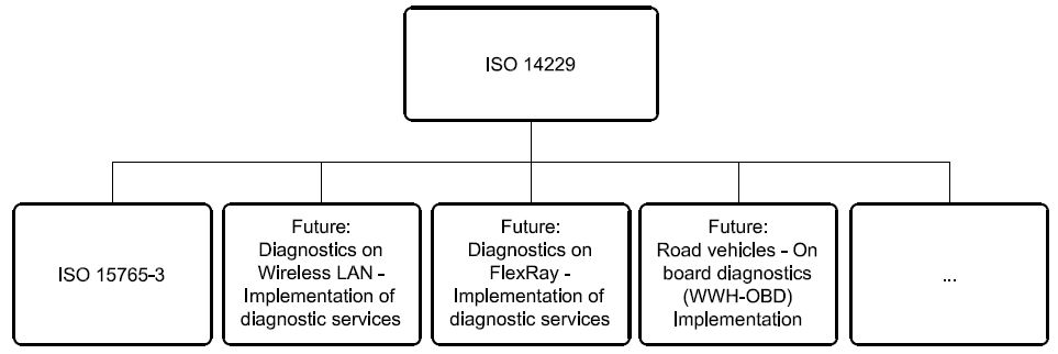
Figure 1 — Available International Standards and possible future implementations of ISO 14229
Road vehicles — Unified diagnostic services (UDS) — Specification and requirements
-
Scope
ISO 14229 specifies data link independent requirements of diagnostic services, which allow a diagnostic tester (client) to control diagnostic functions in an on-vehicle Electronic Control Unit (server) such as an electronic fuel injection, automatic gear box, anti-lock braking system, etc. connected on a serial data link embedded in a road vehicle. It specifies generic services which allow the diagnostic tester (client) to stop or to resume non- diagnostic message transmission on the data link. ISO 14229 does not apply to non-diagnostic message transmission or to use of the communication data link between two Electronic Control Units. It does not specify any implementation requirements.
The vehicle diagnostic architecture of ISO 14229 applies to:
-
a single tester (client) that may be temporarily or permanently connected to the on-vehicle diagnostic data link; and
-
several on-vehicle Electronic Control Units (servers) connected directly or indirectly.
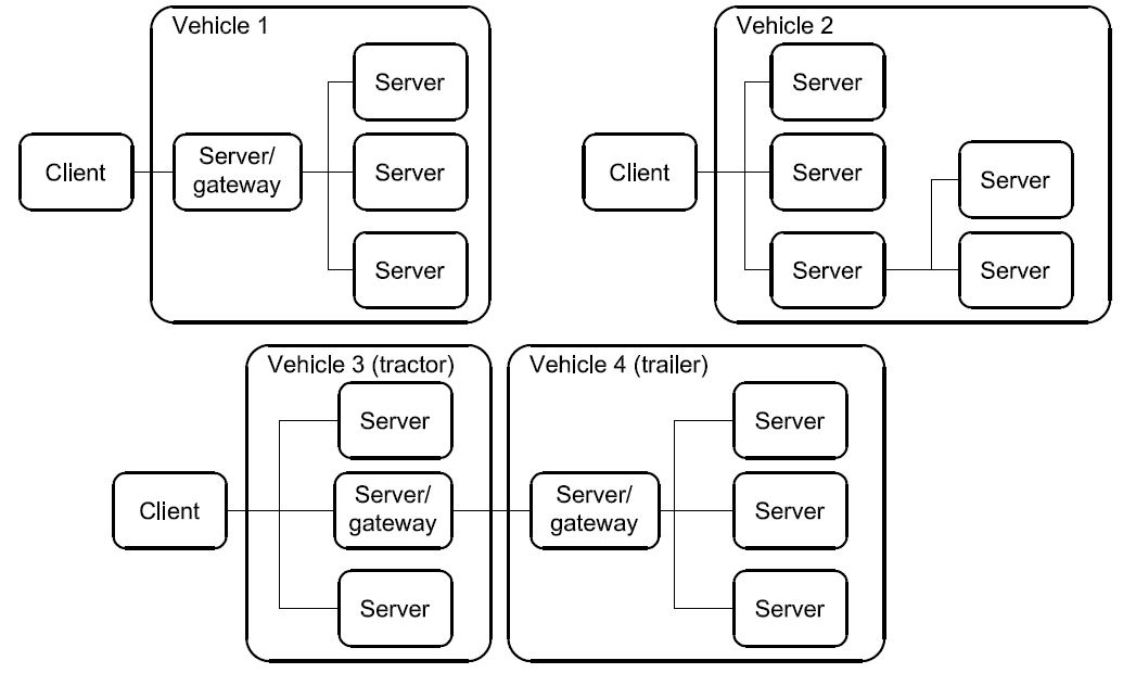
Figure 2 — Vehicle diagnostic architecture
In Figure 2:
-
For vehicle 1, the servers are connected over an internal data link and indirectly connected to the diagnostic data link through a gateway. ISO 14229 applies to the diagnostic communications over the diagnostic data link; the diagnostic communications over the internal data link may conform to ISO 14229 or to another protocol.
-
For vehicle 2, the servers are directly connected to the diagnostic data link.
-
For vehicle 3, the servers are directly connected to the diagnostic data link through a gateway (same as vehicle 2) and vehicle 4 connects its server/gateway directly to the vehicle 3 server/gateway.
-
Normative references
The following referenced documents are indispensable for the application of this document. For dated references, only the edition cited applies. For undated references, the latest edition of the referenced document (including any amendments) applies.
ISO 7498-1, Information technology — Open Systems Interconnection — Basic Reference Model: The Basic Model
ISO/IEC 10731, Information technology — Open Systems Interconnection — Basic Reference Model — Conventions for the definition of OSI services
ISO 11898 (all parts), Road vehicles — Controller area network (CAN)
ISO 11992-1, Road vehicles — Interchange of digital information on electrical connections between towing and towed vehicles — Part 1: Physical and data-link layers
ISO 11992-4, Road vehicles — Interchange of digital information on electrical connections between towing and towed vehicles — Part 4: Diagnostics
ISO 14230 (all parts), Road vehicles — Diagnostic systems — Keyword Protocol 2000
ISO 15765-2, Road vehicles — Diagnostics on Controller Area Networks (CAN) — Part 2: Network layer services
ISO 15765-3, Road vehicles — Diagnostics on Controller Area Networks (CAN) — Part 3: Implementation of unified diagnostic services (UDS on CAN)
ISO/TR 15031-2, Road vehicles — Communication between vehicle and external equipment for emissions- related diagnostics — Part 2: Terms, definitions, abbreviations and acronyms
ISO 15031-5, Road vehicles — Communication between vehicle and external equipment for emissions-related diagnostics — Part 5: Emissions-related diagnostic services
ISO 15031-6, Road vehicles — Communication between vehicle and external equipment for emissions-related diagnostics — Part 6: Diagnostic trouble code definitions
ISO 15031-7, Road vehicles — Communication between vehicle and external equipment for emissions-related diagnostics — Part 7: Data link security
ISO 15764, Road vehicles — Extended data link security
-
Terms and definitions
For the purposes of this document, the following terms and definitions apply.
3.1
integer type
simple type with distinguished values which are the positive and the negative whole numbers
NOTE The range of integer type is not specified within this document.
3.2
diagnostic trouble code
numerical common identifier for a fault condition identified by the on-board diagnostic system
3.3
diagnostic service
information exchange initiated by a client in order to require diagnostic information from a server and/or to modify its behaviour for diagnostic purposes
3.4
client
function that is part of the tester and that makes use of the diagnostic services
NOTE A tester normally makes use of other functions such as database management, specific interpretation, human- machine interface.
3.5
server
function that is part of an electronic control unit and that provides the diagnostic services
NOTE ISO 14229 differentiates between the server (i.e. the function) and the electronic control unit so that this International Standard remains independent from the implementation.
3.6
tester
system that controls functions such as test, inspection, monitoring or diagnosis of an on-vehicle electronic control unit and which may be dedicated to a specific type of operator (e.g. a scan tool dedicated to garage mechanics or a test tool dedicated to assembly plant agents)
NOTE The tester is also referenced as the client.
3.7
diagnostic data
data that is located in the memory of an electronic control unit which may be inspected and/or possibly modified by the tester (diagnostic data includes analogue inputs and outputs, digital inputs and outputs, intermediate values and various status information)
EXAMPLES Examples of diagnostic data include vehicle speed, throttle angle, mirror position, system status, etc. Three types of values are defined for diagnostic data:
-
the current value: the value currently used by (or resulting from) the normal operation of the electronic control unit;
-
a stored value: an internal copy of the current value made at specific moments, e.g. when a malfunction occurs or periodically (this copy is made under the control of the electronic control unit);
-
a static value: e.g. VIN; the server is not obliged to keep internal copies of its data for diagnostic purposes, in which case the tester may only request the current value.
3.8
diagnostic session
current mode of the server, which affects the level of diagnostic functionality
NOTE Defining a repair shop or development testing session selects different server functionality (e.g. access to all memory locations may only be allowed in the development testing session).
3.9
diagnostic routine
routine that is embedded in an electronic control unit and that may be started by a server upon a request from the client
NOTE It could either run instead of a normal operating program or run concurrently to the normal operating program. In the first case, normal operation of the ECU is not possible. In the second case, multiple diagnostic routines may be enabled that run while all other parts of the electronic control unit are functioning normally.
3.10
record
one or more diagnostic data elements that are referred to together by a single means of identification
NOTE A snapshot including various input/output data and trouble codes is an example of a record.
3.11
security
as used in ISO 14229, security access method that satisfies the requirements for tamper protection as specified in ISO 15031-7
3.12
functional unit
set of functionally close or complementary diagnostic services
3.13
local server
server that is connected to the same local network as the client and is part of the same address space as the client
3.14
local client
client that is connected to the same local network as the server and is part of the same address space as the server
3.15
remote server
server that is not directly connected to the main diagnostic network
NOTE 1 A remote server is identified by means of a remote network address. Remote network addresses represent an own network address space that is independent from the addresses on the main network.
NOTE 2 A remote server is reached via a local server on the main network. Each local server on the main network can act as a gate to one independent set of remote servers. A pair of addresses will therefore always identify a remote server: a local address that identifies the gate to the remote network and a remote address identifying the remote server itself.
3.16
remote client
client that is not directly connected to the main diagnostic network
NOTE A remote client is identified by means of a remote network address. Remote network addresses represent an own address space that is independent from the addresses on the main network.
3.17
permanent DTC
stored in NVRAM and not erasable by any test equipment command or by disconnecting power to the on-board computer
-
Symbols and abbreviated terms
A_PCI Application layer Protocol Control Information A_PDU Application layer Protocol Data Unit
A_SDU Application layer Service Data Unit ECU Electronic Control Unit
NOTE An ECU contains at least one server. Systems considered as Electronic Control Units include anti-lock braking system (ABS), engine management system, etc.
NR_SI Negative Response Service Identifier OBD On-Board Diagnostic
OSI Open Systems Interconnection
RA Remote Address
SA Source Address
SI Service Identifier
TA Target Address TA_type Target Address type
-
Conventions
ISO 14229 is guided by the conventions discussed in the OSI Service Conventions (ISO 10731) as they apply to diagnostic services. These conventions specify the interactions between the service user and the service provider. Information is passed between the service user and the service provider by service primitives, which may convey parameters.
The distinction between service and protocol is summarized in Figure 3. ISO 14229 defines both, confirmed and unconfirmed services.
-
Confirmed services use the six (6) service primitives, request, req_confirm, indication, response, rsp_confirm and confirmation.
-
Unconfirmed services use only the request, req_confirm and indication service primitives.
For all services defined in ISO 14229, the request and indication service primitives always have the same format and parameters. Consequently, for all services the response and confirmation service primitives (except req_confirm and rsp_confirm) always have the same format and parameters. When the service primitives are defined in this International Standard, only the request and response service primitives are listed.
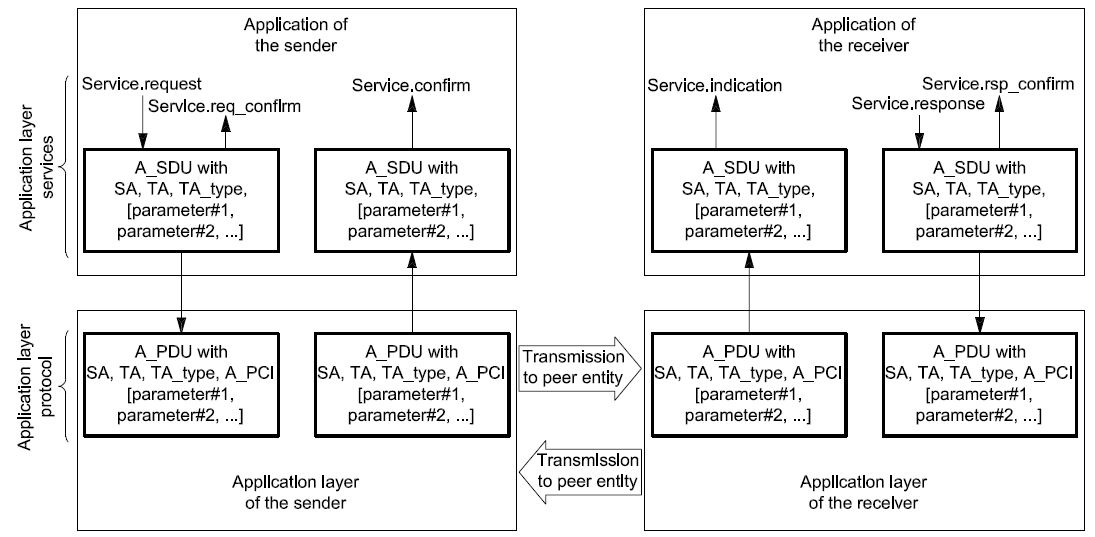
Figure 3 — The services and the protocol
-
Application layer services
-
General
Application layer services are usually referred to as diagnostic services. The application layer services are used in client-server-based systems to perform functions such as test, inspection, monitoring or diagnosis of on-board vehicle servers. The client, usually referred to as an External Test Equipment, uses the application layer services to request diagnostic functions to be performed in one or more servers. The server, usually a function that is part of an ECU, uses the application layer services to send response data, provided by the requested diagnostic service, back to the client. The client is usually an off-board tester but can, in some systems, also be an on-board tester. The usage of application layer services is independent from the client being an off-board or on-board tester. It is possible to have more than one client in the same vehicle system.
The service access point of the diagnostics application layer provides a number of services that all have the same general structure. For each service, six (6) service primitives are specified:
-
a service request primitive, used by the client function in the diagnostic tester application to pass data about a requested diagnostic service to the diagnostics application layer;
-
a service request-confirmation primitive, used by the client function in the diagnostic tester application to indicate that the data passed in the service request primitive is completely transferred to the server;
-
a service indication primitive, used by the diagnostics application layer to pass data to the server function of the ECU diagnostic application;
-
a service response primitive, used by the server function in the ECU diagnostic application to pass response data provided by the requested diagnostic service to the diagnostics application layer;
-
a service response-confirmation primitive, used by the server function in the ECU diagnostic application to indicate that the data passed in the service response primitive is completely transferred to the client;

-
a service confirmation primitive, used by the diagnostics application layer to pass data to the client function in the diagnostic tester application.
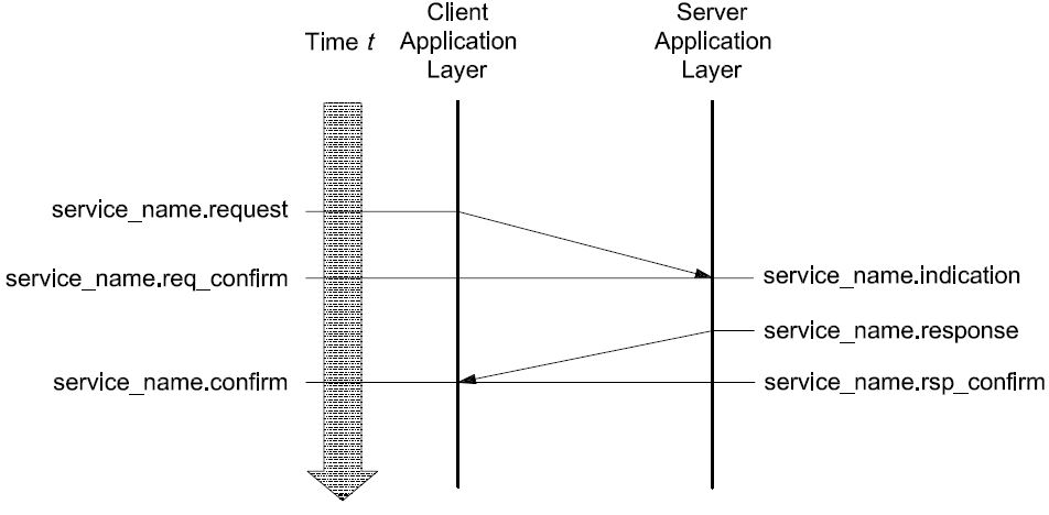
Figure 4 — Application layer service primitives — confirmed service
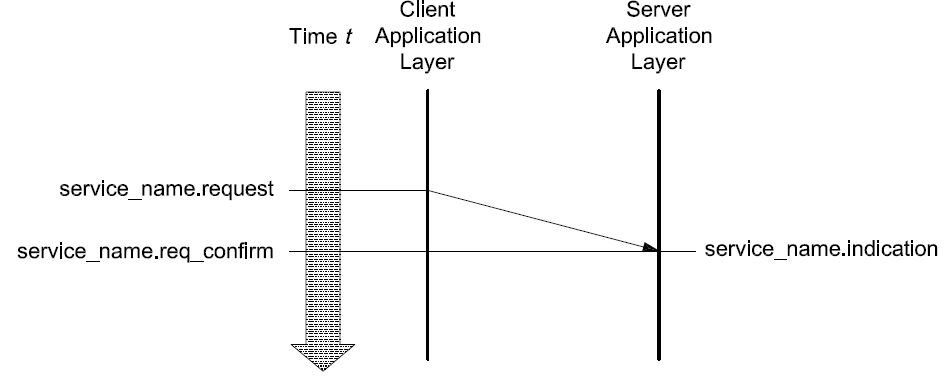
Figure 5 — Application layer service primitives — unconfirmed service
For a given service, the request primitive and the indication primitive always have the same service data unit. ISO 14229 will only list and specify the parameters of the service data unit belonging to each service request primitive. The user shall assume exactly the same parameters for each corresponding service indication primitive.
For a given service, the response primitive and the confirmation primitive always have the same service data unit. ISO 14229 only lists and specifies the parameters of the service data unit belonging to each service response primitive. The user shall assume exactly the same parameters for each corresponding service confirmation primitive.
For each service response primitive (and corresponding service confirmation primitive), two different service data units (two sets of parameters) will be specified. One set of parameters shall be used in a positive service response primitive if the requested diagnostic service can be successfully performed by the server function in the ECU diagnostic application. The other set of parameters (the negative response service data unit) shall be used if the requested diagnostic service fails or cannot be completed in time by the server function in the ECU diagnostic application.
For a given service, the request-confirmation primitive and the response-confirmation primitive always have the same service data unit. The purpose of these service primitives is to indicate the completion of an earlier request or response service primitive invocation. The service descriptions in ISO 14229 do not make use of those service primitives, but the data link specific implementation documents might use them to define e.g. service execution reference points (e.g. the ECUReset service would reset the ECU after the response has been completely transmitted to the client, which is indicated in the server by the service response-confirm primitive).
-
Format description of application layer services
Application layer services can have two different formats depending on how the vehicle diagnostic system is configured.
If the vehicle system is configured as a single (one logical) diagnostic network where all clients and servers are connected directly, then the default (also called normal or standard) format of application layer services shall be used. This format is compatible with the diagnostic system formats used on data links such as K- and L-lines. The default application layer services format is specified in 6.3.
The remote format of application layer services shall be used in vehicle systems implementing the concept of local servers and remote servers. The remote format has one additional address parameter called remote address. The remote format is used to access servers that are not directly connected to the main diagnostic network in the vehicle. The remote format for application layer services is specified in 6.4.
-
Format description of standard service primitives
-
General definition
All application layer services have the same general format. Service primitives are written in the form:
service_name.type (
parameter A, parameter B, parameter C
,parameter 1, ...
)
where:
-
“service_name” is the name of the diagnostic service (e.g. DiagnosticSessionControl);
-
“type” indicates the type of the service primitive (e.g. request);
-
“parameter A, ...” is the A_SDU as a list of values passed by the service primitive (addressing information);
-
“parameter A, parameter B, parameter C” are mandatory parameters that shall be included in all service calls;
-
“,parameter 1, ...” are parameters that depend on the specific service (e.g. parameter 1 can be the diagnosticSession for the DiagnosticSessionControl service). The brackets indicate that this part of the parameter list may be empty.
-
Service request and service indication primitives
For each application layer service, service request and service indication primitives are specified according to the following general format:
service_name.request (
SA,
TA,
TA_type
,parameter 1, ...
)
The request primitive is used by the client function in the diagnostic tester application to initiate the service and pass data about the requested diagnostic service to the application layer.
service_name.indication (
SA,
TA,
TA_type
,parameter 1, ...
)
The indication primitive is used by the application layer to indicate an internal event which is significant to the ECU diagnostic application and to pass data about the requested diagnostic service to the server function of the ECU diagnostic application.
The request and indication primitives of a specific application layer service always have the same parameters and parameter values. This means that the values of individual parameters shall not be changed by the communicating peer protocol entities of the application layer when the data is transmitted from the client to the server. The same values that are passed by the client function in the client application to the application layer in the service request call shall be received by the server function of the diagnostic application from the service indication of the peer application layer.
-
Service response and service confirm primitives
For each confirmed application layer service, service response and service confirm primitives are specified according to the following general format:
service_name.response (
SA,
TA,
TA_type, Result
,parameter 1, ...
)
The response primitive is used by the server function in the ECU diagnostic application, to initiate the service and pass response data provided by the requested diagnostic service to the application layer.
service_name.confirm (
SA,
TA,
TA_type, Result
,parameter 1, ...
)
The confirm primitive is used by the application layer to indicate an internal event which is significant to the client application and to pass results of an associated previous service request to the client function in the diagnostic tester application. It does not necessarily indicate any activity at the remote peer interface, e.g. if the requested service is not supported by the server or if the communication is broken.
The response and confirm primitives of a specific application layer service always have the same parameters and parameter values. This means that the values of individual parameters shall not be changed by the communicating peer protocol entities of the application layer when the data is transmitted from the server to the client. The same values that are passed by the server function of the ECU diagnostic application to the application layer in the service response call shall be received by the client function in the diagnostic tester application from the service confirmation of the peer application layer.
For each response and confirm primitive two different service data units (two sets of parameters) will be specified.
-
A positive response and positive confirm primitive shall be used with the first service data unit if the requested diagnostic service could be successfully performed by the server function in the ECU.
-
A negative response and confirm primitive shall be used with the second service data unit if the requested diagnostic service failed or could not be completed in time by the server function in the ECU.
-
Service request-confirm and service response-confirm primitives
For each application layer service, service request-confirm and service response-confirm primitives are specified according to the following general format:
service_name.req_confirm(
SA,
TA,
TA_type, Result
)
The request-confirm primitive is used by the application layer to indicate an internal event, which is significant to the client application, and pass results of an associated previous service request to the client function in the diagnostic tester application.
service_name.rsp_confirm(
SA,
TA,
TA_type, Result
)
The response-confirm primitive is used by the application layer to indicate an internal event, which is significant to the server application, and pass results of an associated previous service response to the server function in the ECU application.
-
Format description of remote service primitives
-
General definition
Diagnostic communication between a local client and a remote server can take place if the remote format of application layer services is used. All definitions made for the default format of application layer services shall be applicable also for the remote format of application layer services with the addition of one more addressing parameter.
Diagnostic communication can take place between a local client on the main network and one or more remote servers on a remote network. Communication can also take place between a remote client on a remote network and one or more local servers on the main network.
Diagnostic communication cannot take place between any combination of clients and servers on two different remote networks.
All remote format application layer services have the same general format. Service primitives are written in the form:
service_name.type (
parameter A, parameter B, parameter C, parameter D
,parameter 1, ...
)
where:
-
“service_name” is the name of the diagnostic service (e.g. DiagnosticSessionControl);
-
“type” indicates the type of the service primitive (e.g. request);
-
“parameter A, ...” is the A_SDU as a list of values passed by the service primitive (addressing information);
-
“parameter A, parameter B, parameter C” are mandatory parameters that shall be included in all service calls;
-
“parameter D” is an additional parameter that is only used in vehicles implementing the concept of remote servers (remote address);
-
“,parameter 1, ...” are parameters that depend on the specific service (e.g. parameter 1 can be the diagnosticSession for the DiagnosticSessionControl service). The brackets indicate that this part of the parameter list may be empty.
-
Remote service request and service indication primitives
For each remote format application layer service, service request and service indication primitives are specified according to the following general format:
service_name.request (
SA,
TA,
TA_type [,RA]
,parameter 1, ...
)
The request primitive is used by the local client function in the client application, to initiate the service and pass data about the requested diagnostic service to the application layer.
service_name.indication (
SA,
TA,
TA_type [,RA]
,parameter 1, ...
)
The indication primitive is used by the remote application layer to indicate an internal event which is significant to the ECU diagnostic application and to pass data about the requested diagnostic service to the remote server function of the ECU diagnostic application.
The request and indication primitive of a specific application layer service always have the same parameters and parameter values. This means that the values of individual parameters shall not be changed by the communicating peer protocol entities of the application layer when the data is transmitted from the client to the server. The same values that are passed by the client function in the diagnostic tester application to the application layer in the service request call shall be received by the server function of the ECU application from the service indication of the peer application layer.
NOTE For clarity, the text assumes communication between a local client and one or more remote server. The protocol also supports communication between a remote client and one or more local servers using the same remote format application layer services.
-
Remote service response and service confirm primitives
For each remote format application layer service, service response and service confirm primitives are specified according to the following general format:
service_name.response (
SA,
TA,
TA_type, [RA,]
Result
,parameter 1, ...
)
The response primitive is used by the remote server function in the ECU diagnostic application, to initiate the service and pass response data provided by the requested diagnostic service to the application layer.
service_name.confirm (
SA,
TA,
TA_type, [RA,]
Result
,parameter 1, ...
)
The confirm primitive is used by the local application layer to indicate an internal event which is significant to the client application and to pass results of an associated previous service request to the client function in the ECU application. It does not necessarily indicate any activity at the remote peer interface, e.g. if the requested service is not supported by the server or if the communication is broken.
The response and confirm primitive of a specific application layer service always has the same parameters and parameter values. This means that the values of individual parameters shall not be changed by the communicating peer protocol entities of the application layer when the data is transmitted from the server to the client. The same values that are passed by the server function of the ECU diagnostic application to the application layer in the service response call shall be received by the client function in the diagnostic tester application from the service confirmation of the peer application layer.
For each response and confirm primitive, two different service data units (two sets of parameters) will be specified.
-
A positive response and positive confirm primitive shall be used with the first service data unit if the requested diagnostic service could be successfully performed by the server function in the ECU.
-
A negative response and confirm primitive shall be used with the second service data unit if the requested diagnostic service failed or could not be completed in time by the server function in the ECU.
NOTE For clarity, the text assumes communication between a local client and one or more remote server. The protocol also supports communication between a remote client and one or more local servers using the same remote format application layer services.
-
Remote service request-confirm and service response-confirm primitives
For each application layer service, service request-confirm and service response-confirm primitives are specified according to the following general format:
service_name.req_confirm(
SA,
TA,
TA_type, [RA,]
Result
)
The request-confirm primitive is used by the client application layer to indicate an internal event which is significant to the client application and to pass results of an associated previous service request to the client function in the ECU application.
service_name.rsp_confirm(
SA,
TA, [RA,]
TA_type, Result,
)
The response-confirm primitive is used by the server application layer to indicate an internal event which is significant to the server application and to pass results of an associated previous service response to the server function in the ECU application.
-
Service data unit specification
-
Mandatory parameters
-
General definition
The application layer services contain three (3) mandatory parameters. The following parameter definitions are applicable to all application layer services specified in this International Standard (standard and remote format).
-
Source address (SA) Type: 1 byte unsigned integer value Range: 00-FF hex
Description:
The parameter SA shall be used to encode client and server identifiers, and it shall be used to represent the physical location of a client or server.
For service requests (and service indications), SA represents the client identifier for the client function that has requested the diagnostic service. The client shall always be located in one diagnostic tester only. There shall be a strict, one-to-one relation between client identifiers and source addresses. Each client identifier shall be encoded with one SA value. If more than one client is implemented in the same diagnostic tester, then each client shall have its own client identifier and corresponding SA value.
For service responses (and service confirmations), SA represents the physical location of the server that has performed the requested diagnostic service. A server may be implemented in one ECU only or be distributed and implemented in several ECUs. If a server is implemented in one ECU only, then it shall be encoded with one SA value only. If a server is distributed and implemented in several ECUs, then the server identifier shall be encoded with one SA value for each physical location of the server.
If a remote client or server is the original source for a message, then SA represents the local server that is the gate from the remote network to the main network.
NOTE The SA value in a response message will be the same as the TA value in the corresponding request message if physical addressing was used for the request message.
-
Target address (TA)
Type: 1 byte unsigned integer value Range: 00-FF hex
Description:
The parameter TA shall be used to encode client and server identifiers.
Two different addressing methods, called physical addressing and functional addressing, are specified for diagnostics. Therefore, two independent sets of target addresses can be defined for a vehicle system (one for each addressing method).
Physical addressing shall always be a dedicated message to a server implemented in one ECU. When physical addressing is used, the communication is a point-to-point communication between the client and the server.
Functional addressing is used by the client if it does not know the physical address of the server that will respond to a service request or if the server is implemented as a distributed server in several ECUs. When functional addressing is used, the communication is a broadcast communication from the client to a server implemented in one or more ECUs.
For service requests (and service indications), TA represents the server identifier for the server that will perform the requested diagnostic service. If a remote server is being addressed, then TA represents the local server that is the gate from the main network to the remote network.
For service responses (and service confirmations), TA represents the client identifier for the client that originally requested the diagnostic service and will receive the requested data. Service responses (and service confirmations) shall always use physical addressing. If a remote client is being addressed, then TA represents the local server that is the gate from the main network to the remote network.
NOTE The TA value of a response message will always be the same as the SA value of the corresponding request message.
-
TA_Type, Target Address type
Type: enumeration Range: physical, functional
Description:
The parameter TA_type is an extension to the TA parameter. It is used to represent the addressing method chosen for a message transmission.
-
Result Type: enumeration Range: positive, negative Description:
The parameter “Result” is used by the response and confirm primitives to indicate if a message is a positive response/positive confirm message or a negative response/negative confirm message. The service-specific parameters in the message are different depending on the value of the Result parameter.
-
Vehicle system requirements
The vehicle manufacturer shall ensure that each server in the system has a unique server identifier. The vehicle manufacturer shall also ensure that each client in the system has a unique client identifier.
All client and server identifiers for the main diagnostic network in a vehicle system shall be encoded into the same range of source addresses. This means that a client and a server shall not be represented by the same SA value in a given vehicle system.
The physical target address for a server shall always be the same as the source address for the server.
Remote server identifiers can be assigned independently from client and server identifiers on the main network.
In general only the server(s) addressed shall respond to the client request message.
-
Optional parameters
-
Remote address (RA) Type: 1 byte unsigned integer value Range: 00-FF hex
Description:
RA is used to extend the available address range to encode client and server identifiers. RA shall only be used in vehicles that implement the concept of local servers and remote servers. Remote addresses represent their own address range and are independent from the addresses on the main network.
The parameter RA shall be used to encode remote client and server identifiers. RA can represent either a remote target address or a remote source address, depending on the direction of the message carrying the RA.
For service requests (and service indications) sent by a client on the main network, RA represents the remote server identifier (remote target address) for the server that will perform the requested diagnostic service.
RA can be used both as a physical and a functional address. For each value of RA, the system builder shall specify if that value represents a physical or functional address.
NOTE There is no special parameter that represents physical or functional remote addresses in the way TA_type specifies the addressing method for TA. Physical and functional remote addresses share the same 1 byte range of values and the meaning of each value shall be defined by the system builder.
For service responses (and service confirmations) sent by a remote server, RA represents the physical location (remote source address) of the remote server that has performed the requested diagnostic service.
A remote server may be implemented in one ECU only or be distributed and implemented in several ECUs. If a remote server is implemented in one ECU only, then it shall be encoded with one RA value only. If a remote server is distributed and implemented in several ECUs, then the remote server identifier shall be encoded with one RA value for each physical location of the remote server.
For service requests (and service indications) sent by a remote client, RA represents the remote server identifier (remote source address) for the client function that has requested the diagnostic service.
For service responses (and service confirmations) sent by a local server, RA represents the remote client identifier (remote target address) for the client that originally requested the diagnostic service and shall receive the requested data.
-
Remote server example with remote network
In some systems, the remote server is connected to a remote network separated from the main diagnostic network by a gateway. The following is an example showing how the parameters SA, TA and RA shall be used for proper communication between a local client on the main network and a remote server via a gateway. In the example, it is assumed that the same type of addressing is used on the remote network as on the main network.
The external test equipment is connected to the main network and has client identifier 241 (F1 hex). The gateway is connected to both the main network and the remote network. On the main network the gateway has client identifier 200 (C8 hex). On the remote network, the gateway has client identifier 10 (0A hex). The remote server is connected to the remote network and has client identifier 62 (3E hex). The configuration is described in Figure 6.
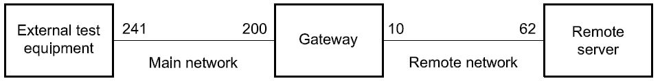
Figure 6 — Remote server system example 1
The external test equipment sends a remote diagnostic request message with
⎯ SA = 241 (F1 hex),
-
TA = 200 (C8 hex), and
⎯ RA = 62 (3E hex).
The gateway receives the message and sends it out on the remote network with
⎯ SA = 10 (0A hex),
-
TA = 62 (3E hex), and
⎯ RA = 241 (F1 hex).
The remote server receives the message.
The remote server sends back a remote diagnostic response message with
⎯ SA = 62 (3E hex),
-
TA = 10 (0A hex), and
⎯ RA = 241 (F1 hex).
The gateway receives the message and sends it out on the main network with
⎯ SA = 200 (C8 hex),
-
TA = 241 (F1 hex), and
⎯ RA = 62 (3E hex).
The external test equipment receives the message.
-
Remote server example without remote network
In some systems, the remote server is a functional part of a server belonging to the main network. The server has been given a remote server identifier in order to extend the available address range to encode client and server identifiers. In such systems the remote server is logically separated from the main network even if the ECU, of which the remote server is a part, is connected to the main diagnostic network. To get a working system, the server must also have a gateway function that is part of the main diagnostic network and can serve as a gate to the remote server. The following is an example showing how the parameters SA, TA and RA are used for proper communication between a local client on the main network and a remote server via a gateway.
The external test equipment is connected to the main network and has client identifier 241 (F1 hex). The gateway is connected to the same main network. The gateway has client identifier 200 (C8 hex). The remote server has client identifier 62 (3E hex). The configuration is described in Figure 7.
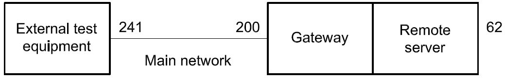
Figure 7 — Remote server system example 2
The external test equipment sends a remote diagnostic request message with
⎯ SA = 241 (F1 hex),
-
TA = 200 (C8 hex), and
⎯ RA = 62 (3E hex).
The gateway receives the message and passes it over to the remote server function. The remote server receives the message.
The remote server sends back a remote diagnostic response message by passing it to the gateway function. The gateway receives the message and sends it out on the main network with
⎯ SA = 200 (C8 hex),
-
TA = 241 (F1 hex), and
⎯ RA = 62 (3E hex).
The external test equipment receives the message.
-
Remote client example with remote network
In some systems, the client is connected to a remote network separated from the main diagnostic network by a gateway. The following is an example showing how the parameters SA, TA and RA are used for proper communication between a remote client on a remote network and a local server on the main network via a gateway. In the example, it is assumed that the same type of addressing is used on the remote network as on the main network.
The external test equipment is connected to the remote network and has client identifier 242 (F2 hex). The gateway is connected to both the main network and the remote network. On the main network, the gateway has client identifier 200 (C8 hex). On the remote network, the gateway has client identifier 10 (0A hex). The local server is connected to the main network and has client identifier 18 (12 hex). The configuration is described in Figure 8.
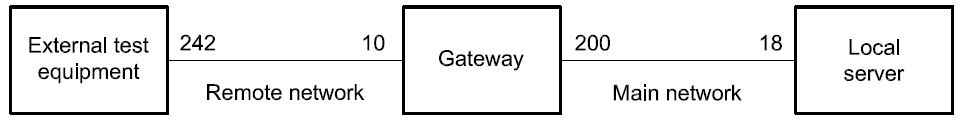
Figure 8 — Remote client example
The external test equipment sends a remote diagnostic request message with
⎯ SA = 242 (F1 hex),
-
TA = 10 (0A hex), and
⎯ RA = 18 (12 hex).
The gateway receives the message and sends it out on the main network with
-
SA = 200 dec,
-
TA = 18 dec, and
-
RA = 242 dec.
The local server receives the message.
The local server sends back a remote diagnostic response message with
⎯ SA = 18 (12 hex),
-
TA = 200 (C8 hex), and
⎯ RA = 242 (F1 hex).
The gateway receives the message and sends it out on the remote network with
⎯ SA = 10 (0A hex),
-
TA = 242 (F1 hex), and
⎯ RA = 18 (12 hex).
The external test equipment receives the message.
-
Application layer protocol
-
General definition
The application layer protocol shall always be a confirmed message transmission, meaning that for each service request sent from the client, there shall be one or more corresponding responses sent from the server.
The only exception to this rule shall be a few cases when e.g. functional addressing is used or the request/indication specifies that no response/confirmation shall be generated. In order not to burden the system with many unnecessary messages, there are a few cases when negative response messages shall not be sent even if the server failed to complete the requested diagnostic service.
The application layer protocol shall be handled in parallel with the session layer protocol. This means that, even if the client is waiting for a response to a previous request, it shall maintain proper session layer timing (e.g. sending a TesterPresent request if that is needed to keep a diagnostic session going in other servers; the implementation depends on the data link layer used).
-
Protocol data unit specification
The A_PDU is directly constructed from the A_SDU and the layer-specific control information A_PCI (Application layer Protocol Control Information). The A_PDU shall have the following general format:
A_PDU (
SA,
TA,
TA_type, [RA,]
A_Data = A_PCI + parameter 1, ...
)
where:
-
“SA, TA, TA_type, RA” are the same parameters as used in the A_SDU;
-
“A_Data” is a string of byte data defined for each individual application layer service. The A_Data string shall start with the A_PCI followed by all service-specific parameters from the A_SDU as specified for each service. The brackets indicate that this part of the parameter list may be empty.
-
Application protocol control information
The A_PCI shall have two alternative formats depending on which type of service primitive that has been called and the value of the Result parameter. For all service requests and for service responses/service confirmations with Result = positive, the following definition shall apply:
A_PCI (
SI
)
where “SI” is the parameter service identifier.

19
For service responses/service confirmations with Result = negative, the following definition shall apply:
A_PCI (
NR_SI, SI
)
where:
-
“NR_SI” is the special parameter identifying negative service responses/confirmations;
-
“SI” is the parameter service identifier.
NOTE For the transmission of periodic messages utilizing response message type #2 as defined in the service ReadDataByPeriodicIdentifier (2A hex, see 10.5) no A_PCI is present in the application layer protocol data unit (A_PDU).
-
Service identifier (SI)
Type: 1 byte unsigned integer value
Range: 00-FF hex according to definitions in Table 2
Table 2 — Service identifier (SI) values
|
Service identifier (hex value)
|
Service type (bit 6)
|
Where defined
|
|
00 – 0F
|
OBD service requests
|
ISO 15031-5
|
|
10 – 3E
|
ISO 14229 service requests
|
ISO 14229
|
|
3F
|
Not applicable
|
Reserved by document
|
|
40 – 4F
|
OBD service responses
|
ISO 15031-5
|
|
50 – 7E
|
ISO 14229 positive service responses
|
ISO 14229
|
|
7F
|
Negative response service identifier
|
ISO 14229
|
|
80
|
Not applicable
|
Reserved by ISO 14229
|
|
81 – 82
|
Not applicable
|
Reserved by ISO 14230
|
|
83 – 88
|
ISO 14229 service requests
|
ISO 14229
|
|
89 – 9F
|
Service requests
|
Reserved for future expansion as needed
|
|
A0 – B9
|
Service requests
|
Defined by vehicle manufacturer
|
|
BA – BE
|
Service requests
|
Defined by system supplier
|
|
BF
|
Not applicable
|
Reserved by document
|
|
C0
|
Not applicable
|
Reserved by ISO 14229
|
|
C1 – C2
|
Not applicable
|
Reserved by ISO 14230
|
|
C3 – C8
|
ISO 14229 positive service responses
|
ISO 14229
|
|
C9 – DF
|
Positive service responses
|
Reserved for future expansion as needed
|
|
E0 – F9
|
Positive service responses
|
Defined by vehicle manufacturer
|
|
FA – FE
|
Positive service responses
|
Defined by system supplier
|
|
FF
|
Not applicable
|
Reserved by document
|
NOTE There is a one-to-one correspondence between service identifiers for request messages and service identifiers for positive response messages, with bit 6 of the SI hex value indicating the service type. All request messages have SI bit 6 = 0. All positive response messages have SI bit 6 = 1, except response message type #2 of the ReadDataByPeriodicIdentifier (2A hex, see section 10.5) service.
Description:
The SI shall be used to encode the specific service that has been called in the service primitive. Each request service shall be assigned a unique SI value. Each positive response service shall be assigned a corresponding unique SI value.
The service identifier is used to represent the service in the A_Data data string that is passed from the application layer to lower layers (and returned from lower layers).
-
Negative response service identifier (NR_SI)
Type: 1 byte unsigned integer value Fixed value: 7F hex
Description:
The parameter NR_SI is a special parameter identifying negative service responses/confirmations. It shall be part of the A_PCI for negative response/confirm messages.
NOTE The NR_SI value is coordinated with the SI values. The NR_SI value is not used as an SI value in order to make A_Data coding and decoding easier.
-
Negative response/confirmation service primitive
Each diagnostic service has a negative response/negative confirmation message specified with message A_Data bytes according to Table 3. The first A_Data byte (A_PCI.NR_SI) is always the specific negative response service identifier. The second A_Data byte (A_PCI.SI) shall be a copy of the service identifier value from the service request/indication message to which the negative response message corresponds.
Table 3 — Negative response A_PDU
|
A_PDU parameter
|
Parameter name
|
Cvt
|
Hex value
|
Mnemonic
|
|
SA
|
Source Address
|
Ma
|
xx
|
SA
|
|
TA
|
Target Address
|
M
|
xx
|
TA
|
|
TA_type
|
Target Address type
|
M
|
xx
|
TA_type
|
|
RA
|
Remote Address (optional)
|
Cb
|
xx
|
RA
|
| |
|
A_Data.A_PCI.NR_SI
|
Negative Response Service Id
|
M
|
7F
|
SIDNR
|
|
A_Data.A_PCI.SI
|
Request Service Id
|
M
|
xx
|
SIDRQ
|
|
A_Data.Parameter 1
|
responseCode
|
M
|
xx
|
NRC_
|
| |
-
M (Mandatory): In case the negative response A_PDU is issued then those A_PDU parameters shall be present.
-
C (Conditional): The RA (Remote Address) PDU parameter is only present in case of remote addressing.
NOTE A_Data represents the message data bytes of the negative response message.
The parameter responseCode is used in the negative response message to indicate why the diagnostic service failed or could not be completed in time. Values are defined in A.1.
-
Server response implementation rules
-
General definitions
The following subclauses specify the behaviour of the server when executing a service. The server and the client shall follow these implementation rules.
Legend for subclauses 7.5.2, 7.5.3 and 7.5.4
Abbreviation Description
suppressPosRspMsgIndicationBit TRUE = server shall NOT send a positive response message
FALSE = server shall send a positive or negative response message
PosRsp Abbreviation for positive response message
NegRsp Abbreviation for negative response message
NoRsp Abbreviation for NOT sending a positive or negative response message
NRC Abbreviation for negative response code
ALL All of the requested data parameters (service without sub-function parameter) of the client request message are supported by the server
at least 1 At least 1 data parameter (service without sub-function parameter) of the client request message must be supported by the server
NONE None of the requested data parameters (service without sub-function parameter) of the client request message is supported by the server
The server shall support its list of diagnostic services regardless of addressing mode (physical, functional addressing type).
IMPORTANT — As required by the tables in the following subclauses, negative response messages with negative response codes of SNS (serviceNotSupported), SFNS (subFunctionNotSupported) and ROOR (requestOutOfRange) shall never be transmitted when functional addressing was used for the request message.
-
Request message with sub-function parameter and server response behaviour
-
Physically addressed client request message
The server response behaviour specified in this subclause is referenced in the service description of each service, which supports a sub-function parameter in the physically addressed request message received from the client.
Table 4 shows possible communication schemes with physical addressing.
Table 4 — Physically addressed request message with sub-function parameter and server response behaviour
|
Server case #
|
Client request message
|
Server capability
|
Server response
|
Comments on server response
|
|
Addressin g
scheme
|
subFunction (suppress- PosRspMsg- Indication- Bit)
|
Service ID supported
|
Sub- function supported
|
Data parameter supported (only if applicable)
|
Message
|
Negative: NRC/
section
|
|
1
|
physical
|
FALSE
(bit = 0)
|
YES
|
YES
|
At least 1
|
PosRsp
|
—
|
Server sends positive response
|
|
2
|
—
|
NegRsp
|
NRC=xx
|
Server sends negative response because error occurred reading the data parameters of the request message
|
|
3
|
NO
|
—
|
—
|
NRC=SNS
|
Negative response with NRC 11 hex
|
|
4
|
YES
|
NO
|
—
|
NRC=SFNS
|
Negative response with NRC 12 hex
|
|
5
|
TRUE
(bit = 1)
|
YES
|
YES
|
At least 1
|
NoRsp
|
—
|
Server does NOT send a response
|
|
6
|
—
|
NegRsp
|
NRC=xx
|
Server sends negative response because error occurred reading the data parameters of the request message
|
|
7
|
NO
|
—
|
—
|
NRC=SNS
|
Negative response with NRC 11 hex
|
|
8
|
YES
|
NO
|
—
|
NRC=SFNS
|
Negative response with NRC 12 hex
|
The following is a description of server response cases on physically addressed client request messages with subFunction.
-
Server sends a positive response message because the service identifier and sub-function parameter is supported by the client’s request with indication for a response message.
-
Server sends a negative response message (e.g. IMLOIF: incorrectMessageLengthOrIncorrectFormat) because the service identifier and sub-function parameter of the client's request is supported but some other error appeared (e.g. wrong PDU length according to service identifier and sub-function parameter in the request message) during processing of the sub-function.
-
Server sends a negative response message with the negative response code SNS (service not supported) because the service identifier of the client’s request is not supported with indication for a response message.
-
Server sends a negative response message with the negative response code SFNS (sub-function not supported) because the service identifier is supported and the sub-function parameter of the client's request is not supported with indication for a response message.
-
Server sends no response message because the service identifier and sub-function parameter is supported by the client’s request with indication for no response message. If a negative response code RCRRP (requestCorrectlyReceivedResponsePending) is used, a final response shall be given independent of the suppressPosRspMsgIndicationBit value.
-
Same effect as in 2) (e.g. a negative response message is sent) because the suppressPosRspMsgIndicationBit is ignored for any negative response that needs to be sent upon receipt of a physically addressed request message.
-
Same effect as in 3) (e.g. the negative response message is sent) because the suppressPosRspMsgIndicationBit is ignored for any negative response that needs to be sent upon receipt of a physically addressed request message.
-
Same effect as in 4) (e.g. the negative response message is sent) because the suppressPosRspMsgIndicationBit is ignored for any negative response that needs to be sent upon receipt of a physically addressed request message.
-
Functionally addressed client request message
The server response behaviour specified in this subclause is referenced in the service description of each service which supports a sub-function parameter in the functionally addressed request message received from the client.
Table 5 shows possible communication schemes with functional addressing.
Table 5 — Functionally addressed request message with sub-function parameter and server response behaviour
|
Server case #
|
Client request message
|
Server capability
|
Server response
|
Comments on server response
|
|
Addressing scheme
|
subFunction (suppress- PosRspMsg- Indication- Bit)
|
Service ID supported
|
Sub- function supported
|
Data parameter supported (only if applicable)
|
Message
|
Negative: NRC/
section
|
|
1
|
functional
|
FALSE
(bit = 0)
|
YES
|
YES
|
At least 1
|
PosRsp
|
—
|
Server sends positive response
|
|
2
|
At least 1
|
NegRsp
|
NRC=xx
|
Server sends negative response because error occurred reading the data parameters of the request message
|
|
3
|
None
|
NoRsp
|
—
|
Server does NOT send a response
|
|
4
|
NO
|
—
|
—
|
—
|
Server does NOT send a response
|
|
5
|
YES
|
NO
|
—
|
—
|
Server does NOT send a response
|
|
6
|
TRUE
(bit = 1)
|
YES
|
YES
|
At least 1
|
NoRsp
|
—
|
Server does NOT send a response
|
|
7
|
At least 1
|
NegRsp
|
NRC=xx
|
Server sends negative response because error occurred reading the data parameters of the request message
|
|
8
|
None
|
NoRsp
|
—
|
Server does NOT send a response
|
|
9
|
NO
|
—
|
—
|
—
|
Server does NOT send a response
|
|
10
|
YES
|
NO
|
—
|
—
|
Server does NOT send a response
|
Description of server response cases on functionally addressed client request messages with subFunction:
-
Server sends a positive response message because the service identifier and sub-function parameter is supported by the client's request with indication for a response message.
-
Server sends a negative response message (e.g. IMLOIF: incorrectMessageLengthOrIncorrectFormat) because the service identifier and sub-function parameter is supported by the client's request, but some other error appeared (e.g. wrong PDU length according to service identifier and sub-function parameter in the request message) during processing of the sub-function.
-
Server sends no response message because the negative response code ROOR (requestOutOfRange, which is identified by the server because the service identifier and sub-function parameter are supported but a required data parameter is not supported by the client's request) is always suppressed in case of a functionally addressed request message. The suppressPosRspMsgIndicationBit does not matter in such cases.
-
Server sends no response message because the negative response code SNS (serviceNotSupported, which is identified by the server because the service identifier is not supported by the client's request) is always suppressed in case of a functionally addressed request message. The suppressPosRspMsgIndicationBit does not matter in such cases.
-
Server sends no response message because the negative response code SFNS (subFunctionNotSupported, which is identified by the server because the service identifier is supported and the sub-function parameter is not supported by the client's request) is always suppressed in case of a functionally addressed request. The suppressPosRspMsgIndicationBit does not matter in such cases.
-
Server sends no response message because the service identifier and sub-function parameter is supported by the client's request with indication for no response message.
NOTE If a negative response code RCRRP (requestCorrectlyReceivedResponsePending) is used, a final response shall be given independent of the suppressPosRspMsgIndicationBit value.
-
Same effect as in 2) (e.g. a negative response message is sent) because the suppressPosRspMsgIndicationBit is ignored for any negative response. This is also true if the request message is functionally addressed.
-
Same effect as in 3) (e.g. no response message is sent) because the negative response code ROOR (requestOutOfRange, which is identified by the server because the service identifier and sub-function parameter are supported but a required data parameter is not supported by the client's request) is always suppressed in case of a functionally addressed request message. The suppressPosRspMsgIndicationBit does not matter in such a case.
-
Same effect as in 4) (e.g. no response message is sent) because the negative response code SNS (serviceNotSupported, which is identified by the server because the service identifier is not supported by the client's request) is always suppressed in case of a functionally addressed request message. The suppressPosRspMsgIndicationBit does not matter in such a case.
-
Same effect as in 5) (e.g. no response message is sent) because the negative response code SFNS (subFunctionNotSupported, which is identified by the server because the service identifier is supported and the sub-function parameter is not supported by the client's request) is always suppressed in case of a functionally addressed request message. The suppressPosRspMsgIndicationBit does not matter in such a case.
-
Request message without sub-function parameter and server response behaviour
-
Physically addressed client request message
The server response behaviour specified in this subclause is referenced in the service description of each service which does not support a sub-function parameter but a data parameter in the physically addressed request message received from the client.
Table 6 shows possible communication schemes with physical addressing.
Table 6 — Physically addressed request message without sub-function parameter and server response behaviour
|
Server case #
|
Client request message
|
Server capability
|
Server response
|
Comments on server response
|
|
Addressing scheme
|
Service ID supported
|
Parameter supported
|
Message
|
Negative: NRC/section
|
|
1
|
physical
|
YES
|
ALL
|
PosRsp
|
—
|
Server sends positive response
|
|
2
|
At least 1
|
—
|
Server sends positive response
|
|
3
|
At least 1, more than 1, or ALL
|
NegRsp
|
NRC=xx
|
Server sends negative response because error occurred reading data parameters of request message
|
|
4
|
NONE
|
NRC=ROOR
|
Negative response with NRC 31 hex
|
|
5
|
NO
|
—
|
NRC=SNS
|
Negative response with NRC 11 hex
|
The following is a description of server response cases on physically addressed client request messages without sub-function (data parameter follows service identifier).
-
Server sends a positive response message because the service identifier and all data parameters are supported by the client's request message.
-
Server sends a positive response message because the service identifier and a single data parameter is supported by the client's request message.
-
Server sends a negative response message (e.g. IMLOIF: incorrectMessageLengthOrIncorrectFormat) because the service identifier is supported and at least one, more than one or all data parameters are supported by the client's request message, but some other error occurred (e.g. wrong length of the request message) during processing of the service.
-
Server sends a negative response message with the negative response code ROOR (requestOutOfRange) because the service identifier is supported but none of the requested data parameters are supported by the client's request message.
-
Server sends a negative response message with the negative response code SNS (serviceNotSupported) because the service identifier is not supported by the client's request message.
-
Functionally addressed client request message
The server response behaviour specified in this subclause is referenced in the service description of each service which does not support a sub-function parameter but a data parameter in the functionally addressed request message received from the client.
Table 7 shows possible communication schemes with functional addressing.
Table 7 — Functionally addressed request message without sub-function parameter and server response behaviour
|
Server case #
|
Client request message
|
Server capability
|
Server response
|
Comments on server response
|
|
Addressing scheme
|
Service ID supported
|
Parameter supported
|
Message
|
Negative: NRC/section
|
|
1
|
functional
|
YES
|
YES
|
PosRsp
|
—
|
Server sends positive response
|
|
2
|
at least 1
|
—
|
Server sends positive response
|
|
3
|
At least 1,
more than 1, or ALL
|
NegRsp
|
NRC=xx
|
Server sends negative response because error occurred reading data parameters of request message
|
|
4
|
NONE
|
NoRsp
|
—
|
Server does NOT send a response
|
|
5
|
NO
|
—
|
—
|
Server does NOT send a response
|
The following is a description of server response cases on functionally addressed client request messages without sub-function (data parameter follows service identifier).
-
Server sends a positive response message because the service identifier and single data parameter is supported by the client's request message.
-
Server sends a positive response message because the service identifier and at least one data parameter is supported by the client's request message.
-
Server sends a negative response message (e.g. IMLOIF: incorrectMessageLengthOrIncorrectFormat) because the service identifier is supported and at least one, more than one or all data parameters are supported by the client's request message, but some other error occurred (e.g. wrong length of the request message) during processing of the service.
-
Server sends no response message because the negative response code ROOR (request out of range, which would occur because the service identifier is supported, but none of the requested data parameters is supported by the client's request) is always suppressed in case of a functionally addressed request.
-
Server sends no response message because the negative response code SNS (serviceNotSupported, which is identified by the server because the service identifier is not supported by the client's request) is always suppressed in case of a functionally addressed request.
-
Pseudo code example of server response behaviour
The following is a server pseudo code example to describe the logical steps a server shall perform when receiving a request from the client.
SWITCH (A_PDU.A_Data.A_PCI.SI)
{
CASE Service_with_subFunction: /* test if service with subFunction is supported */
SWITCH (A_PDU.A_Data.A_Data.Parameter1 & 0x7F) /* get subFunction parameter value without bit 7 */
{
CASE subFunction_00: /* test if subFunction parameter value is supported */
IF (message_length == expected_subFunction_message_length) THEN
: /* prepare response message */
responseCode = positiveResponse; /* positive response message; set internal NRC = 0x00 */
ELSE
responseCode = IMLOIF; /* NRC 0x13: incorrectMessageLengthOrInvalidFormat */
ENDIF BREAK;
CASE subFunction_01: /* test if subFunction parameter value is supported */
: /* prepare response message */
responseCode = positiveResponse; /* positive response message; set internal NRC = 0x00 */
:
:
:
CASE subFunction_127: /* test if subFunction parameter value is supported */
: /* prepare response message */
responseCode = positiveResponse; /* positive response message; set internal NRC = 0x00 */
BREAK; DEFAULT:
responseCode = SFNS; /* NRC 0x12: subFunctionNotSupported */
}
suppressPosRspMsgIndicationBit = (A_PDU.A_Data.Parameter1 & 0x80); /* results in either 0x00 or 0x80 */
IF ( (suppressPosRspMsgIndicationBit) && (responseCode == positiveResponse) ) THEN
/* test if positive response is required and if responseCode is positive 0x00 */
suppressResponse = TRUE; /* flag to NOT send a positive response message */
ELSE
suppressResponse = FALSE; /* flag to send the response message */
ENDIF BREAK;
CASE Service_without_subFunction: /* test if service without subFunction is supported */ suppressResponse = FALSE; /* flag to send the response message */
IF (message_length == expected_message_length) THEN
IF (A_PDU.A_Data.Parameter1 == supported) THEN /* test if data parameter following the SID is supported*/
: /* read data and prepare response message */
responseCode = positiveResponse; /* positive response message; set internal NRC = 0x00 */
ELSE
responseCode = ROOR; /* NRC 0x31: requestOutOfRange */
ENDIF ELSE
responseCode = IMLOIF; /* NRC 0x13: incorrectMessageLengthOrInvalidFormat */
ENDIF BREAK;
DEFAULT:
responseCode = SNS; /* NRC 0x11: serviceNotSupported */
}
IF (A_PDU.TA_type == functional && ((responseCode == SNS) ¦¦ (responseCode == SFNS) ¦¦ (responseCode == ROOR))) THEN
/* suppress negative response message */
ELSE
IF (suppressResponse == TRUE) THEN
/* suppress positive response message */
ELSE
/* send negative or positive response */
ENDIF ENDIF
When functional addressing is used for the request message, the negative response message with the negative response code (NRC) 78 hex, requestCorrectlyReceivedResponsePending (RCRRP), shall not be implemented if a negative response message with NRC=SNS (serviceNotSupported), NRC=SFNS (subFunctionNotSupported) or NRC=ROOR (requestOutOfRange) is the result of the PDU analysis of the received request message.
-
Multiple concurrent request messages with physical and functional addressing
A common server implementation has only one diagnostic protocol instance available in the server which can only handle one request at a time. The rule is that any received message (regardless of whether the addressing mode is physical or functional) occupies this resource until the request message is processed (with final response sent or application call without response).
There are only two (2) exceptions which have to be treated separately.
-
The keep-alive logic is used by a client to keep a previously enabled session active in one or multiple servers. Keep-Alive-Logic is defined as the functionally addressed valid TesterPresent message with SPRMIB=true and has to be processed by a bypass logic. It is up to the server to make sure that this specific message can not “block” the server’s application layer and that an immediately following addressed message can be processed.
-
If a server supports one or more legislated diagnostic requests and one of these requests is received while a non-legislated service (e.g. enhanced diagnostics) is active, then the active service shall be aborted, the default session shall be started and the legislated diagnostic service shall be processed. This requirement does not apply if the programming session is active.
-
Size of dataIdentifier (DID)
The dataIdentifier (DID) parameter has a size of two (2) bytes in all services throughout ISO 14229.
An implementation standard based on ISO 14229 shall specify the size of the dataIdentifier (DID) parameter if it does not match this International Standard.
-
Service description conventions
-
Service description
This clause defines how each diagnostic service is described in ISO 14229. It defines the general service description format of each diagnostic service.
This clause gives a brief outline of the functionality of the service. Each diagnostic service specification starts with a description of the actions performed by the client and the server(s) which are specific to each service. The description of each service includes a table which lists the parameters of its primitives: request/indication, response/confirmation for a positive or negative result. All have the same structure.
For a given request/indication and response/confirmation A_PDU definition, the presence of each parameter is described by one of the following convention (Cvt) values given in Table 8.
Table 8 — A_PDU parameter conventions
|
Type
|
Name
|
Description
|
|
M
|
Mandatory
|
The parameter shall be present in the A_PDU.
|
|
C
|
Conditional
|
The parameter can be present in the A_PDU, based on certain criteria (e.g. sub- function/parameters within the A_PDU).
|
|
S
|
Selection
|
Indicates that the parameter is mandatory (unless otherwise specified) and is a selection from a parameter list.
|
|
U
|
User option
|
The parameter may or may not be present, depending on dynamic usage by the user.
|
|
NOTE The “ Request Service Id” marked as “M” (Mandatory) shall not imply that this service must be supported by the server. The “M” only indicates the mandatory presence of this parameter in the request A_PDU if the server supports the service.
|
-
Request message
-
Request message definition
This subclause includes multiple tables which define the A_PDU (see Clause 7) parameters for the service request/indication. There might be a separate table for each sub-function parameter ($Level) if the request messages of the different sub-function parameters ($Level) differ in the structure of the A_Data parameters and cannot be specified clearly in one table.
Table 9 — Request A_PDU definition with sub-function
|
A_PDU parameter
|
Parameter name
|
Cvt
|
Hex value
|
Mnemonic
|
|
SA
|
Source Address
|
M
|
xx
|
SA
|
|
TA
|
Target Address
|
M
|
xx
|
TA
|
|
TA_type
|
Target Address type
|
M
|
xx
|
TAT
|
|
RA
|
Remote Address
|
C
|
xx
|
RA
|
| |
|
A_Data.A_PCI.SI
|
Request Service Id
|
M
|
xx
|
SIDRQ
|
|
A_Data. Parameter 1
|
sub-function = [
parameter]
|
S
|
xx
|
LEV_ PARAM
|
|
Parameter 2
:
Parameter k
|
data-parameter#1
:
data-parameter#k-1
|
U
: U
|
xx
:
xx
|
DP_…#1
:
DP_…#k-1
|
|
C: The RA (Remote Address) PDU parameter is only present in case of remote addressing.
|
Table 10 — Request A_PDU definition without sub-function
|
A_PDU parameter
|
Parameter name
|
Cvt
|
Hex value
|
Mnemonic
|
|
SA
|
Source Address
|
M
|
xx
|
SA
|
|
TA
|
Target Address
|
M
|
xx
|
TA
|
|
TA_type
|
Target Address type
|
M
|
xx
|
TAT
|
|
RA
|
Remote Address
|
C
|
xx
|
RA
|
| |
|
A_Data.A_PCI.SI
|
Request Service Id
|
M
|
xx
|
SIDRQ
|
|
A_Data. Parameter 1
:
Parameter k
|
data-parameter#1
:
data-parameter#k
|
U
: U
|
xx
:
xx
|
DP_…#1
:
DP_…#k
|
|
C: The RA (Remote Address) PDU parameter is only present in case of remote addressing.
|
In all requests/indications, the addressing information TA, SA, and TA_type is mandatory. The addressing information RA may optionally be present.
NOTE The addressing information is shown in the table above for definition purposes. Further service request/indication definitions only specify the A_Data A_PDU parameter because the A_Data A_PDU parameter represents the message data bytes of the service request/indication.
-
Request message sub-function parameter $Level (LEV_) definition
This subclause defines the sub-function $levels (LEV_) parameter(s) defined for the request/indication of the service .
This subclause does not contain any definition for cases where the described service does not use a sub- function parameter value and does not utilize the suppressPosRspMsgIndicationBit (this implicitly indicates that a response is required).
The sub-function parameter byte is divided into two parts (on bit-level) as defined in Table 11.
Table 11 — Sub-function parameter structure
|
Bit position
|
Description
|
|
7
|
suppressPosRspMsgIndicationBit
This bit indicates if a positive response message shall be suppressed by the server.
'0' = FALSE, do not suppress a positive response message (a positive response message is required).
'1' = TRUE, suppress response message (a positive response message shall not be sent; the server being addressed shall not send a positive response message).
Independent of the suppressPosRspMsgIndicationBit, negative response messages are sent by the server(s) according to the restrictions specified in 7.5.
|
|
6-0
|
sub-function parameter value
The bits 0-6 of the sub-function parameter contain the sub-function parameter value of the service (00 - 7F hex).
Each service utilizing the sub-function parameter byte, but only supporting the suppressPosRspMsgIndicationBit has to support the zeroSubFunction sub-function parameter value (00 hex).
|
The sub-function parameter value is a 7-bit value (bits 6-0 of the sub-function parameter byte) that can have multiple values to further specify the service behaviour.
Each service only supporting the suppressPosRspMsgIndicationBit has to support the zeroSubFunction (00 hex).
Services supporting sub-function parameter values in addition to the suppressPosRspMsgIndicationBit shall support the sub-function parameter values as defined in the sub-function parameter value table.
Each service contains a table that defines values for the sub-function parameter values, taking into account only the bits 0-6.
Table 12 — Request message sub-function parameter definition
|
Hex (bit 6-0)
|
Description
|
Cvt
|
Mnemonic
|
|
xx
|
sub-function#1
description of sub-function parameter#1
|
M/U
|
SUBFUNC1
|
|
:
|
:
|
:
|
:
|
|
xx
|
sub-function#m
description of sub-function parameter#m
|
M/U
|
SUBFUNCm
|
The convention (Cvt) column in the table above shall be interpreted as follows.
Table 13 — Sub-function parameter conventions
|
Type
|
Name
|
Description
|
|
M
|
Mandatory
|
The sub-function parameter has to be supported by the server if the service is supported.
|
|
U
|
User option
|
The sub-function parameter may or may not be supported by the server, depending on the usage of the service.
|
The complete sub-function parameter byte value is calculated based on the value of the suppressPosRspMsgIndicationBit and the sub-function parameter value chosen.
Table 14 — Calculation of the sub-function byte value
|
Bit 7
|
Bit 6
|
Bit 5
|
Bit 4
|
Bit 3
|
Bit 2
|
Bit 1
|
Bit 0
|
|
SuppressPosRspMsg- IndicationBit
|
Sub-function parameter value as specified in the sub-function parameter value table of the service
|
|
Resulting sub-function parameter byte value (bit 7 - 0)
|
-
Request message data parameter definition
This subclause defines the data-parameter(s) $DataParam (DP_) for the request/indication of the service
. This subclause does not contain any definition if the described service does not use any data parameter. The data parameter portion can contain multiple bytes. This subclause provides a generic description of each data parameter; detailed definitions can be found in the annexes of this document. The annexes also specify whether a data parameter shall be supported or is user-optional to be supported if the server supports the service.
Table 15 — Request message data parameter definition
|
Definition
|
|
data-parameter#1
description of data-parameter#1
|
|
:
|
|
data-parameter#n
description of data-parameter#n
|
-
Positive response message
-
Positive response message definition
This section includes multiple tables that define the A_PDU parameters for the service response/confirmation (see Clause 7 for a detailed description of the application layer protocol data unit A_PDU). There might be a separate table for each sub-function parameter $Level when the response messages of the different sub- function parameters $Level differ in the structure of the A_Data parameters.
The positive response message of a diagnostic service (if required) shall be sent after the execution of the diagnostic service. If a diagnostic service requires different handling (e.g. ECUReset service), the appropriate
description when to sent the positive response message can be found in the service description of the diagnostic service.
Table 16 — Positive response A_PDU
|
A_PDU parameter
|
Parameter name
|
Cvt
|
Hex value
|
Mnemonic
|
|
SA
|
Source Address
|
M
|
xx
|
SA
|
|
TA
|
Target Address
|
M
|
xx
|
TA
|
|
TA_type
|
Target Address type
|
M
|
xx
|
TAT
|
|
RA
|
Remote Address
|
C
|
xx
|
RA
|
| |
|
A_Data.A_PCI.SI
|
Response Service Id
|
S
|
xx
|
SIDPR
|
|
A_Data.Parameter 1
:
A_Data.Parameter n
|
data-parameter#1
:
data-parameter#n
|
U
|
xx
:
xx
|
DP_…#1
:
DP_…#n
|
|
C: The RA (Remote Address) PDU parameter is only present in case of remote addressing.
|
In all responses/confirmations, the addressing information TA, SA, and TA_type is mandatory. The addressing information RA is used if and only if remote addressing is used.
NOTE The addressing information is shown in Table 16 for definition purposes. Further service request/indication definitions only specify the A_Data A_PDU parameter because the A_Data A_PDU parameter represents the message data bytes of the service response/confirmation.
-
Positive response message data parameter definition
This subclause defines the data parameter(s) for the response/confirmation of the service . It does not contain any definition if the described service does not use any data parameter. The data parameter portion can contain multiple bytes. This subclause provides a generic description of each data parameter. Detailed definitions can be found in the annexes of this document. The annexes also specify whether a data parameter will be supported or is user-optional to be supported if the server supports the service.
Table 17 — Response data parameter definition
|
Definition
|
|
data-parameter#1
description of data-parameter#1. If the request supports a sub-function parameter byte then this parameter is an echo of the 7-bit sub-function parameter value contained within the sub-function parameter byte from the request message with bit 7 set to zero. The suppressPosRspMsgIndicationBit from the sub-function parameter byte is not echoed.
|
| |
|
data-parameter#m
description of data-parameter#m
|
-
Supported negative response codes (NRC_)
This subclause defines the negative response codes that will be implemented for this service. The circumstances under which each response code would occur are documented in Tables 18 and 19. The definition of the negative response message can be found in section 7.4. The server shall use the negative response A_PDU for the indication of an identified error condition.
The negative response codes listed in A.1 shall be used in addition to the negative response codes specified in each service description if applicable. Details can be found in A.1.
Table 18 — Supported negative response codes
|
Hex
|
Description
|
Cvt
|
Mnemonic
|
|
xx
|
NegativeResponseCode#1
1. condition#1
:
m. condition #m
|
M
|
NRC_
|
|
:
|
:
|
U
|
NRC_
|
|
xx
|
NegativeResponseCode#n
1. condition#1
:
k. condition #k
|
U
|
NRC_
|
The convention (Cvt) column in Table 18 shall be interpreted as follows:
Table 19 — Sub-function parameter conventions
|
Type
|
Name
|
Description
|
|
M
|
Mandatory
|
The negative response code shall be supported by the server if the service is supported.
|
|
U
|
User option
|
The negative response code may or may not be supported by the server, depending on the usage of the service.
|
-
Message flow examples
This subclause contains message flow examples for the service . All examples are shown on a message level (without addressing information).
Table 20 — Request message flow example
|
Message direction:
|
client server
|
|
Message type:
|
Request
|
|
A_Data byte
|
Description (all values are in hexadecimal)
|
Byte value (hex)
|
Mnemonic
|
|
#1 (A_PCI)
|
request Service Id
|
xx
|
SIDRQ
|
|
#2
:
#n
|
sub-function/data-parameter#1
:
data-parameter#m
|
xx xx
xx
|
LEV_/DP_ DP_
DP_
|
Table 21 — Positive response message flow example
|
Message direction:
|
server client
|
|
Message type:
|
Response
|
|
A_Data
|
Description (all values are in hexadecimal)
|
Byte value (hex)
|
Mnemonic
|
|
#1 (A_PCI)
|
response Service Id
|
xx
|
SIDPR
|
|
#2
:
#n
|
data-parameter#1
:
data-parameter#n-1
|
xx
:
xx
|
DP_
:
DP_
|
There might be multiple examples applicable to the service (e.g. one for each sub-function parameter $Level).
Table 22 shows a message flow example for a negative response message.
Table 22 — Negative response message flow example
|
Message direction:
|
server client
|
|
Message type:
|
Response
|
|
A_Data
|
Description (all values are in hexadecimal)
|
Byte value (hex)
|
Mnemonic
|
|
#1 (A_PCI.NR_SI)
|
Negative Response Service Id
|
7F
|
SIDRSIDNRQ
|
|
#2 (A_PCI.SI)
|
request Service Id
|
xx
|
SIDRQ
|
|
#3
|
responseCode
|
xx
|
NRC_
|
-
Diagnostic and communication management functional unit
-
Overview
Table 23 — Diagnostic and communication management functional unit
|
Service
|
Description
|
|
DiagnosticSessionControl
|
The client requests to control a diagnostic session with a server(s).
|
|
ECUReset
|
The client forces the server(s) to perform a reset.
|
|
SecurityAccess
|
The client requests to unlock a secured server(s).
|
|
CommunicationControl
|
The client requests the server to control its communication.
|
|
TesterPresent
|
The client indicates to the server(s) that it is still present.
|
|
AccessTimingParameter
|
The client uses this service to read/modify the timing parameters for an active communication.
|
|
SecuredDataTransmission
|
The client uses this service to perform data transmission with an extended data link security.
|
|
ControlDTCSetting
|
The client controls the setting of DTCs in the server.
|
|
ResponseOnEvent
|
The client requests to start an event mechanism in the server.
|
|
LinkControl
|
The client requests control of the communication baud rate.
|
-
DiagnosticSessionControl (10 hex) service
-
Service description
The DiagnosticSessionControl service is used to enable different diagnostic sessions in the server(s).
A diagnostic session enables a specific set of diagnostic services and/or functionality in the server(s). It can, furthermore, enable a data link layer dependent set of timing parameters applicable for the started session. This service provides the capability that the server(s) can report data link layer specific parameter values valid for the enabled diagnostic session (e.g. timing parameter values). The data link layer specific implementation document defines the structure and content of the optional parameter record contained in the response message of this service. The user of this International Standard shall define the exact set of services and/or functionality enabled in each diagnostic session (superset of functionality that is available in the defaultSession).
There shall always be exactly one diagnostic session active in a server. A server shall always start the default diagnostic session when powered up. If no other diagnostic session is started, then the default diagnostic session shall be running as long as the server is powered.
A server shall be capable of providing diagnostic functionality under normal operating conditions and in other operating conditions defined by the vehicle manufacturer, e.g. limp home operation condition.
If the client has requested a diagnostic session which is already running, then the server shall send a positive response message and behave as shown in Figure 9, which describes the server internal behaviour when transitioning between sessions.
Whenever the client requests a new diagnostic session, the server shall send the DiagnosticSessionControl positive response message before the timings of the new session become active in the server. Some situations may require that the new session must be entered before the positive response is sent while maintaining the old protocol timings for sending the response. If the server is not able to start the requested new diagnostic session, then it shall respond with a DiagnosticSessionControl negative response message and the current session shall continue (see diagnosticSession parameter definitions for further information on
how the server and client shall behave). There shall be only one session active at a time. A diagnostic session enables a specific set of diagnostic services and functions, which shall be defined by the vehicle manufacturer. The set of diagnostic services and diagnostic functionality in a non-default diagnostic session (excluding the programmingSession) is a superset of the functionality provided in the defaultSession, which means that the diagnostic functionality of the defaultSession is also available when switching to any non-default diagnostic session. A session can enable vehicle-manufacturer-specific services and functions which are not part of ISO 14229.
To start a new diagnostic session, a server may request that certain conditions be fulfilled. All such conditions are user-defined. An example of such a condition is the following.
-
The server may only allow a client with a certain client identifier (client diagnostic address) to start a specific new diagnostic session (e.g. a server may require that only a client having the client identifier F4 hex may start the extendedDiagnosticSession).
-
In some systems, it is desirable to change communication-timing parameters when a new diagnostic session is started. The DiagnosticSessionControl service entity can use the appropriate service primitives to change the timing parameters as specified for the underlying layers to change communication timing in the local node and potentially in the nodes the client wants to communicate with.
Figure 9 provides an overview about the diagnostic session transition and what the server will do when it transitions to another session.
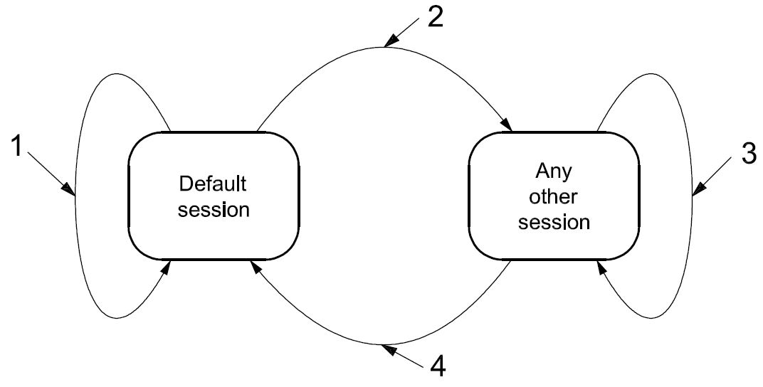
Key
-
default session
-
other session
-
same or other session
-
default session
Figure 9 — Server diagnostic session state diagram
The following is a description of diagnostic session transition:
-
When the server is in the defaultSession and the client requests to start the defaultSession, then the server shall re-initialize the defaultSession completely. The server shall reset all activated/initiated/changed settings/controls during the activated session. This does not include long-term changes programmed into non-volatile memory.
-
When the server transitions from the defaultSession to any other session than the defaultSession, then the server shall only reset the events that have been configured in the server via the ResponseOnEvent (86 hex) service during the defaultSession.
-
When the server transitions from any diagnostic session other than the defaultSession to another session other than the defaultSession (including the currently active diagnostic session), then the server shall (re-) initialize the diagnostic session, which means that each event that has been configured in the server via the ResponseOnEvent (86 hex) service shall be reset and that security shall be enabled. Any
configured periodic scheduler shall remain active when transitioning from one non-defaultSession to another or the same non-defaultSession. The states of the CommunicationControl and ControlDTCSetting services shall not be affected, which means, for example, that normal communication shall remain disabled when it is disabled at the point in time at which the session is switched.
-
When the server transitions from any diagnostic session other than the defaultSession to the defaultSession, then the server shall reset each event that has been configured in the server via the ResponseOnEvent (86 hex) service and security shall be enabled. Any configured periodic scheduler shall be disabled. Furthermore, the states of the CommunicationControl and ControlDTCSetting services shall be reset, which means, for example, that normal communication shall be re-enabled when it was disabled at the point in time the session is switched to the defaultSession. The server shall reset all activated/initiated/changed settings/controls during the activated session. This does not include long-term changes programmed into non-volatile memory.
Table 24 shows the services which are allowed during the defaultSession and the non-defaultSession (timed services). Any non-defaultSession is tied to a diagnostic session timer that has to be kept active by the client.
Table 24 — Services allowed during default and non-default diagnostic sessions
|
Service
|
defaultSession
|
non-defaultSession
|
|
DiagnosticSessionControl - 10 hex
|
x
|
x
|
|
ECUReset - 11 hex
|
x
|
x
|
|
SecurityAccess - 27 hex
|
N/A
|
x
|
|
CommunicationControl - 28 hex
|
N/A
|
x
|
|
TesterPresent - 3E hex
|
x
|
x
|
|
AccessTimingParameter - 83 hex
|
N/A
|
x
|
|
SecuredDataTransmission - 84 hex
|
N/A
|
|
|
ControlDTCSetting - 85 hex
|
N/A
|
x
|
|
ResponseOnEvent - 86 hex
|
xa
|
x
|
|
LinkControl - 87 hex
|
N/A
|
x
|
|
ReadDataByIdentifier - 22 hex
|
xb
|
x
|
|
ReadMemoryByAddress - 23 hex
|
xc
|
x
|
|
ReadScalingDataByIdentifier - 24 hex
|
xb
|
x
|
|
ReadDataByPeriodicIdentifier - 2A hex
|
N/A
|
x
|
|
DynamicallyDefineDataIdentifier - 2C hex
|
xd
|
x
|
|
WriteDataByIdentifier - 2E hex
|
xb
|
x
|
|
WriteMemoryByAddress - 3D hex
|
xc
|
x
|
|
ClearDiagnosticInformation - 14 hex
|
x
|
x
|
|
ReadDTCInformation - 19 hex
|
x
|
x
|
|
InputOutputControlByIdentifier - 2F hex
|
N/A
|
x
|
|
RoutineControl - 31 hex
|
xe
|
x
|
|
RequestDownload - 34 hex
|
N/A
|
x
|
|
RequestUpload - 35 hex
|
N/A
|
x
|
|
TransferData - 36 hex
|
N/A
|
x
|
|
RequestTransferExit - 37 hex
|
N/A
|
x
|
|
e Secured routines require a SecurityAccess service and therefore a non-default diagnostic session. A routine that needs to be stopped actively by the client also requires a non-default session.
|
-
It is implementation-specific whether the ResponseOnEvent service is also allowed during the defaultSession.
-
Secured dataIdentifiers require a SecurityAccess service and therefore a non-default diagnostic session. c Secured memory areas require a SecurityAccess service and therefore a non-default diagnostic session. d A dataIdentifier can be defined dynamically in the default and non-default diagnostic session.
IMPORTANT — The server and the client shall meet the request and response message behaviour as specified in 7.5.2 in the event that those addressing methods are implemented for this service.
-
Request message
-
Request message definition
Table 25 — Request message definition
|
A_Data byte
|
Parameter name
|
Cvt
|
Hex value
|
Mnemonic
|
|
#1
|
DiagnosticSessionControl Request Service Id
|
M
|
10
|
DSC
|
|
#2
|
sub-function = [
diagnosticSessionType ]
|
M
|
00-FF
|
LEV_
DS_
|
-
Request message sub-function parameter $Level (LEV_) definition
The sub-function parameter diagnosticSessionType is used by the DiagnosticSessionControl service to select the specific behaviour of the server. Explanations and usage of the possible diagnostic sessions are detailed below. The following sub-function values are specified [suppressPosRspMsgIndicationBit (bit 7) not shown]:
Table 26 — Request message sub-function parameter definition
|
Hex (bit 6-0)
|
Description
|
Cvt
|
Mnemonic
|
|
00
|
ISOSAEReserved
This value is reserved by ISO 14229.
|
M
|
ISOSAERESRVD
|
|
01
|
defaultSession
This diagnostic session enables the default diagnostic session in the server(s) and does not support any diagnostic application timeout handling provisions (e.g. no TesterPresent service is necessary to keep the session active).
If any other session than the defaultSession has been active in the server and the defaultSession is once again started, then the following implementation rules shall be followed (see also Figure 9).
If the used data link requires an initialization step, then the initialized server(s) shall start the default diagnostic session by default. No DiagnosticSessionControl with diagnosticSession set to defaultSession shall be required after the initialization step.
|
M
|
DS
|
-
The server shall stop the current diagnostic session when it has sent the DiagnosticSessionControl positive response message and shall start the newly requested diagnostic session afterwards.
-
If the server has sent a DiagnosticSessionControl positive response message, it shall have re-locked the server if the client unlocked it during the diagnostic session.
-
If the server sends a negative response message with the DiagnosticSessionControl request service identifier, the active session shall be continued.
Table 26 (continued)
|
Hex (bit 6-0)
|
Description
|
Cvt
|
Mnemonic
|
|
02
|
programmingSession
This diagnosticSession enables all diagnostic services required to support the memory programming of a server.
If the server runs the programmingSession in the boot software, the programmingSession shall only be left via an ECUReset (11 hex) service initiated by the client, a DiagnosticSessionControl (10 hex) service with sessionType equal to defaultSession, or a session layer timeout in the server.
If the server runs in the boot software when it receives the DiagnosticSessionControl (10 hex) service with sessionType equal to defaultSession, or a session layer timeout occurs and a valid application software is present for both cases, then the server shall restart the application software. ISO 14229 does not specify the various implementation methods of how to achieve the restart of the valid application software (e.g. a valid application software can be determined directly in the boot software, during the ECU startup phase when performing an ECUReset, etc.).
|
U
|
PRGS
|
|
03
|
extendedDiagnosticSession
This diagnosticSession can e.g. be used to enable all diagnostic services required to support the adjustment of functions such as “Idle Speed”, “CO Value”, etc. in the server's memory. It can also be used to enable diagnostic services, which are not specifically tied to the adjustment of functions.
|
U
|
EXTDS
|
|
04
|
safetySystemDiagnosticSession
This diagnosticSession enables all diagnostic services required to support safety- system-related functions e.g. airbag deployment.
|
U
|
SSDS
|
|
05 - 3F
|
ISOSAEReserved
This value is reserved by ISO 14229 for future definition.
|
M
|
ISOSAERESRVD
|
|
40 - 5F
|
vehicleManufacturerSpecific
This range of values is reserved for vehicle-manufacturer-specific use.
|
U
|
VMS
|
|
60 - 7E
|
systemSupplierSpecific
This range of values is reserved for system-supplier-specific use.
|
U
|
SSS
|
|
7F
|
ISOSAEReserved
This value is reserved by ISO 14229 for future definition.
|
M
|
ISOSAERESRVD
|
-
Request message data parameter definition
This service does not support data parameters in the request message.
-
Positive response message
-
Positive response message definition
Table 27 — Positive response message definition
|
A_Data byte
|
Parameter name
|
Cvt
|
Hex value
|
Mnemonic
|
|
#1
|
DiagnosticSessionControl Response Service Id
|
S
|
50
|
DSCPR
|
|
#2
|
diagnosticSessionType
|
M
|
00-7F
|
DS_
|
|
#3
:
#n
|
sessionParameterRecord[] #1 = [
data#1
:
data#m ]
|
Ca
: C
|
00-FF
: 00-FF
|
SPREC_ DATA_1
:
DATA_m
|
|
a C is the presence, structure and content of the sessionParameterRecord and is data-link-layer-dependant and therefore defined in the implementation specification(s) of ISO 14229.
|
-
Positive response message data parameter definition
Table 28 — Response message data parameter definition
|
Definition
|
|
diagnosticSessionType
This parameter is an echo of bits 6 - 0 of the sub-function parameter from the request message.
|
|
sessionParameterRecord
This parameter record contains session-specific parameter values reported by the server. The content and structure of this parameter record is data-link-layer-specific and can be found in the implementation specification(s) of ISO 14229.
|
-
Supported negative response codes (NRC_)
The following negative response codes shall be implemented for this service. The circumstances under which each response code occurs are documented in Table 29.
Table 29 — Supported negative response codes
|
Hex
|
Description
|
Cvt
|
Mnemonic
|
|
12
|
subFunctionNotSupported
Send if the sub-function parameter in the request message is not supported.
|
M
|
SFNS
|
|
13
|
incorrectMessageLengthOrInvalidFormat
The length of the message is wrong.
|
M
|
IMLOIF
|
|
22
|
conditionsNotCorrect
This code shall be returned if the criteria for the request DiagnosticSessionControl are not met.
|
M
|
CNC
|
-
Message flow example(s) DiagnosticSessionControl
-
Example #1 — Start programmingSession
This message flow shows how to enable the diagnostic session “programmingSession” in a server. The client requests a response message by setting the suppressPosRspMsgIndicationBit (bit 7 of the sub-function parameter) to “FALSE” (‘0’). For the given example, it is assumed that the sessionParameterRecord is supported for the data link layer for which the service is implemented.
Table 30 — DiagnosticSessionControl request message flow example #1
|
Message direction:
|
client server
|
|
Message type:
|
Request
|
|
A_Data byte
|
Description (all values are in hexadecimal)
|
Byte value (hex)
|
Mnemonic
|
|
#1
|
DiagnosticSessionControl request SID
|
10
|
DSC
|
|
#2
|
diagnosticSessionType = programmingSession, suppressPosRspMsgIndicationBit = FALSE
|
02
|
DS_ECUPRGS
|
Table 31 — DiagnosticSessionControl positive response message flow example #1
|
Message direction:
|
server client
|
|
Message type:
|
Response
|
|
A_Data byte
|
Description (all values are in hexadecimal)
|
Byte value (hex)
|
Mnemonic
|
|
#1
|
DiagnosticSessionControl response SID
|
50
|
DSCPR
|
|
#2
|
diagnosticSessionType = programmingSession
|
02
|
DS_ECUPRGS
|
-
ECUReset (11 hex) service
-
Service description
The ECUReset service is used by the client to request a server reset.
This service requests the server to effectively perform a server reset based on the content of the resetType parameter value embedded in the ECUReset request message. The ECUReset positive response message (if required) shall be sent before the reset is executed in the server(s). After a successful server reset, the server shall activate the defaultSession.
IMPORTANT — The server and the client shall meet the request and response message behaviour as specified in 7.5.2 in the event that those addressing methods are implemented for this service.
-
Request message
-
Request message definition
Table 32 — Request message definition
|
A_Data byte
|
Parameter name
|
Cvt
|
Hex value
|
Mnemonic
|
|
#1
|
ECUReset Request Service Id
|
M
|
11
|
ER
|
|
#2
|
sub-function = [
resetType ]
|
M
|
00-FF
|
LEV_
RT_
|
-
Request message sub-function Parameter $Level (LEV_) definition
The sub-function parameter resetType used by the ECUReset request message to describe how the server will perform the reset [suppressPosRspMsgIndicationBit (bit 7) is not shown].
Table 33 — Request message sub-function parameter definition
|
Hex (bit 6-0)
|
Description
|
Cvt
|
Mnemonic
|
|
00
|
ISOSAEReserved
This value is reserved by ISO 14229.
|
M
|
ISOSAERESRVD
|
|
01
|
hardReset
This value identifies a “hard reset” condition which simulates the power-on/start-up sequence typically performed after a server has been previously disconnected from its power supply (i.e. battery). The performed action is implementation specific and not defined by ISO 14229. It might result in the re-initialization of both volatile memory and non-volatile memory locations to predetermined values.
|
U
|
HR
|
|
02
|
keyOffOnReset
This value identifies a condition similar to the driver turning the ignition key off and back on. This reset condition should simulate a key-off-on sequence (i.e. interrupting the switched power supply). The performed action is implementation specific and not defined by ISO 14229. Typically, the values of non-volatile memory locations are preserved; volatile memory will be initialized.
|
U
|
KOFFONR
|
|
03
|
softReset
This value identifies a “soft reset” condition, which causes the server to immediately restart the application program if applicable. The performed action is implementation specific and not defined by ISO 14229. A typical action is to restart the application without re-initializing of previously learned configuration data, adaptive factors and other long-term adjustments.
|
U
|
SR
|
|
04
|
enableRapidPowerShutDown
This value requests the server to enable and perform a “rapid power shut down” function. The server shall execute the function immediately after “key/ignition” is switched off. While the server executes the power down function, it shall transition either directly or after a defined stand-by time to sleep mode. If the client requires a response message and the server is already prepared to execute the “rapid power shut down” function, the server shall send the positive response message prior to the start of the “rapid power shut down” function. The next occurrence of a “key on” or “ignition on” signal terminates the “rapid power shut down” function.
The client shall not send any request messages other than the ECUReset with the sub-function disableRapidPowerShutDown in order to not disturb the rapid power shut down function.
NOTE This sub-function is only applicable to a server supporting a stand-by mode!
|
U
|
ERPSD
|
|
05
|
disableRapidPowerShutDown
This value requests the server to disable the previously enabled “rapid power shut down” function.
|
U
|
DRPSD
|
|
06 - 3F
|
ISOSAEReserved
This range of values is reserved by ISO 14229 for future definition.
|
M
|
ISOSAERESRVD
|
|
40 - 5F
|
vehicleManufacturerSpecific
This range of values is reserved for vehicle-manufacturer-specific use.
|
U
|
VMS
|
|
60 - 7E
|
systemSupplierSpecific
This range of values is reserved for system-supplier-specific use.
|
U
|
SSS
|
|
7F
|
ISOSAEReserved
This value is reserved by ISO 14229 for future definition.
|
M
|
ISOSAERESRVD
|
-
Request message data parameter definition
This service does not support data parameters in the request message.
-
Positive response message
-
Positive response message definition
Table 34 — Positive response message definition
|
A_Data byte
|
Parameter name
|
Cvt
|
Hex value
|
Mnemonic
|
|
#1
|
ECUReset Response Service Id
|
S
|
51
|
ERPR
|
|
#2
|
resetType
|
M
|
00-7F
|
RT_
|
|
#3
|
powerDownTime
|
Ca
|
00-FF
|
PDT
|
|
a C: This parameter is present if the sub-function parameter is set to the enableRapidPowerShutDown value (04hex).
|
-
Positive response message data parameter definition
Table 35 — Response message data parameter definition
|
Definition
|
|
resetType
This parameter is an echo of bits 6 - 0 of the sub-function parameter from the request message.
|
|
powerDownTime
This parameter indicates to the client the minimum time of the stand-by sequence the server will remain in the power-down sequence.
The resolution of this parameter is one (1) second per count. The following values are valid:
|
-
Supported negative response codes (NRC_)
The following negative response codes shall be implemented for this service. The circumstances under which each response code would occur are documented in Table 36.
Table 36 — Supported negative response codes
|
Hex
|
Description
|
Cvt
|
Mnemonic
|
|
12
|
subFunctionNotSupported
Send if the sub-function parameter in the request message is not supported.
|
M
|
SFNS
|
|
13
|
incorrectMessageLengthOrInvalidFormat
The length of the message is wrong.
|
M
|
IMLOIF
|
|
22
|
conditionsNotCorrect
This code shall be returned if the criteria for the ECUReset request is not met.
|
M
|
CNC
|
|
33
|
securityAccessDenied
This code shall be sent if the requested reset is secured and the server is not in an unlocked state.
|
M
|
SAD
|
-
Message flow example ECUReset
This subclause specifies the conditions for the example to be fulfilled to successfully perform an ECUReset service in the server.
If the condition of server is ignition = on, the system shall not be in an operational mode (e.g. if the system is an engine management, the engine shall be off).
The client requests a response message by setting the suppressPosRspMsgIndicationBit (bit 7 of the sub- function parameter) to ‘FALSE’.
The server shall send an ECUReset positive response message before the server performs the resetType.
Table 37 — ECUReset request message flow example #1
|
Message direction:
|
client server
|
|
Message type:
|
Request
|
|
A_Data byte
|
Description (all values are in hexadecimal)
|
Byte value (hex)
|
Mnemonic
|
|
#1
|
ECUReset request SID
|
11
|
ER
|
|
#2
|
ResetType = hardReset, suppressPosRspMsgIndicationBit = FALSE
|
01
|
RT_HR
|
Table 38 — ECUReset positive response message flow example #1
|
Message direction:
|
server client
|
|
Message type:
|
Response
|
|
A_Data byte
|
Description (all values are in hexadecimal)
|
Byte value (hex)
|
Mnemonic
|
|
#1
|
ECUReset response SID
|
51
|
ERPR
|
|
#2
|
resetType = hardReset
|
01
|
RT_HR
|
-
SecurityAccess (27 hex) service
-
Service description
The purpose of this service is to provide a means to access data and/or diagnostic services which have restricted access for security, emissions or safety reasons. Diagnostic services for downloading/uploading routines or data into a server and reading specific memory locations from a server are situations where security access may be required. Improper routines or data downloaded into a server could potentially damage the electronics or other vehicle components or risk the vehicle’s compliance to emissions, safety or security standards. The security concept uses a seed and key relationship.
A typical example of the use of this service is as follows:
-
client requests the “seed”;
-
server sends the “seed”;
-
client sends the “key” (appropriate for the Seed received);
-
server responds that the “key” was valid and that it will unlock itself.
A vehicle-manufacturer-specific time delay may be required before the server can positively respond to a service SecurityAccess “requestSeed” message from the client after server power up/reset and after a certain number of false access attempts (see further description below). If this delay timer is supported, then the delay shall be activated after a vehicle-manufacturer-specified number of false access attempts has been reached or when the server is powered up/reset and a previously performed SecurityAccess service has failed due to a single false access attempt. If the server supports this delay timer, then after a successful SecurityAccess service “sendKey” execution the server internal indication information for a delay timer invocation on a power up/reset shall be cleared by the server. If the server supports this delay timer, and cannot determine if a previously performed SecurityAccess service prior to the power up/reset has failed, then the delay timer shall always be active after power up/reset. The delay is only required if the server is locked when powered up/reset. The vehicle manufacturer shall select if the delay timer is supported.
The client shall request the server to “unlock” by sending the service SecurityAccess “requestSeed” message. The server shall respond by sending a “seed” using the service SecurityAccess “requestSeed” positive response message. The client shall then respond by returning a “key” number back to the server using the appropriate service SecurityAccess “sendKey” request message. The server shall compare this “key” to one internally stored/calculated. If the two numbers match, then the server shall enable (“unlock”) the client’s access to specific services/data and indicate that with the service SecurityAccess “sendKey” positive response message. If the two numbers do not match, this shall be considered a false access attempt. If access is rejected for any other reason, it shall not be considered a false access attempt. An invalid key requires the client to start over from the beginning with a SecurityAccess “requestSeed” message.
If a server supports security, but the requested security level is already unlocked when a SecurityAccess “requestSeed” message is received, that server shall respond with a SecurityAccess “requestSeed” positive response message service with a seed value equal to zero (0). The server shall never send an all zero seed for a given security level that is currently locked. The client shall use this method to determine if a server is locked for a particular security level by checking for a non-zero seed.
There shall always be a fixed relationship for each level of security supported so that the sendKey sub-function parameter value used for any given security level shall be equal to the requestSeed sub-function parameter value used for that security level plus one.
Only one security level shall be active at any instant of time. For example, if the security level associated with requestSeed 03 hex is active, and a tester request is successful in unlocking the security level associated with requestSeed 01 hex, then only the secured functionality supported by the security level associated with requestSeed 01 hex shall be unlocked at that time. Any additional secured functionality that was previously unlocked by the security level associated with requestSeed 03 hex shall no longer be active. The security levels numbering is arbitrary and does not imply any relationship between the levels.
Attempts to access security shall not prevent normal vehicle communications or other diagnostic communication.
Servers which provide security shall support reject messages if a secure service is requested while the server is locked.
Some diagnostic functions/services requested during a specific diagnostic session may require a successful security access sequence. In such a case, the following sequence of services shall be required:
-
DiagnosticSessionControl service;
-
SecurityAccess service;
-
secured diagnostic service.
There are different accessModes allowed for an enabled diagnosticSession (session started) in the server.
IMPORTANT — The server and the client shall meet the request and response message behaviour as specified in 7.5.2 in the event that those addressing methods are implemented for this service.
-
Request message
-
Request message definition
Table 39 — Request message definition — sub-function = requestSeed
|
A_Data byte
|
Parameter name
|
Cvt
|
Hex value
|
Mnemonic
|
|
#1
|
SecurityAcces Request Service Id
|
M
|
27
|
SA
|
|
#2
|
sub-function = [
securityAccessType = requestSeed ]
|
M
|
01, 03, 05,
07-7D
|
LEV_ SAT_RSD
|
|
#3
:
#n
|
securityAccessDataRecord[] = [
parameter#1
:
parameter#m ]
|
U
: U
|
00-FF
: 00-FF
|
SECACCDR_ PARA1
: PARAm
|
Table 40 — Request message definition — sub-function = sendKey
|
A_Data byte
|
Parameter name
|
Cvt
|
Hex value
|
Mnemonic
|
|
#1
|
SecurityAcces Request Service Id
|
M
|
27
|
SA
|
|
#2
|
sub-function = [
securityAccessType = sendKey ]
|
M
|
02, 04, 06,
08-7E
|
LEV_ SAT_SK
|
|
#3
:
#n
|
securityKey[] = [
key#1 (high byte)
:
key#m (low byte) ]
|
M
: U
|
00-FF
: 00-FF
|
SECKEY_ KEY1HB
: KEYmLB
|
-
Request message sub-function parameter $Level (LEV_) definition
The sub-function parameter securityAccessType indicates to the server the step in progress for this service, the level of security the client wants to access and the format of seed and key. If a server supports different levels of security each level shall be identified by the requestSeed value, which has a fixed relationship to the sendKey value.
EXAMPLES:
-
“requestSeed=01 hex” identifies a fixed relationship between “requestSeed=01 hex” and “sendKey=02 hex”;
-
“requestSeed=03 hex” identifies a fixed relationship between “requestSeed=03 hex” and “sendKey=04 hex”.
Values are defined in Table 41 for requestSeed and sendKey [suppressPosRspMsgIndicationBit (bit 7) not shown].
Table 41 — Request message sub-function parameter definition
|
Hex (bit 6-0)
|
Description
|
Cvt
|
Mnemonic
|
|
00
|
ISOSAEReserved
This value is reserved by ISO 14229.
|
M
|
ISOSAERESRVD
|
|
01
|
requestSeed
RequestSeed with the level of security defined by the vehicle manufacturer.
|
U
|
RSD
|
|
02
|
sendKey
SendKey with the level of security defined by the vehicle manufacturer.
|
U
|
SK
|
|
03, 05,
07-41
|
requestSeed
RequestSeed with different levels of security defined by the vehicle manufacturer.
|
U
|
RSD
|
|
04, 06,
08-42
|
sendKey
SendKey with different levels of security defined by the vehicle manufacturer.
|
U
|
SK
|
|
43-5D
|
ISOSAEReserved requestSeed values
RequestSeed with different levels of security defined by ISO airbag deployment implementation standard.
|
M
|
RSD
|
|
44-5E
|
ISOSAEReserved sendKey values
SendKey with different levels of security defined by ISO airbag deployment implementation standard.
|
M
|
SK
|
|
5F
|
requestSeed value
RequestSeed security level defined in ISO Road vehicles — End of life activation of on-board pyrotechnic devices — Part 2: Communication requirements standard.
|
M
|
RSD
|
|
44-60
|
sendKey value
SendKey security level defined in ISO Road vehicles — End of life activation of on-board pyrotechnic devices — Part 2: Communication requirements standard.
|
M
|
SK
|
|
61 - 7E
|
systemSupplierSpecific
This range of values is reserved for system-supplier-specific use.
|
U
|
SSS
|
|
7F
|
ISOSAEReserved
This value is reserved by ISO 14229 for future definition.
|
M
|
ISOSAERESRVD
|
-
Request message data parameter definition
The following data parameters are defined for this service:
Table 42 — Request message data parameter definition
|
Definition
|
|
securityKey (high and low bytes)
The “key” parameter in the request message is the value generated by the security algorithm corresponding to a specific “seed” value.
|
|
securityAccessDataRecord
This parameter record is user optionally to transmit data to a server when requesting the seed information. It can e.g. contain identification of the client that is verified in the server.
|
-
Positive response message
-
Positive response message definition
Table 43 — Positive response message definition
|
A_Data byte
|
Parameter name
|
Cvt
|
Hex value
|
Mnemonic
|
|
#1
|
SecurityAccess Response Service Id
|
S
|
67
|
SAPR
|
|
#2
|
securityAccessType
|
M
|
00-7F
|
SAT_
|
|
#3
|
securityS
|
eed[] = [
seed#1 (high byte)
:
seed#m (low byte) ]
|
Ca
|
00-FF
|
SECSEED_
|
|
SEED1HB
|
|
:
|
:
|
:
|
:
|
|
#n
|
C
|
00-FF
|
SEEDmLB
|
|
a C: The presence of this parameter depends on the securityAccessType parameter. It is mandatory that it be present if the securityAccessType parameter indicates that the client wants to retrieve the seed from the server.
|
-
Positive response message data parameter definition
Table 44 — Response message data parameter definition
|
Definition
|
|
securityAccessType
This parameter is an echo of bits 6 - 0 of the sub-function parameter from the request message.
|
|
securitySeed (high and low bytes)
The seed parameter is a data value sent by the server and is used by the client when calculating the key needed to access security. The securitySeed data bytes are only present in the response message if the request message was sent with the sub-function set to a value which requests the seed of the server.
|
-
Supported negative response codes (NRC_)
The following negative response codes shall be implemented for this service. The circumstances under which each response code would occur are documented in Table 45.
Table 45 — Supported negative response codes
|
Hex
|
Description
|
Cvt
|
Mnemonic
|
|
12
|
subFunctionNotSupported
Send if the sub-function parameter in the request message is not supported.
|
M
|
SFNS
|
|
13
|
incorrectMessageLengthOrInvalidFormat
The length of the message is wrong.
|
M
|
IMLOIF
|
|
22
|
conditionsNotCorrect
This code shall be returned if the criteria for the request SecurityAccess are not met.
|
M
|
CNC
|
|
24
|
requestSequenceError
Send if the “sendKey” sub-function is received without first receiving a “requestSeed” request message.
|
M
|
RSE
|
|
31
|
requestOutOfRange
This code shall be sent if the user-optional securityAccessDataRecord contains invalid data.
|
M
|
ROOR
|
|
35
|
invalidKey
Send if an expected “sendKey” sub-function value is received and the value of the key does not match the server's internally stored/calculated key.
|
M
|
IK
|
|
36
|
exceededNumberOfAttempts
Send if the delay timer is active due to exceeding the maximum number of allowed false access attempts.
|
M
|
ENOA
|
|
37
|
requiredTimeDelayNotExpired
Send if the delay timer is active and a request is transmitted.
|
M
|
RTDNE
|
-
Message flow example(s) SecurityAccess
-
Assumptions
For the message flow examples given below, the following conditions shall be fulfilled to successfully unlock the server if it is in a “locked” state:
-
sub-function to request the seed: 01 hex (requestSeed);
-
sub-function to send the key: 02 hex (sendKey);
-
seed of the server (2 bytes): 3657 hex;
-
key of the server (2 bytes): C9A9 hex (e.g. 2’s complement of the seed value).
The client requests a response message by setting the suppressPosRspMsgIndicationBit (bit 7 of the sub- function parameter) to “FALSE” (‘0’).
-
Example #1 — server is in a “locked” state
-
Step #1: Request the seed
Table 46 — SecurityAccess request message flow example #1
|
Message direction:
|
client server
|
|
Message type:
|
Request
|
|
A_Data byte
|
Description (all values are in hexadecimal)
|
Byte value (hex)
|
Mnemonic
|
|
#1
|
SecurityAccess request SID
|
27
|
SA
|
|
#2
|
SecurityAccessType = requestSeed, suppressPosRspMsgIndicationBit = FALSE
|
01
|
SAT_RSD
|
Table 47 — SecurityAccess positive response message flow example #1
|
Message direction:
|
server client
|
|
Message type:
|
Response
|
|
A_Data byte
|
Description (all values are in hexadecimal)
|
Byte value (hex)
|
Mnemonic
|
|
#1
|
SecurityAccess response SID
|
67
|
SAPR
|
|
#2
|
securityAccessType = requestSeed
|
01
|
SAT_RSD
|
|
#3
#4
|
securitySeed [ byte#1 ] = seed #1 (high byte)
securitySeed [ byte#2 ] = seed #2 (low byte)
|
36
57
|
SECHB
SECLB
|
-
Step #2: Send the Key
Table 48 — SecurityAccess request message flow example #1
|
Message direction:
|
client server
|
|
Message type:
|
Request
|
|
A_Data byte
|
Description (all values are in hexadecimal)
|
Byte value (hex)
|
Mnemonic
|
|
#1
|
SecurityAccess request SID
|
27
|
SA
|
|
#2
|
securityAccessType = sendKey, suppressPosRspMsgIndicationBit = FALSE
|
02
|
SAT_SK
|
|
#3
#4
|
securityKey [ byte#1 ] = key #1 (high byte)
securityKey [ byte#2 ] = key #2 (low byte)
|
C9
A9
|
SECKEY_HB
SECKEY_LB
|
Table 49 — SecurityAccess positive response message flow example #1
|
Message direction:
|
server client
|
|
Message type:
|
Response
|
|
A_Data byte
|
Description (all values are in hexadecimal)
|
Byte value (hex)
|
Mnemonic
|
|
#1
|
SecurityAccess response SID
|
67
|
SAPR
|
|
#2
|
securityAccessType = sendKey
|
02
|
SAT_SK
|
-
Example #2 — server is in an “unlocked” state
-
Step #1: Request the seed
Table 50 — SecurityAccess request message flow example #1
|
Message direction:
|
client server
|
|
Message type:
|
Request
|
|
A_Data byte
|
Description (all values are in hexadecimal)
|
Byte value (hex)
|
Mnemonic
|
|
#1
|
SecurityAccess request SID
|
27
|
SA
|
|
#2
|
securityAccessType = requestSeed, suppressPosRspMsgIndicationBit = FALSE
|
01
|
SAT_RSD
|
Table 51 — SecurityAccess positive response message flow example #1
|
Message direction:
|
server client
|
|
Message type:
|
Response
|
|
A_Data byte
|
Description (all values are in hexadecimal)
|
Byte value (hex)
|
Mnemonic
|
|
#1
|
SecurityAccess response SID
|
67
|
SAPR
|
|
#2
|
securityAccessType = requestSeed
|
01
|
SAT_RSD
|
|
#3
#4
|
securitySeed [ byte#1 ] = seed #1 (high byte)
securitySeed [ byte#2 ] = seed #2 (low byte)
|
00
00
|
SECHB
SECLB
|
-
CommunicationControl (28 hex) service
-
Service description
The purpose of this service is to switch on/off the transmission and/or the reception of certain messages of (a) server(s) (e.g. application communication messages).
IMPORTANT — The server and the client shall meet the request and response message behaviour as specified in 7.5.2 in the event that those addressing methods are implemented for this service.
-
Request message
-
Request message definition
Table 52 — Request message definition
|
A_Data byte
|
Parameter name
|
Cvt
|
Hex value
|
Mnemonic
|
|
#1
|
CommunicationControl Request Service Id
|
M
|
28
|
CC
|
|
#2
|
sub-function = [
controlType ]
|
M
|
00-FF
|
LEV_ CTRLTP
|
|
#3
|
communicationType
|
M
|
00-FF
|
CTP
|
-
Request message sub-function parameter $Level (LEV_) definition
The sub-function parameter controlType contains information on how the server shall modify the communication type referenced in the communicationType parameter [suppressPosRspMsgIndicationBit (bit 7) not shown in Table 53].
Table 53 — Request message sub-function parameter definition
|
Hex (bit 6-0)
|
Description
|
Cvt
|
Mnemonic
|
|
00
|
enableRxAndTx
This value indicates that the reception and transmission of messages shall be enabled for the specified communicationType.
|
U
|
ERXTX
|
|
01
|
enableRxAndDisableTx
This value indicates that the reception of messages shall be enabled and the transmission shall be disabled for the specified communicationType.
|
U
|
ERXDTX
|
|
02
|
disableRxAndEnableTx
This value indicates that the reception of messages shall be disabled and the transmission shall be enabled for the specified communicationType.
|
U
|
DRXETX
|
|
03
|
disableRxAndTx
This value indicates that the reception and transmission of messages shall be disabled for the specified communicationType.
|
U
|
DRXTX
|
|
04 - 3F
|
ISOSAEReserved
This range of values is reserved by ISO 14229 for future definition.
|
U
|
ISOSAERESRVD
|
|
40 - 5F
|
vehicleManufacturerSpecific
This range of values is reserved for vehicle-manufacturer-specific use.
|
U
|
VMS
|
|
60 - 7E
|
systemSupplierSpecific
This range of values is reserved for system-supplier-specific use.
|
U
|
SSS
|
|
7F
|
ISOSAEReserved
This value is reserved by ISO 14229 for future definition.
|
M
|
ISOSAERESRVD
|
-
Request message data parameter definition
The following data-parameters are defined for this service:
Table 54 — Request message data parameter definition
communicationType
This parameter is used to reference the kind of communication to be controlled. The communicationType parameter is a bit-code value which allows control of multiple communication types at the same time (see B.1 for the coding of the communicationType data parameter).
-
Positive response message
-
Positive response message definition
Table 55 — Positive response message definition
|
A_Data byte
|
Parameter name
|
Cvt
|
Hex value
|
Mnemonic
|
|
#1
|
CommunicationControl Response Service Id
|
S
|
68
|
CCPR
|
|
#2
|
controlType
|
M
|
00-7F
|
CTRLTP
|
-
Positive response message data parameter definition
Table 56 — Response message data parameter definition
controlType

Definition
This parameter is an echo of bits 6 - 0 of the sub-function parameter from the request message.
-
Supported negative response codes (NRC_)
The following negative response codes shall be implemented for this service. The circumstances under which each response code would occur are documented in Table 57.
Table 57 — Supported negative response codes
|
Hex
|
Description
|
Cvt
|
Mnemonic
|
|
12
|
subFunctionNotSupported
Send if the sub-function parameter in the request message is not supported.
|
M
|
SFNS
|
|
13
|
incorrectMessageLengthOrInvalidFormat
The length of the message is wrong.
|
M
|
IMLOIF
|
|
22
|
conditionsNotCorrect
Used when the server is in a critical normal mode activity and therefore cannot disable/enable the requested communication type.
|
M
|
CNC
|
|
31
|
requestOutOfRange
The server shall use this response code if it detects an error in the communicationType parameter.
|
M
|
ROOR
|
-
Message flow example CommunicationControl (disable transmission of network management messages)
The client requests a response message by setting the suppressPosRspMsgIndicationBit (bit 7 of the sub- function parameter) to “FALSE” (‘0’).
Table 58 — CommunicationControl request message flow example
|
Message direction:
|
client server
|
|
Message type:
|
Request
|
|
A_Data byte
|
Description (all values are in hexadecimal)
|
Byte value (hex)
|
Mnemonic
|
|
#1
|
CommunicationControl request SID
|
28
|
CC
|
|
#2
|
controlType = enableRxAndDisableTx, suppressPosRspMsgIndicationBit = FALSE
|
01
|
ERXDTX
|
|
#3
|
communicationType = network management
|
02
|
NWMCP
|
Table 59 — CommunicationControl positive response message flow example
|
Message direction:
|
server client
|
|
Message type:
|
Response
|
|
A_Data byte
|
Description (all values are in hexadecimal)
|
Byte value (hex)
|
Mnemonic
|
|
#1
|
CommunicationControl response SID
|
68
|
CCPR
|
|
#2
|
ControlType
|
01
|
CTRLTP
|
-
TesterPresent (3E hex) service
-
Service description
This service is used to indicate to a server (or servers) that a client is still connected to the vehicle and that certain diagnostic services and/or communications that have been previously activated are to remain active.
This service is used to keep one or multiple servers in a diagnostic session other than the defaultSession. This can either be done by transmitting the TesterPresent request message periodically or, in case of the absence of other diagnostic services, preventing the server(s) from automatically returning to the defaultSession. The detailed session requirements that apply to the use of this service when keeping a single server or multiple servers in a diagnostic session other than the defaultSession can be found in the implementation specifications of ISO 14229.
IMPORTANT — The server and the client shall meet the request and response message behaviour as specified in 7.5.2 in the event that those addressing methods are implemented for this service.
-
Request message
-
Request message definition
Table 60 — Request message definition
|
A_Data byte
|
Parameter name
|
Cvt
|
Hex value
|
Mnemonic
|
|
#1
|
TesterPresent Request Service Id
|
M
|
3E
|
TP
|
|
#2
|
sub-function = [
zeroSubFunction ]
|
M
|
00/80
|
LEV_ ZSUBF
|
-
Request message sub-function parameter $Level (LEV_) definition
Table 61 specifies the sub-function parameter values defined for this service [suppressPosRspMsgIndicationBit (bit 7) not shown].
Table 61 — Request message sub-function parameter definition
|
Hex (bit 6-0)
|
Description
|
Cvt
|
Mnemonic
|
|
00
|
zeroSubFunction
This parameter value is used to indicate that no sub-function value beside the suppressPosRspMsgIndicationBit is supported by this service.
|
M
|
ZSUBF
|
|
01 - 7F
|
ISOSAEReserved
This range of values is reserved by ISO 14229.
|
M
|
ISOSAERESRVD
|
-
Request message data parameter definition
This service does not support data parameters in the request message.
-
Positive response message
-
Positive response message definition
Table 62 — Positive response message definition
|
A_Data byte
|
Parameter name
|
Cvt
|
Hex value
|
Mnemonic
|
|
#1
|
TesterPresent Response Service Id
|
S
|
7E
|
TPPR
|
|
#2
|
zeroSubFunction
|
M
|
00
|
ZSUBF
|
-
Positive response message data parameter definition
Table 63 — Response message data parameter definition
zeroSubFunction

Definition
This parameter is an echo of bits 6 - 0 of the sub-function parameter from the request message.
-
Supported negative response codes (NRC_)
The following negative response codes shall be implemented for this service. The circumstances under which each response code would occur are documented in Table 64.
Table 64 — Supported negative response codes
|
Hex
|
Description
|
Cvt
|
Mnemonic
|
|
12
|
subFunctionNotSupported
Send if the sub-function parameter in the request message is not supported.
|
M
|
SFNS
|
|
13
|
incorrectMessageLengthOrInvalidFormat
The length of the message is wrong.
|
M
|
IMLOIF
|
-
Message flow example(s) TesterPresent
|
Message direction:
|
client server
|
|
Message type:
|
Request
|
|
A_Data byte
|
Description (all values are in hexadecimal)
|
Byte value (hex)
|
Mnemonic
|
|
#1
|
TesterPresent request SID
|
3E
|
TP
|
|
#2
|
zeroSubFunction, suppressPosRspMsgIndicationBit = FALSE
|
00
|
ZSUBF
|
-
Example #1 — TesterPresent (suppressPosRspMsgIndicationBit = FALSE) Table 65 — TesterPresent request message flow example #1
Table 66 — TesterPresent positive response message flow example #1
|
Message direction:
|
server client
|
|
Message type:
|
Response
|
|
A_Data byte
|
Description (all values are in hexadecimal)
|
Byte value (hex)
|
Mnemonic
|
|
#1
|
TesterPresent response SID
|
7E
|
TPPR
|
|
#2
|
zeroSubFunction
|
00
|
ZSUBF
|
|
Message direction:
|
client server
|
|
Message type:
|
Request
|
|
A_Data byte
|
Description (all values are in hexadecimal)
|
Byte value (hex)
|
Mnemonic
|
|
#1
|
TesterPresent request SID
|
3E
|
TP
|
|
#2
|
zeroSubFunction, suppressPosRspMsgIndicationBit = TRUE
|
80
|
ZSUBF
|
-
Example #2 — TesterPresent (suppressPosRspMsgIndicationBit = TRUE) Table 67 — TesterPresent request message flow example #1
There is no response sent by the server(s).
-
AccessTimingParameter (83 hex) service
-
Service description
The AccessTimingParameter service is used to read and change the default timing parameters of a communication link for the duration that this communication link is active.
The use of this service is complex and depends on the server’s capability and the data link topology. Only one extended timing parameter set will be supported per diagnostic session. It is recommended to use this service only with physical addressing because of the different sets of extended timing parameters supported by the servers.
It is recommended to use the following sequence of services:
-
DiagnosticSessionControl (diagnosticSessionType) service;
-
AccessTimingParameter (readExtendedTimingParameterSet) service;
-
AccessTimingParameter (setTimingParametersToGivenValues) service.
If a response is required to be sent by the server, the client and server shall activate the new timing parameter settings after the server has sent the AccessTimingParameter positive response message. If no response message is allowed, the client and the server shall activate the new timing parameter after the transmission/reception of the request message.
The server and the client shall reset their timing parameters to the default values after a successful switching to another or the same diagnostic session (e.g. via DiagnosticSessionControl, ECUReset service or a session timing timeout).
The AccessTimingParameter service provides four (4) different modes for the access to the server timing parameters:
-
readExtendedTimingParameterSet;
-
setTimingParametersToDefaultValues;
-
readCurrentlyActiveTimingParameters;
-
setTimingParametersToGivenValues.
IMPORTANT — The server and the client shall meet the request and response message behaviour as specified in 7.5.2 in the event that those addressing methods are implemented for this service.
-
Request message
-
Request message definition
Table 68 — Request message definition
|
A_Data byte
|
Parameter name
|
Cvt
|
Hex value
|
Mnemonic
|
|
#1
|
AccessTimingParameter Request Service Id
|
M
|
83
|
ATP
|
|
#2
|
sub-func
|
tion = [
timingParameterAccessType ]
|
M
|
00-FF
|
LEV_ TPAT_
|
|
#3
|
TimingParameterRequestRecord [
byte #1
:
byte #m ]
|
Ca
|
00-FF
|
TPREQR_
|
|
B1
|
|
:
|
:
|
:
|
:
|
|
#n
|
C
|
00-FF
|
Bm
|
|
aC: The TimingParameterRequestRecord is only present if timingParameterAccessType = setTimingParametersToGivenValues. The structure and content of the TimingParameterRequestRecord is data-link-layer-dependent and therefore defined in the implementation specification(s) of ISO 14229.
|
-
Request message sub-function parameter $Level (LEV_) definition
The sub-function parameter timingParameterAccessType is used by the AccessTimingParameter service to select the specific behaviour of the server. Explanations and usage of the possible timingParameterIdentifiers are detailed below. The following sub-function values are specified [suppressPosRspMsgIndicationBit (bit 7) not shown]:
Table 69 — Request message sub-function parameter definition
|
Hex (bit 6-0)
|
Description
|
Cvt
|
Mnemonic
|
|
00
|
ISOSAEReserved
This value is reserved by ISO 14229.
|
M
|
ISOSAERESRVD
|
|
01
|
readExtendedTimingParameterSet
Upon receiving an AccessTimingParameter indication primitive with timingParameterAccessType = readExtendedTimingParameterSet, the server shall read the extended timing parameter set, i.e. the values that the server is capable of supporting.
If the read access to the timing parameter set is successful, the server shall send an AccessTimingParameter response primitive with the positive response parameters.
If the read access to the timing parameters set is not successful, the server shall send a negative response message with the appropriate negative response code.
This sub-function is used to provide an extra set of timing parameters for the currently active diagnostic session.
With the timingParameterAccessType = setTimingParametersToGivenValues only, this set (read by timingParameterAccessType = readExtendedTimingParameterSet) of timing parameters can be set.
|
U
|
RETPS
|
Table 69 (continued)
|
Hex (bit 6-0)
|
Description
|
Cvt
|
Mnemonic
|
|
02
|
setTimingParametersToDefaultValues
Upon receiving an AccessTimingParameter indication primitive with timingParameterAccessType = setTimingParametersToDefaultValues, the server shall change all timing parameters to the default values and send an AccessTimingParameter response primitive with the positive response parameters before the default timing parameters become active (if suppressPosRspMsgIndicationBit is set to 'FALSE', otherwise the timing parameters shall become active after the successful evaluation of the request message).
If the timing parameters cannot be changed to default values for any reason, the server shall maintain the currently active timing parameters and send a negative response message with the appropriate negative response code.
The definition of the default timing values depends on the used data link and is specified in the implementation specification(s) of ISO 14229.
|
U
|
STPTDV
|
|
03
|
readCurrentlyActiveTimingParameters
Upon receiving an AccessTimingParameter indication primitive with timingParameterAccessType = readCurrentlyActiveTimingParameters, the server shall read the currently used timing parameters.
If the read access to the timing parameters is successful, the server shall send an AccessTimingParameter response primitive with the positive response parameters.
If the read access to the currently used timing parameters is impossible for any reason, the server shall send a negative response message with the appropriate negative response code.
|
U
|
RCATP
|
|
04
|
setTimingParametersToGivenValues
Upon receiving an AccessTimingParameter indication primitive with timingParameterAccessType = setTimingParametersToGivenValues, the server shall check if the timing parameters can be changed under the present conditions.
If the conditions are valid, the server shall perform all actions necessary to change the timing parameters and send an AccessTimingParameter response primitive with the positive response parameters before the new timing parameter values become active (suppressPosRspMsgIndicationBit is set to 'FALSE', otherwise the timing parameters shall become active after the successful evaluation of the request message).
If the timing parameters cannot be changed for any reason, the server shall maintain the currently active timing parameters and send a negative response message with the appropriate negative response code.
It is not possible to set the timing parameters of the server to any set of values between the minimum and maximum values read via timingParameterAccessType
= readExtendedTimingParameterSet. The timing parameters of the server can only be set to exactly the timing parameters read via timingParameterAccessType = readExtendedTimingParameterSet. A request to do so shall be rejected by the server.
|
U
|
STPTGV
|
|
05-FF
|
ISOSAEReserved
This value is reserved by ISO 14229 for future definition.
|
M
|
ISOSAERESRVD
|
-
Request message data parameter definition
The following data parameters are defined for the request message:
Table 70 — Request message data parameter definition

Definition
TimingParameterRequestRecord
This parameter record contains the timing parameter values to be set in the server via timingParameterAccessType = setTimingParametersToGivenValues. The content and structure of this parameter record is data-link-layer-specific and can be found in the implementation specification(s) of ISO 14229.
-
Positive response message
-
Positive response message definition
Table 71 — Positive response message definition
|
A_Data byte
|
Parameter name
|
Cvt
|
Hex value
|
Mnemonic
|
|
#1
|
AccessTimingParameter Response Service Id
|
S
|
C3
|
ATPPR
|
|
#2
|
timingParameterAccessType
|
M
|
00-7F
|
TPAT_
|
|
#3
:
#n
|
TimingParameterResponseRecord [
byte #1
:
byte #m ]
|
C
: C
|
00-FF
: 00-FF
|
TPRSPR_ B1
:
Bm
|
|
C: The TimingParameterResponseRecord is only present if timingParameterAccessType = readExtendedTimingParameterSet or readCurrentlyActiveTimingParameters. The structure and content of the TimingParameterResponseRecord is data-link-layer-dependent and therefore defined in the implementation specification(s) of ISO 14229.
|
-
Positive response message data parameter definition
Table 72 — Response message data parameter definition
|
Definition
|
|
timingParameterAccessType
This parameter is an echo of bits 6 - 0 of the sub-function parameter from the request message.
|
|
TimingParameterResponseRecord
This parameter record contains the timing parameter values read from the server via timingParameterAccessType = readExtendedTimingParameterSet or readCurrentlyActiveTimingParameters. The content and structure of this parameter record is data-link-layer-specific and can be found in the implementation specification(s) of ISO 14229.
|
-
Supported negative response codes (NRC_)
The following negative response codes shall be implemented for this service. The circumstances under which each response code would occur are documented in Table 73.
Table 73 — Supported negative response codes
|
Hex
|
Description
|
Cvt
|
Mnemonic
|
|
12
|
subFunctionNotSupported
Send if selected timingParameterAccessType is not supported.
|
M
|
SFNS
|
|
13
|
incorrectMessageLengthOrInvalidFormat
The length of the message or the format is wrong.
|
M
|
IMLOIF
|
|
22
|
conditionsNotCorrect
This code shall be returned if the criteria for the request AccessTimingParameter are not met.
|
M
|
CNC
|
|
31
|
requestOutOfRange
This code shall be sent if the TimingParameterRequestRecord contains invalid timing parameter values.
|
M
|
ROOR
|
-
Message flow example(s) AccessTimingParameter
9.7.5.1 Example #1 — set timing parameters to default values
This message flow shows how to set the default timing parameters in a server. The client requests a response message by setting the suppressPosRspMsgIndicationBit (bit 7 of the sub-function parameter) to “FALSE” (‘0’).
Table 74 — AccessTimingParameter request message flow example #1
|
Message direction:
|
client server
|
|
Message type:
|
Request
|
|
A_Data byte
|
Description (all values are in hexadecimal)
|
Byte value (hex)
|
Mnemonic
|
|
#1
|
AccessTimingParameter request SID
|
83
|
ATP
|
|
#2
|
timingParameterAccessType = setTimingParametersToDefaultValues, suppressPosRspMsgIndicationBit = FALSE
|
02
|
TPAT_STPTDV
|
Table 75 — AccessTimingParameter positive response message flow example #1
|
Message direction:
|
server client
|
|
Message type:
|
Response
|
|
A_Data byte
|
Description (all values are in hexadecimal)
|
Byte value (hex)
|
Mnemonic
|
|
#1
|
AccessTimingParameter response SID
|
C3
|
ATPPR
|
|
#2
|
timingParameterAccessType = setTimingParametersToDefaultValues
|
02
|
TPAT_STPTDV
|
Further examples for the usage of this service can be found in the implementation specifications of ISO 14229.
-
SecuredDataTransmission (84 hex) service
-
Service description
-
Purpose
The purpose of this service is to transmit data that is protected against attacks from third parties, which could endanger data security, according to ISO 15764.
The SecuredDataTransmission service is applicable if a client intends to use diagnostic services defined in this document in a secured mode. It may also be used to transmit external data which conform to some other application protocol, in a secured mode between a client and a server. A secured mode in this context means that the data transmitted is protected by cryptographic methods.
-
Security sub-layer
This subclause briefly describes the security sub-layer as defined in ISO 15764.
Figure 10 illustrates the security sub-layer as defined in ISO 15764. The security sub-layer shall be added in the server and client application for the purpose of performing diagnostic services in a secured mode.
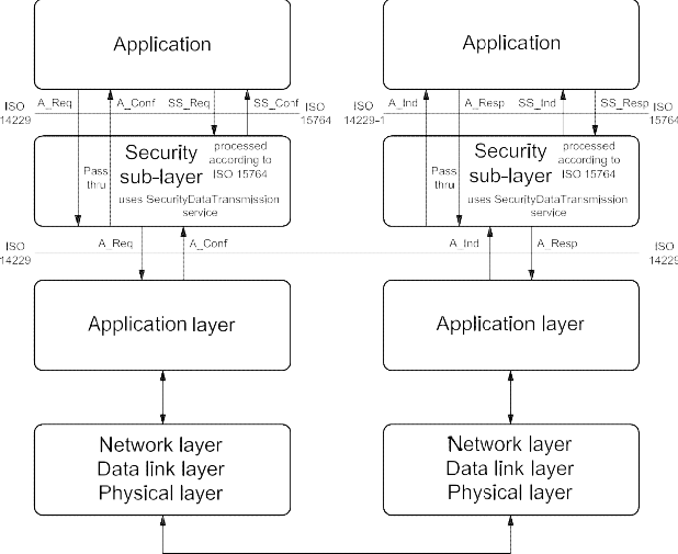
Figure 10 — Security sub-layer implementation
There are two (2) methods to perform diagnostic service data transfer between the client and server(s).
-
Unsecured data transmission mode:
The application uses the diagnostic services and application layer service primitives defined in this document to exchange data between a client and a server. The security sub-layer performs a "pass-thru" of data between "application" and "application layer" in the client and the server.
-
Secured data transmission mode:
The application uses the diagnostic services or external services and the security sub-layer service primitives defined in ISO 15764 to exchange data between a client and a server. The security sub-layer uses the SecuredDataTransmission service for the transmission/reception of the secured data. Secured links must be point-to-point communication. Therefore, only physical addressing is allowed, which means that only one server is involved.
The interface of the security sub-layer to the application is according to the ISO/OSI model conventions and therefore provides the following four (4) security sub-layer (SS_) service primitives:
-
SS_SecuredMode.req: Security sub-layer request;
-
SS_SecuredMode.ind: Security sub-layer indication;
-
SS_SecuredMode.resp: Security sub-layer response;
-
SS_SecuredMode.conf: Security sub-layer confirmation.
ISO 14229 defines both confirmed and unconfirmed services. In a secured mode, only confirmed services are allowed (suppressPosRspMsgIndicationBit = FALSE). Based on this requirement, the following services are not allowed to be executed in a secured mode:
-
ResponseOnEvent (86 hex);
-
ReadDataByPeriodicIdentifier (2A hex); and
-
TesterPresent (3E hex).
The confirmed services (suppressPosRspMsgIndicationBit = FALSE) use the four (4) application layer service primitives, request, indication, response and confirmation. Those are mapped onto the four (4) security sub-layer service primitives and vice versa when executing a confirmed diagnostic service in a secured mode.
The task of the security sub-layer when performing a diagnostic service in a secured mode is to encrypt data provided by the "application", to decrypt data provided by the "application layer" and to add, check and remove security-specific data elements. The security sub-layer uses the SecuredDataTransmission (84 hex) service of the application layer to transmit and receive the entire diagnostic message or message according to an external protocol (request and response), which shall be exchanged in a secured mode.
The security sub-layer provides the service "SecuredServiceExecution" to the application for the purpose of a secured execution of diagnostic services.
The security sub-layer request and indication primitive of the "SecuredServiceExecution" service are specified in ISO 15764 according to the following general format:
SS_SecuredMode.request (
SA,
TA,
TA_type, [RA,]
,parameter 1, ...
)
SS_SecuredMode.indication (
SA,
TA,
TA_type, [RA,]
,parameter 1, ...
)
The security sub-layer response and confirm primitive of the SecuredServiceExecution service are specified in ISO 15764 according to the following general format:
SS_SecuredMode.response (
SA,
TA,
TA_type,
RA (optional) Result,
parameter 1, ...
)
SS_SecuredMode.confirm (
SA,
TA,
TA_type,
RA (optional) Result,
parameter 1, ...
)
Detailed information can be found in ISO 15764 about:
-
the security sub-layer service primitives (Service Data Units (SDU), parameter 1, ...);
-
the security sub-layer protocol data units (PDU); and
-
the tasks to be performed by the security sub-layer for a secured data transmission.
The addressing information shown in the security sub-layer service primitives is mapped directly onto the addressing information of the application layer and vice versa.
-
Security sub-layer access
The concept of accessing the security sub-layer for a secured service execution is similar to the application layer interface as described in this document. The security sub-layer makes use of the application layer service primitives.
The following describes the execution of confirmed diagnostic service in a secured mode.
-
The client application uses the security sub-layer SecuredServiceExecution service request to perform a diagnostic service in a secured mode. The security sub-layer performs the required action to establish a link with the server(s), adds the specific security-related parameters, encrypts the service data of the diagnostic service to be executed in a secured mode if needed and uses the application layer SecuredDataTransmission service request to transmit the secured data to the server.
-
The server receives an application layer SecuredDataTransmission service indication, which is handled by the security sub-layer of the server. The security sub-layer of the server checks the security-specific parameters, decrypts encrypted data and presents the data of the service to be executed in a secured mode to the application via the security sub-layer SecuredServiceExecution service indication. The application executes the service and uses the security sub-layer SecuredServiceExecution service response to respond to the service in a secured mode. The security sub-layer of the server adds the specific security-related parameters, encrypts the response message data if needed and uses the application layer SecuredDataTransmission service response to transmit the response data to the client.
-
The client receives an application layer SecuredDataTransmission service confirmation primitive, which is handled by the security sub-layer of the client. The security sub-layer of the client checks the security-specific parameters, decrypts encrypted response data and presents the data via the security sub-layer SecuredServiceExecution confirmation to the application.
Figure 11 graphically shows the interaction of the security sub-layer, the application layer and the application when executing a confirmed diagnostic service in a secured mode.
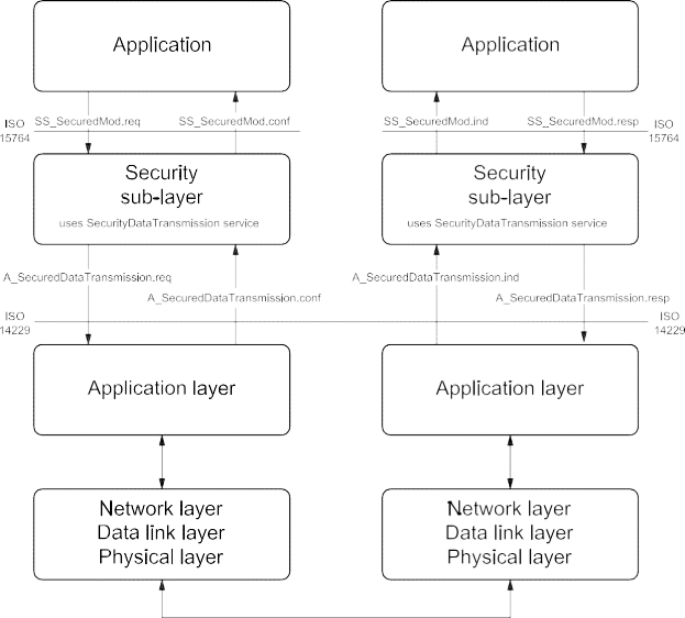
Figure 11 — Security sub-layer, application layer and application interaction
IMPORTANT — The server and the client shall meet the request and response message behaviour as specified in 7.5.3 in the event that those addressing methods are implemented for this service.
-
Request message
-
Request message definition
The security sub-layer generates the application layer SecuredDataTransmission request message parameters according to the rules defined in ISO 15764.
Table 76 — Request message definition
|
A_Data byte
|
Parameter name
|
Cvt
|
Hex value
|
Mnemonic
|
|
#1
|
SecuredDataTransmission Request Service Id
|
M
|
84
|
SDT
|
|
#2
:
#n
|
securityDataRequestRecord[] = [
securityDataParameter#1
:
securityDataParameter#m ]
|
M
: M
|
00-FF
: 00-FF
|
SECDRQR_ SDP_
: SDP_
|
-
Request message sub-function parameter $Level (LEV_) definition
This service does not use a sub-function parameter.
-
Request message data parameter definition
The following data-parameters are defined for the request message:
Table 77 — Request message data parameter definition
securityDataRequestRecord
| Definition |
|
securityDataRequestRecord
This parameter contains the data as processed by the Security Sub-Layer and is defined in ISO 15764.
|
Definition
This parameter contains the data as processed by the Security Sub-Layer and is defined in ISO 15764.
-
Positive response message
-
Positive response message definition
Table 78 — Positive response message definition
|
A_Data byte
|
Parameter name
|
Cvt
|
Hex value
|
Mnemonic
|
|
1
|
SecuredDataTransmission Response Service Id
|
M
|
C4
|
SDTPR
|
|
2
:
n
|
securityDataResponseRecord[] = [
securityDataParameter#1
:
securityDataParameter#m ]
|
M
: M
|
00-FF
: 00-FF
|
SECDRQR_ SDP_
: SDP_
|
-
Positive response message data parameter definition
The following data parameters are defined for the positive response message:
Table 79 — Response message data parameter definition
securityDataResponseRecord
| Definition |
|
securityDataResponseRecord
This parameter contains the data as processed by the Security Sub-Layer and is defined in ISO 15764.
|
Definition
This parameter contains the data as processed by the Security Sub-Layer and is defined in ISO 15764.
9.8.4 Supported negative response codes (NRC_)
The following negative response codes shall be implemented for this service. The circumstances under which each response code would occur are documented in Table 80. The response codes are always sent without encryption, even if according to the configurationProfile in the request A_PDU the response A_PDU must be encrypted.
Table 80 — Supported negative response codes
|
Hex
|
Description
|
Cvt
|
Mnemonic
|
|
13
|
incorrectMessageLengthOrInvalidFormat
The server shall use this response code if the length of the request A_PDU is not correct.
|
M
|
IMLOIF
|
|
38 - 4F
|
reservedByExtendedDataLinkSecurityDocument
This range of values is reserved by ISO 15764. Applicable negative response codes are defined in ISO 15764.
|
M
|
RBEDLSD
|
NOTE The response codes listed above apply to the SecuredDataTransmission (84 hex) service. If the diagnostic service performed in a secured mode requires a negative response, then this negative response is sent to the client in a secured mode via a SecuredDataTransmission positive response message.
-
ControlDTCSetting (85 hex) service
-
Service description
The ControlDTCSetting service shall be used by a client to stop or resume the setting of diagnostic trouble codes (DTCs) in the server(s).
The ControlDTCSetting request message can be used to stop the setting of diagnostic trouble codes in an individual server or a group of servers. If the server being addressed is not able to stop the setting of diagnostic trouble codes, it shall respond with a ControlDTCSetting negative response message indicating the reason for the rejection.
The update of the DTC status bit information shall continue once a ControlDTCSetting request is performed with sub-function set to “on” or a session layer timeout occurs (server transitions to defaultSession). The server shall still send a positive response if the service is supported in the active session with a requested sub-function set to either “on” or “off” even if the requested DTC setting state is already active.
If a clearDiagnosticInformation (14 hex) service is sent by the client, the ControlDTCSetting shall not prohibit resetting the server's DTC memory.
If a successful ECUReset is performed, then this re-enables the setting of DTCs.
IMPORTANT — The server and the client shall meet the request and response message behaviour as specified in section 7.5.2 in the event that those addressing methods are implemented for this service.
-
Request message
-
Request message definition
Table 81 — Request message definition
|
A_Data byte
|
Parameter name
|
Cvt
|
Hex value
|
Mnemonic
|
|
#1
|
ControlDTCSetting Request Service Id
|
M
|
85
|
CDTCS
|
|
#2
|
sub-func
|
tion = [
DTCSettingType ]
|
M
|
00-FF
|
LEV_ DTCSTP_
|
|
#3
:
#n
|
DTCSetti
|
ngControlOptionRecord [] =
|
[
parameter#1
:
parameter#m
|
U
: U
|
00-FF
: 00-FF
|
DTCSCOR_ PARA1
: PARAm
|
-
Request message sub-function parameter $Level (LEV_) definition
The sub-function parameter DTCSettingType is used by the ControlDTCSetting request message to indicate to the server(s) whether diagnostic trouble code setting shall stop or start again [suppressPosRspMsgIndicationBit (bit 7) not shown in Table 82].
Table 82 — Request message sub-function parameter definition
|
Hex (bit 6-0)
|
Description
|
Cvt
|
Mnemonic
|
|
00
|
ISOSAEReserved
This value is reserved by this document.
|
M
|
ISOSAERESRVD
|
|
01
|
on
The server(s) shall resume the setting of diagnostic trouble codes according to normal operating conditions.
|
M
|
ON
|
|
02
|
off
The server(s) shall stop the setting of diagnostic trouble codes.
|
M
|
OFF
|
|
03 - 3F
|
ISOSAEReserved
This range of values is reserved by this document for future definition.
|
M
|
ISOSAERESRVD
|
|
40 - 5F
|
vehicleManufacturerSpecific
This range of values is reserved for vehicle-manufacturer-specific use.
|
U
|
VMS
|
|
60 - 7E
|
systemSupplierSpecific
This range of values is reserved for system-supplier-specific use.
|
U
|
SSS
|
|
7F
|
ISOSAEReserved
This value is reserved by this document for future definition.
|
M
|
ISOSAERESRVD
|
-
Request message data parameter definition
The following data parameters are defined for this service:
Table 83 — Request message data parameter definition
| Definition |
|
DTCSettingControlOptionRecord
This parameter record is user-optional and transmits data to a server when controlling the DTC setting. It can contain a
list of DTCs to be turned on or off.
|
Definition
DTCSettingControlOptionRecord
This parameter record is user-optional and transmits data to a server when controlling the DTC setting. It can contain a list of DTCs to be turned on or off.
-
Positive response message
-
Positive response message definition
Table 84 — Positive response message definition
|
A_Data byte
|
Parameter name
|
Cvt
|
Hex value
|
Mnemonic
|
|
#1
|
ControlDTCSetting Response Service Id
|
S
|
C5
|
CDTCSPR
|
|
#2
|
DTCSettingType
|
M
|
00-7F
|
DTCSTP
|
-
Positive response message data parameter definition
Table 85 — Response message data parameter definition
DTCSettingType
| Definition |
|
DTCSettingType
This parameter is an echo of bits 6 - 0 of the sub-function parameter from the request message.
|
Definition
This parameter is an echo of bits 6 - 0 of the sub-function parameter from the request message.
-
Supported negative response codes (NRC_)
The following negative response codes shall be implemented for this service. The circumstances under which each response code would occur are documented in Table 86.
Table 86 — Supported negative response codes
|
Hex
|
Description
|
Cvt
|
Mnemonic
|
|
12
|
subFunctionNotSupported
Send if the sub-function parameter in the request message is not supported.
|
M
|
SFNS
|
|
13
|
incorrectMessageLengthOrInvalidFormat
The length of the message is wrong.
|
M
|
IMLOIF
|
|
22
|
conditionsNotCorrect
Used when the server is in a critical normal mode activity and therefore cannot perform the requested DTC control functionality.
|
U
|
CNC
|
|
31
|
requestOutOfRange
The server shall use this response DTCSettingControlOptionRecord.
|
code
|
if
|
it
|
detects
|
an
|
error
|
in
|
the
|
M
|
ROOR
|
-
Message flow example(s) ControlDTCSetting
-
Example #1 — ControlDTCSetting (DTCSettingType = off)
Note that this example does not use the capability of the service to transfer additional data to the server. The client requests to have a response message by setting the suppressPosRspMsgIndicationBit (bit 7 of the sub-function parameter) to “FALSE” (‘0’).
Table 87 — ControlDTCSetting request message flow example #1
|
Message direction:
|
client server
|
|
Message type:
|
Request
|
|
A_Data byte
|
Description (all values are in hexadecimal)
|
Byte value (hex)
|
Mnemonic
|
|
#1
|
ControlDTCSetting request SID
|
85
|
RDTCS
|
|
#2
|
DTCSettingType = off, suppressPosRspMsgIndicationBit = FALSE
|
02
|
DTCSTP_OFF
|
Table 88 — ControlDTCSetting positive response message flow example #1
|
Message direction:
|
server client
|
|
Message type:
|
Response
|
|
A_Data byte
|
Description (all values are in hexadecimal)
|
Byte value (hex)
|
Mnemonic
|
|
#1
|
ControlDTCSetting response SID
|
C5
|
RDTCSPR
|
|
#2
|
DTCSettingType = off
|
02
|
DTCSTP_OFF
|
-
Example #2 — ControlDTCSetting(suppressPosRspMsgIndicationBit= FALSE)
This example does not use the capability of the service to transfer additional data to the server. The client requests a response message by setting the suppressPosRspMsgIndicationBit (bit 7 of the sub-function parameter) to “FALSE” (‘0’).
Table 89 — ControlDTCSetting request message flow example #2
|
Message direction:
|
client server
|
|
Message type:
|
Request
|
|
A_Data byte
|
Description (all values are in hexadecimal)
|
Byte value (hex)
|
Mnemonic
|
|
#1
|
ControlDTCSetting request SID
|
85
|
ENC
|
|
#2
|
DTCSettingType = on, suppressPosRspMsgIndicationBit = FALSE
|
01
|
DTCSTP_ON
|
Table 90 — ControlDTCSetting positive response message flow example #2
|
Message direction:
|
server client
|
|
Message type:
|
Response
|
|
A_Data byte
|
Description (all values are in hexadecimal)
|
Byte value (hex)
|
Mnemonic
|
|
#1
|
ControlDTCSetting response SID
|
C5
|
RDTCSPR
|
|
#2
|
DTCSettingType = on
|
01
|
DTCSTP_ON
|
-
ResponseOnEvent (86 hex) service
-
Service description
The ResponseOnEvent service requests a server to start or stop transmission of responses on a specified event.
This service provides the possibility of automatically executing a diagnostic service in the event that a specified event occurs in the server. The client specifies the event (including optional event parameters) and the service (including service parameters) to be executed if the event occurs. See Figure 12 for a brief overview of client and server behaviour.

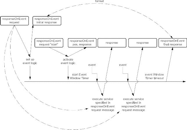
Figure 12 — ResponseOnEvent service — Client and server behaviour
NOTE Figure 12 above assumes that the event window timer is configured to timeout prior to the power down of the server, therefore the final ResponseOnEvent positive response message is shown at the end of the event timing window.
The server shall evaluate the sub-function and data content of the ResponseOnEvent request message at the time of the reception. This includes the following sub-function and parameters:
-
eventType,
-
eventWindowTime, and
-
eventTypeRecord (eventTypeParameter #1-#m).
In case of invalid data in the ResponseOnEvent request message, a negative response with the negative response code 31 hex shall be sent. The serviceToRespondToRecord is not part of this evaluation. The serviceToRespondToRecord parameter will be evaluated when the specified event occurs, which triggers the execution of the service contained in the serviceToRespondToRecord. At the time the event occurs, the serviceToRespondToRecord (diagnostic service request message) shall be executed. If conditions are not correct, a negative response message with the appropriate negative response code shall be sent. Multiple events shall be signalled in the order of their occurrence.
The following implementation rules shall apply.
-
The ResponseOnEvent service can be set up and activated in any session, including the defaultSession. TesterPresent service is not necessarily required to keep the ResponseOnEvent service active.
-
If the specified event occurs when a diagnostic service is in progress, which means that either a request message is in progress to be received, or a request is executed, or a response message is in progress (this includes the negative response message handling with response code 78 hex) to be transmitted (if suppressPosRspMsgIndicationBit = FALSE), then the execution of the request message contained in the serviceToRespondToRecord shall be postponed until the completion of the diagnostic service in progress.
If the specified event is accepted by the server, the client shall not request the following diagnostic services until the event window is passed:
The server is not executing any diagnostic service at the point in time the specified event occurs, the server executes the service contained in the serviceToRespondToRecord.
Once the ResponseOnEvent service is initiated, the server shall support the data link where this service has been submitted while the ResponseOnEvent service is active.
A DiagnosticSessionControl service shall stop the ResponseOnEvent service regardless of whether a different session than the current session or the same session is activated
It is recommended to use only the services listed in Table 91 for the service to be performed if the specified event occurs (serviceToRespondTo request service Identifier).
Table 91 — Recommended services to be used with the ResponseOnEvent service
|
Recommended services (ServiceToRespondTo)
|
Request Service Identifier (SId)
|
Response Service Identifier (SId)
|
|
ReadDataByIdentifier
|
22
|
62
|
|
ReadDTCInformation
|
19
|
59
|
|
RoutineControl
|
31
|
71
|
|
InputOutputControlByIdentifier
|
2F
|
6F
|
It is allowed to run different multiple ResponseOnEvent services at a time and to stop individual serviceToRespondTo services. While no serviceToRespondTo is currently in progress, running the server shall handle any additional diagnostic service request.
IMPORTANT — The server and the client shall meet the request and response message behaviour as specified in 7.5.2 in the event that those addressing methods are implemented for this service.
-
Request message
-
Request message definition
Table 92 — Request message definition
|
A_Data byte
|
Parameter name
|
Cvt
|
Hex value
|
Mnemonic
|
|
#1
|
ResponseOnEvent Request Service Id
|
M
|
86
|
ROE
|
|
#2
|
sub-function = [
eventType ]
|
M
|
00-FF
|
LEV_ ETP
|
|
#3
|
eventWindowTime
|
M
|
00-FF
|
EWT
|
|
#4
:
#(m-1)+4
|
eventTypeRecord[] = [
eventTypeParameter 1
:
eventTypeParameter m ]
|
Ca 1
: C1
|
00-FF
: 00-FF
|
ETR_ ETP1
: ETPm
|
|
#n-(r-1)-1
#n-(r-1)
:
#n
|
serviceToRespondToRecord[] = [
serviceId serviceParameter 1
:
serviceParameter r ]
|
Cb 2
c
C3
: C3
|
00-FF
00-FF
: 00-FF
|
STRTR_ SI SP1
:
SPr
|
| |
-
C1 is present if the eventType requires additional parameters to be specified for the event to respond to.
-
C2 shall be present if the sub-function parameter is not equal to reportActivatedEvents, stopResponseOnEvent, startResponseOnEvent, ClearResponseOnEvent.
-
C3 is present if the service request of the service to respond to requires additional service parameters.
-
Request message sub-function parameter $Level (LEV_) definition
The sub-function parameter eventType is used by the ResponseOnEvent request message to specify the event to be configured in the server and to control the ResponseOnEvent set up. Each sub-function parameter value given in Table 94 also specifies the length of the applicable eventTypeRecord [suppressPosRspMsgIndicationBit (bit 7) not shown in Table 94].
Bit 6 of the eventType sub-function parameter is used to indicate whether the event will be stored in non-volatile memory in the server and re-activated upon the next power-up of the server or if it shall terminate once the server powers down (storageState parameter).
Table 93 — eventType sub-function bit 6 definition — storageState
|
Bit 6 value
|
Description
|
Cvt
|
Mnemonic
|
|
0
|
doNotStoreEvent
This value indicates that the event shall terminate when the server powers down and the server shall not continue a ResponseOnEvent diagnostic service after a reset or power on (i.e. the ResponseOnEvent service is terminated).
|
M
|
DNSE
|
|
1
|
storeEvent
This value indicates that the event shall resume sending serviceToRespondTo responses according to the ResponseOnEvent set-up after a power cycle of the server.
|
U
|
SE
|
Table 94 — Request message sub-function parameter definition
|
Hex (bit 5-0)
|
Description
|
Cvt
|
Mnemonic
|
|
00
|
stopResponseOnEvent
This value is used to stop the server sending responses on event. The event logic that has been set up is not cleared but can be restarted with the startResponseOnEvent sub-function parameter.
Length of eventTypeRecord: 0 byte.
|
U
|
STPROE
|
|
01
|
onDTCStatusChange
This value identifies the event as a new DTC detected matching the DTCStatusMask specified for this event.
Length of eventTypeRecord: 1 byte.
Implementation hint: A server resident DTC count algorithm shall count the number of DTCs satisfying the client-defined DTCStatusMask at a certain periodic rate (e.g. approximately 1 second). If the count is different from that which was calculated on the previous execution, the client shall generate the event that causes the execution of the serviceToRespondTo. The latest count shall then be stored as a reference for the next calculation.
This eventType requires the specification of the DTCStatusMask in the request message (eventTypeParameter#1).
|
U
|
ONDTCS
|
|
02
|
onTimerInterrupt
This value identifies the event as a timer interrupt, but the timer and its values are not part of the ResponseOnEvent service.
This eventType requires the specification of more details in the request message (eventTypeRecord).
Length of eventTypeRecord: 1 byte.
|
U
|
OTI
|
|
03
|
onChangeOfDataIdentifier
This value identifies the event as a new internal data record identified by the dataIdentifier. The data values are vehicle-manufacturer-specific.
This eventType requires the specification of more details in the request message (eventTypeRecord).
Length of eventTypeRecord: 2 bytes.
|
U
|
OCODID
|
Table 94 (continued)
| Hex(bit 5-0) |
Description |
Cvt |
Mnemonic |
| 04 |
reportActivatedEvents
This value is used to indicate that in the positive response all events are reportedThis value is used to indicate that in the positive response all events are reportedthat have been activated in the server with the ResponseOnEvent service (and arecurrently active).Length of eventTypeRecord: 0 byte.
|
U |
RAE |
| 05 |
startResponseOnEvent
This value is used to indicate to the server to activate the event logic (includingThis value is used to indicate to the server to activate the event logic (includingevent window timer) that has been set up and start sending responses on event.Length of eventTypeRecord: 0 byte.
|
M |
STRTROE |
| 06 |
clearResponseOnEvent
This value is used to clear the event logic that has been set up in the server. (ThisThis value is used to clear the event logic that has been set up in the server. (Thisalso stops the server sending responses on event.)Length of eventTypeRecord: 0 byte.
|
M |
CLRROE |
| 07 |
onComparisonOfValues
This is a defined alteration of a data value out of a specific record identified by aThis is a defined alteration of a data value out of a specific record identified by adataIdentifier which identifies a data value event. With this sub-function, the usershall have the possibility of defining an event at the occurrence of a specific resultgathered from a defined measurement value comparison. A specific measurementvalue included in a data record assigned to a defined dataIdentifier is comparedwith a given comparison value. The specified operator defines the kind ofcomparison. The event occurs if the comparison result is positive.Length of eventTypeRecord: 10 bytes.
|
U |
OCOV |
| 08-1F |
ISOSAEReserved
This range of values is reserved by this document for future definition.
|
M |
ISOSAERESRVD |
| 20-2F |
VehicleManufacturerSpecific
This range of values is reserved for vehicle-manufacturer-specific use.
|
U |
VMS |
| 30-3E |
SystemSupplierSpecific
This range of values is reserved for system-supplier-specific use.
|
U |
SSS |
| 3F |
ISOSAEReserved
This value is reserved by this document for future definition.
|
M |
ISOSAERESRVD |
Hex
|
(bit 5-0)
|
|
|
04
|
reportActivatedEvents
|
U
|
RAE
|
| |
This value is used to indicate that in the positive response all events are reported that have been activated in the server with the ResponseOnEvent service (and are currently active).
|
|
|
| |
Length of eventTypeRecord: 0 byte.
|
|
|
|
05
|
startResponseOnEvent
|
M
|
STRTROE
|
| |
This value is used to indicate to the server to activate the event logic (including event window timer) that has been set up and start sending responses on event.
|
|
|
| |
Length of eventTypeRecord: 0 byte.
|
|
|
|
06
|
clearResponseOnEvent
|
M
|
CLRROE
|
| |
This value is used to clear the event logic that has been set up in the server. (This also stops the server sending responses on event.)
|
|
|
| |
Length of eventTypeRecord: 0 byte.
|
|
|
|
07
|
onComparisonOfValues
|
U
|
OCOV
|
| |
This is a defined alteration of a data value out of a specific record identified by a dataIdentifier which identifies a data value event. With this sub-function, the user shall have the possibility of defining an event at the occurrence of a specific result gathered from a defined measurement value comparison. A specific measurement value included in a data record assigned to a defined dataIdentifier is compared with a given comparison value. The specified operator defines the kind of comparison. The event occurs if the comparison result is positive.
|
|
|
| |
Length of eventTypeRecord: 10 bytes.
|
|
|
|
08 - 1F
|
ISOSAEReserved
|
M
|
ISOSAERESRVD
|
| |
This range of values is reserved by this document for future definition.
|
|
|
|
20 - 2F
|
VehicleManufacturerSpecific
|
U
|
VMS
|
| |
This range of values is reserved for vehicle-manufacturer-specific use.
|
|
|
|
30 - 3E
|
SystemSupplierSpecific
|
U
|
SSS
|
| |
This range of values is reserved for system-supplier-specific use.
|
|
|
|
3F
|
ISOSAEReserved
|
M
|
ISOSAERESRVD
|
| |
This value is reserved by this document for future definition.
|
|
|
Description Cvt Mnemonic
NOTE For easier description, the request message sub-function parameters can be divided into two different groups:
-
sub-function parameters to request a set-up of response on event (“ROE set-up sub-functions”), and
-
sub-function parameters to control the response on event set-up, like startResponseOnEvent, stopResponseOnEvent clearResponseOnEvent, reportActivatedEvents (“ROE control sub-functions”).
-
Request message data parameter definition
The following data parameters are defined for this service:
Table 95 — Request message data parameter definition
|
Definition
|
|
eventWindowTime
The parameter eventWindowTime is used to specify a window for the event logic to be active in the server. If the parameter value of eventWindowTime is set to 02 hex then the response time is infinite. In case of an infinite event window, it is recommended to close the event window by a certain signal (e.g. power off). See annex B.2 for specified eventWindowTimes.
NOTE This parameter is not applicable to be evaluated by the server if the eventType is equal to a ROE control sub-function.
|
|
eventTypeRecord
This parameter record contains additional parameters for the specified eventType.
|
|
serviceToRespondToRecord
This parameter record contains the service parameters (service Id and service parameters) of the service to be executed in the server each time the specified event defined in the eventTypeRecord occurs.
|
-
Positive response message
-
Positive response message definition
Table 96 — Positive response message definition for all sub-functions but reportActivatedEvents
|
A_Data byte
|
Parameter name
|
Cvt
|
Hex value
|
Mnemonic
|
|
#1
|
ResponseOnEvent Response Service Id
|
S
|
C6
|
ROEPR
|
|
#2
|
eventType
|
M
|
00-7F
|
ETP
|
|
#3
|
numberOfIdentifiedEvents
|
M
|
00-FF
|
NOIE
|
|
#4
|
eventWindowTime
|
M
|
00-FF
|
EWT
|
|
#5
|
eventTypeRecord[] = [
eventTypeParameter 1
:
eventTypeParameter m ]
|
Ca 1
|
00-FF
|
ETR_
|
|
ETP1
|
|
:
|
:
|
:
|
:
|
|
#(m-1)+5
|
C1
|
00-FF
|
ETPm
|
|
#n-(r-1)-1
|
serviceToRespondToRecord[] = [
serviceId serviceParameter 1
:
serviceParameter r ]
|
M
|
00-FF
|
STRTR_
|
|
SI
|
|
#n-(r-1)
|
Cb 2
|
00-FF
|
SP1
|
|
:
|
:
|
:
|
:
|
|
#n
|
C2
|
00-FF
|
SPr
|
|
a
b
|
C1 is present if the eventType requires additional parameters to be specified for the event to respond to.
C2 is present if the service request of the service to respond to requires additional service parameters.
|
Table 97 — Positive response message definition — sub-function = reportActivatedEvents
|
A_Data byte
|
Parameter name
|
Cvt
|
Hex value
|
Mnemonic
|
|
#1
|
ResponseOnEvent Response Service Id
|
S
|
C6
|
ROEPR
|
|
#2
|
eventType = reportActivatedEvents
|
M
|
04
|
ETP_RAE
|
|
#3
|
numberOfActivatedEvents
|
M
|
00-FF
|
NOIE
|
|
#4
|
eventTypeOfActiveEvent #1
|
Ca 1
|
00-FF
|
EVOAE
|
|
#5
|
eventWindowTime #1
|
C1
|
00-FF
|
EWT
|
|
#6
:
#(m-1)+6
|
eventTypeRecord #1[] = [
eventTypeParameter 1
:
eventTypeParameter m ]
|
Cb 2
: C2
|
00-FF
: 00-FF
|
ETR_ ETP1
: ETPm
|
|
#p-(o-1)-1
#p-(o-1)
:
#p
|
serviceToRespondToRecord #1[] = [
serviceId serviceParameter 1
:
serviceParameter o ]
|
Cc 3
Cd 4
: C4
|
00-FF
00-FF
: 00-FF
|
STRTR_ SI SP1
:
SPo
|
|
:
|
:
|
:
|
:
|
:
|
|
:
|
eventTypeOfActiveEvent #k
|
C1
|
00-FF
|
EVOAE
|
|
:
|
eventWindowTime #k
|
C1
|
00-FF
|
EWT
|
|
:
:
:
|
eventTypeRecord #k[] = [
eventTypeParameter 1
:
eventTypeParameter q ]
|
C2
: C2
|
00-FF
: 00-FF
|
ETR_ ETP1
: ETPm
|
|
#n-(r-1)-1
#n-(r-1)
:
#n
|
serviceToRespondToRecord #k[] = [
serviceId serviceParameter 1
:
serviceParameter r ]
|
C3C4
: C4
|
00-FF
00-FF
: 00-FF
|
STRTR_ SI SP1
:
SPr
|
| |
-
C1 is present if an active event is reported.
-
C2 is present if the reported eventType of the active event (eventTypeOfActiveEvent) requires additional parameters to be specified for the event to respond to.
-
C3 shall be present when reporting an active event.
-
C4is present if the reported service request of the service to respond to requires additional service parameters.
-
Positive response message data parameter definition
Table 98 — Response message data parameter definition
|
Definition
|
|
eventType
This parameter is an echo of bits 6 - 0 of the sub-function parameter of the request message.
|
|
eventTypeOfActiveEvent
This parameter is an echo of the sub-function parameter of the request message that was issued to set-up the active event. The applicable values are the ones specified for the eventType sub-function parameter.
|
|
numberOfActivatedEvents
This parameter contains the number of active events when the client requests to report the number of active events. This number reflects the number of events reported in the response message.
|
|
numberOfIdentifiedEvents
This parameter contains the number of identified events during an active event window and is only applicable for the response message sent at the end of the event window (in case of a finite event window). The initial response to the request message shall contain a zero (0) in this parameter.
|
|
eventWindowTime
This parameter is an echo of the eventWindowTime parameter from the request message. When reporting an active event, this parameter contains the time remaining for the event to be active.
|
|
eventTypeRecord
This parameter is an echo of the eventTypeRecord parameter from the request message. When reporting an active event, this parameter is an echo of the eventTypeRecord of the request that was issued to set-up the active event.
|
|
serviceToRespondToRecord
This parameter is an echo of the serviceToRespondToRecord parameter from the request message. When reporting an active event, this parameter is an echo of the serviceToRespondToRecord of the request that was issued to set up the active event.
|
-
Supported negative response codes (NRC_)
The following negative response codes shall be implemented for this service. The circumstances under which each response code would occur are documented in Table 99.
Table 99 — Supported negative response codes
|
Hex
|
Description
|
Cvt
|
Mnemonic
|
|
12
|
subFunctionNotSupported
Send if the sub-function parameter in the request message is not supported.
|
M
|
SFNS
|
|
13
|
incorrectMessageLengthOrInvalidFormat
The length of the message is wrong.
|
M
|
IMLOIF
|
|
22
|
conditionsNotCorrect
Used when the server is in a critical normal mode activity and therefore cannot perform the requested functionality.
|
U
|
CNC
|
|
31
|
requestOutOfRange
The server shall use this response code:
|
M
|
ROOR
|
-
if it detects an error in the eventTypeRecord parameter;
-
if the specified eventWindowTime is invalid.
-
Message flow example(s) ResponseOnEvent
-
Assumptions
For the message flow examples, it is assumed that the eventWindowTime equal to 08 hex defines an event window of 80 seconds (eventWindowTime * 10 seconds). The client requests a response message by setting the suppressPosRspMsgIndicationBit (bit 7 of the sub-function parameter) to “FALSE” (‘0’).
NOTE The definition of the eventWindowTime is vehicle-manufacturer-specific, except for certain values as specified in B.2.
The following conditions apply to the shown message flow examples and flowcharts:
-
Trigger signal: It is up to the vehicle manufacturer to define a specific trigger signal which causes the client (external test equipment, OBD-Unit, diagnostic master, etc.) to start the ResponseOnEvent request message. This trigger signal could be enabled by an event as well as by a fixed timing schedule like a heartbeat-time (which should be greater than the eventWindowTime). Furthermore, there could be a synchronous message (e.g. SYNCH-signal) on the data link used as trigger signal.
-
Open event window: On receiving the ResponseOnEvent request message, the server shall evaluate the request. If the evaluation is positive, the server shall set up the event logic and shall send the initial positive response message of the ResponseOnEvent service. To activate the event logic, the client shall request ResponseOnEvent sub-function startResponseOnEvent. After the positive response, the event logic is activated and the event window timer is running. It is up to the vehicle manufacturer to define the event window in detail, using the parameter eventWindowTime (e.g. timing window, ignition on/off window). In case of detecting the specified eventType (EART_), the server shall respond immediately with the response message corresponding to the serviceToRespondToRecord in the ResponseOnEvent request message.
-
Close event window: It is recommended to close the event window of the server according to the parameter eventWindowTime. After this action, the server shall stop sending event-driven diagnostic response messages. The same could either be reached by sending the ResponseOnEvent (ROE_) request message including the parameter stopResponseOnEvent, or by power off.
-
Example #1 — ResponseOnEvent (finite event window)
Table 100 — Set up ResponseOnEvent request message flow example #1
|
Message direction:
|
client server
|
|
Message type:
|
Request
|
|
A_Data byte
|
Description (all values are in hexadecimal)
|
Byte value (hex)
|
Mnemonic
|
|
#1
|
ResponseOnEvent request SID
|
86
|
ROE
|
|
#2
|
eventTypeRecord [ eventType ] = onDTCStatusChange, storageState = doNotStoreEvent suppressPosRspMsgIndicationBit = FALSE
|
01
|
ET_ODTCSC
|
|
#3
|
eventWindowTime = 80 seconds
|
08
|
EWT
|
|
#4
|
eventTypeRecord [ eventTypeParameter ] = testFailed status
|
01
|
ETP1
|
|
#5
|
serviceToRespondToRecord [ serviceId ] = ReadDTCInformation
|
19
|
RDTCI
|
|
#6
|
serviceToRespondToRecord [ sub-function ] =
|
01
|
RNDTC
|
| |
reportNumberOfDTCByStatusMask
|
|
|
|
#7
|
serviceToRespondToRecord [ DTCStatusMask ] = testFailed status
|
01
|
DTCSM
|
Table 101 — ResponseOnEvent initial positive response message flow example #1
|
Message direction:
|
server client
|
|
Message type:
|
Response
|
|
A_Data byte
|
Description (all values are in hexadecimal)
|
Byte value (hex)
|
Mnemonic
|
|
#1
|
ResponseOnEvent response SID
|
C6
|
ROEPR
|
|
#2
|
eventType = onDTCStatusChange
|
01
|
ET_ODTCSC
|
|
#3
|
numberOfIdentifiedEvents = 0
|
00
|
NOIE
|
|
#4
|
eventWindowTime = 80 seconds
|
08
|
EWT
|
|
#5
|
eventTypeRecord [ eventTypeParameter ] = testFailed status
|
01
|
ETP1
|
|
#6
|
serviceToRespondToRecord [ serviceId ] = ReadDTCInformation
|
19
|
RDTCI
|
|
#7
|
serviceToRespondToRecord [ sub-function ] =
|
01
|
RNDTC
|
| |
reportNumberOfDTCByStatusMask
|
|
|
|
#8
|
serviceToRespondToRecord [ DTCStatusMask ] = testFailed status
|
01
|
DTCSM
|
Once the event logic is set up, it shall then be activated.
Table 102 — Start ResponseOnEvent request message flow example #1
|
Message direction:
|
client server
|
|
Message type:
|
Request
|
|
A_Data byte
|
Description (all values are in hexadecimal)
|
Byte value (hex)
|
Mnemonic
|
|
#1
|
ResponseOnEvent request SID
|
86
|
ROE
|
|
#2
|
eventTypeRecord [ eventType ] = startResponseOnEvent, storageState = doNotStoreEvent suppressPosRspMsgIndicationBit = FALSE
|
05
|
ET_STRTROE
|
|
#3
|
eventWindowTime (will not be evaluated)
|
08
|
EWT
|
Table 103 — ResponseOnEvent positive response message flow example #1
|
Message direction:
|
server client
|
|
Message type:
|
Response
|
|
A_Data byte
|
Description (all values are in hexadecimal)
|
Byte value (hex)
|
Mnemonic
|
|
#1
|
ResponseOnEvent response SID
|
C6
|
ROEPR
|
|
#2
|
eventType = onDTCStatusChange
|
01
|
ET_ODTCSC
|
|
#3
|
numberOfIdentifiedEvents = 0
|
00
|
NOIE
|
|
#4
|
eventWindowTime
|
08
|
EWT
|
If the specified event occurs, the server sends the response message according to the specified serviceToRespondToRecord.
Table 104 — ReadDTCInformation positive response message flow example #1
|
Message direction:
|
server client
|
|
Message type:
|
Response
|
|
A_Data byte
|
Description (all values are in hexadecimal)
|
Byte value (hex)
|
Mnemonic
|
|
#1
|
ReadDTCInformation response SID
|
59
|
RDTCI
|
|
#2
|
DTCStatusAvailibilityMask
|
FF
|
DTCSAM
|
|
#3
#4
|
DTCCount [ DTCCountHighByte ] = 0
DTCCount [ DTCCountLowByte ] = 4
|
00
04
|
DTCCNT_HB
DTCCNT_LB
|
The message flow for cases where the client requests a report on the currently active events in the server during the active event window will look as follows.
Table 105 — ResponseOnEvent request number of active events message flow example #1
|
Message direction:
|
client server
|
|
Message type:
|
Request
|
|
A_Data byte
|
Description (all values are in hexadecimal)
|
Byte value (hex)
|
Mnemonic
|
|
#1
|
ResponseOnEvent request SID
|
86
|
ROE
|
|
#2
|
eventTypeRecord [ eventType ] = reportActivatedEvents, storageState = doNotStoreEvent suppressPosRspMsgIndicationBit = FALSE
|
04
|
ET_RAE
|
Table 106 — ResponseOnEvent reportActivatedEvents positive response message flow example #1
|
Message direction:
|
server client
|
|
Message type:
|
Response
|
|
A_Data byte
|
Description (all values are in hexadecimal)
|
Byte value (hex)
|
Mnemonic
|
|
#1
|
ResponseOnEvent response SID
|
C6
|
ROEPR
|
|
#2
|
eventType = reportActivatedEvents
|
04
|
ET_RAE
|
|
#3
|
numberOfActivatedEvents = 1
|
01
|
NOAE
|
|
#4
|
eventTypeOfActiveEvent = onDTCStatusChange
|
01
|
ET_ODTCSC
|
|
#5
|
eventWindowTime = 80 seconds
|
08
|
EWT
|
|
#6
|
eventTypeRecord [ eventTypeParameter ] = testFailed status
|
01
|
ETP1
|
|
#7
|
serviceToRespondToRecord [ serviceId ] = ReadDTCInformation
|
19
|
RDTCI
|
|
#8
|
serviceToRespondToRecord [ sub-function ] =
|
01
|
RNDTC
|
| |
reportNumberOfDTCByStatusMask
|
|
|
|
#9
|
serviceToRespondToRecord [ DTCStatusMask ] = testFailed status
|
01
|
DTCSM
|
If the specified event window time has expired, the server shall send a final positive response.
Table 107 — ResponseOnEvent final positive response message flow example #1
|
Message direction:
|
server client
|
|
Message type:
|
Response
|
|
A_Data byte
|
Description (all values are in hexadecimal)
|
Byte value (hex)
|
Mnemonic
|
|
#1
|
ResponseOnEvent response SID
|
C6
|
ROEPR
|
|
#2
|
eventType = onDTCStatusChange
|
01
|
ET_ODTCSC
|
|
#3
|
numberOfIdentifiedEvents = 1
|
01
|
NOIE
|
|
#4
|
eventWindowTime = 80 seconds
|
08
|
EWT
|
|
#5
|
eventTypeRecord [ eventTypeParameter ] = testFailed status
|
01
|
ETP1
|
|
#6
|
serviceToRespondToRecord [ serviceId ] = ReadDTCInformation
|
19
|
RDTCI
|
|
#7
|
serviceToRespondToRecord [ sub-function ] =
|
01
|
RNDTC
|
| |
reportNumberOfDTCByStatusMask
|
|
|
|
#8
|
serviceToRespondToRecord [ DTCStatusMask ] = testFailed status
|
01
|
DTCSM
|
9.10.5.2.1 Example #1 — Flowcharts
The following flowcharts show two different kinds of server behaviour.
-
No event occurs within the finite event window: in this case, the server shall send the response of the ResponseOnEvent at the end of the event window.
-
Multiple events (#1 to #n) within a finite event window: each positive response of the serviceToRespondTo is related to an identified event (#1 to #n) and shall have the same service identifier (SId) but might have different content. At the end of the event_Window, the server shall transmit a positive response message of the responseOnEvent service, which indicates the numberOfIdentifiedEvents.


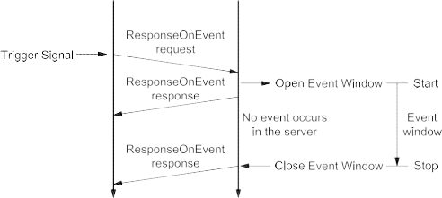
Figure 13 — Finite event window — No event during active event window


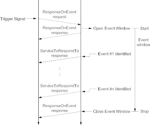
Figure 14 — Finite event window — Multiple events during active event window
9.10.5.3 Example #2 — ResponseOnEvent (infinite event window)
Table 108 — ResponseOnEvent request message flow example #2
|
Message direction:
|
client server
|
|
Message type:
|
Request
|
|
A_Data byte
|
Description (all values are in hexadecimal)
|
Byte value (hex)
|
Mnemonic
|
|
#1
|
ResponseOnEvent request SID
|
86
|
ROE
|
|
#2
|
eventTypeRecord [ eventType ] = onDTCStatusChange, storageState = doNotStoreEvent suppressPosRspMsgIndicationBit = FALSE
|
01
|
ET_ODTCSC
|
|
#3
|
eventWindowTime = infinite
|
02
|
EWT
|
|
#4
|
eventTypeRecord [ eventTypeParameter ] = testFailed status
|
01
|
ETP1
|
|
#5
|
serviceToRespondToRecord [ serviceId ] = ReadDTCInformation
|
19
|
RDTCI
|
|
#6
|
serviceToRespondToRecord [ sub-function ] =
|
01
|
RNDTC
|
| |
reportNumberOfDTCByStatusMask
|
|
|
|
#7
|
serviceToRespondToRecord [ DTCStatusMask ] = testFailed status
|
01
|
DTCSM
|
Table 109 — ResponseOnEvent initial positive response message flow example #2
|
Message direction:
|
server client
|
|
Message type:
|
Response
|
|
A_Data byte
|
Description (all values are in hexadecimal)
|
Byte value (hex)
|
Mnemonic
|
|
#1
|
ResponseOnEvent response SID
|
C6
|
ROEPR
|
|
#2
|
eventType = onDTCStatusChange
|
01
|
ET_ODTCSC
|
|
#3
|
numberOfIdentifiedEvents = 0
|
00
|
NOIE
|
|
#4
|
eventWindowTime = infinite
|
02
|
EWT
|
|
#5
|
eventTypeRecord [ eventTypeParameter ] = testFailed status
|
01
|
ETP1
|
|
#6
|
serviceToRespondToRecord [ serviceId ] = ReadDTCInformation
|
19
|
RDTCI
|
|
#7
|
serviceToRespondToRecord [ sub-function ] =
|
01
|
RNDTC
|
| |
reportNumberOfDTCByStatusMask
|
|
|
|
#8
|
serviceToRespondToRecord [ DTCStatusMask ] = testFailed status
|
01
|
DTCSM
|
Once the event logic is set up, it shall then be activated.
Table 110 — Start ResponseOnEvent request message flow example #2
|
Message direction:
|
client server
|
|
Message type:
|
Request
|
|
A_Data byte
|
Description (all values are in hexadecimal)
|
Byte value (hex)
|
Mnemonic
|
|
#1
|
ResponseOnEvent request SID
|
86
|
ROE
|
|
#2
|
eventTypeRecord [ eventType ] = startResponseOnEvent, storageState = doNotStoreEvent suppressPosRspMsgIndicationBit = FALSE
|
05
|
ET_STRTROE
|
|
#3
|
eventWindowTime (will not be evaluated)
|
02
|
EWT
|
Table 111 — ResponseOnEvent positive response message flow example #2
|
Message direction:
|
server client
|
|
Message type:
|
Response
|
|
A_Data byte
|
Description (all values are in hexadecimal)
|
Byte value (hex)
|
Mnemonic
|
|
#1
|
ResponseOnEvent response SID
|
C6
|
ROEPR
|
|
#2
|
eventType = onDTCStatusChange
|
05
|
ET_ODTCSC
|
|
#3
|
numberOfIdentifiedEvents = 0
|
00
|
NOIE
|
|
#4
|
eventWindowTime
|
02
|
EWT
|
In case the specified event occurs, the server sends the response message according to the specified serviceToRespondToRecord.
Table 112 — ReadDTCInformation positive response message flow example #1
|
Message direction:
|
server client
|
|
Message type:
|
Response
|
|
A_Data byte
|
Description (all values are in hexadecimal)
|
Byte value (hex)
|
Mnemonic
|
|
#1
|
ReadDTCInformation response SID
|
59
|
RDTCI
|
|
#2
|
DTCStatusAvailibilityMask
|
xx
|
DTCSAM
|
|
#3
#4
|
DTCCount [ DTCCountHighByte ] = 0
DTCCount [ DTCCountLowByte ] = 4
|
00
04
|
DTCCNT_HB
DTCCNT_LB
|
9.10.5.3.1 Example #2 — Flowcharts
The following flowcharts show two different kinds of server behaviour.
-
No event occurs within the infinite event window.
-
Multiple events (#1 to #n) within a infinite event window: each positive response of the serviceToRespondTo is related to an identified event (#1 to #n) and shall have the same service identifier (SId) but might have different content.


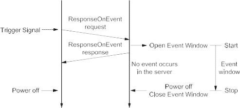
Figure 15 — Infinite event window — No event during active event window


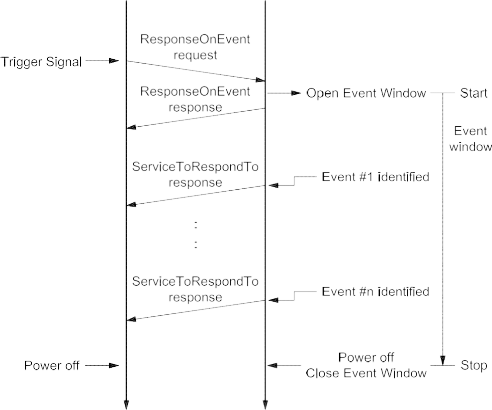
Figure 16 — Infinite event window — Multiple events during active event window
9.10.5.4 Example #3 — ResponseOnEvent (infinite event window) — Sub-function parameter “onComparisonOfValues”
This example only explains the utilization of sub-function parameter “onComparisonOfValues”, assuming that the communication behaviour of the ROE service described in Example #1 and Example #2 has not changed. Therefore, this example does not describe the complete message flow. Instead, only the event window set-up request message and the positive response message to the occurring event is shown and explained. Start and stop request messages as well as the different response messages are already described in the examples above.
The following conditions apply:
-
service 22 hex – ReadDataByIdentifier is chosen as the serviceToRespondTo;
-
the dataIdentifier 0104 hex includes the measurement value which is to be compared at data byte #11 and #12 (this measurement value may also be read by utilising service 22 hex);
-
an event occurs if the measurement value (MV) is higher than the so-called comparison parameter (CP), therefore the operator value (see description below) is chosen as 01 hex – “MV > CP”;
-
as hysteresis value 0A hex – 10 % is chosen;
-
as eventWindowTime the value 02 hex – “infinite” is chosen;
-
as storageState (eventType sub-function bit 6 ) the value 1 binary – “storeEvent” is chosen;
-
in any case, a response is requested.
The following is a description of the eventTypeRecord. The usage of the eventTypeRecord is vehicle- manufacturer-specific, similar to the eventTypes described so far. Therefore, the following description is only an example explaining the usage of the eventType “onComparisonOfValues”. The specific number of necessary eventTypeRecord parameters is also manufacturer-specific. In this example, 10 data bytes are used.
Byte #4&5: dataIdentifier 0104 hex.
Byte #6&7: Localization of reading and definition of reading type. The bit numbering within these 2 bytes of information is counted from the least significant bit through to the most significant bit. Bit #0 (LSB) - Bit #9 (MSB) contain the start bit number of the reading. With 10 bits, the maximal size of a data record is 128 bytes.
EXAMPLE 1 If the reading is in the 11th byte of the data record, the following applies: 11x8 = 88 dec = 0001011000b Bit
#10 - Bit #14: length in bits - 1. With 5 bits, there is a maximum size of 32 bits = “long”.
EXAMPLE 2 For a “word”, the length is therefore 15 dec = 01111b Bit #15: Sign entry: 1 = signed, 0 = unsigned.
EXAMPLE 3 Total assignment would be: 1011 1100 0101 1000b = BC58 hex, thus byte #6 contains BC hex, byte #7 contains 58 hex.
Byte #8: Comparison operation (operator) defines the type of comparison which shall be executed:
-
MV>CP content: 01 hex;
-
MVCP 02 hex;
-
MV=CP 03 hex;
-
MV>CP 04 hex;
-
“” provided for analogue values, “=” and “>” for digital variables;
-
MV: measurement value; and
-
CP: comparison parameter.
EXAMPLE 4 Operator MV > CP = 01 hex.
Byte #9-12: Comparison parameters: due to the 4-byte length, all data formats from Bit through to Long type can be transmitted.
EXAMPLE 5 If the comparison value is 5242 dec = 00 00 14 7A hex, byte #9 = 00 hex, byte #10 = 00 hex, byte #11 = 14 hex and byte #12 = 7A hex.
Byte #13: Hysteresis value (specified as a percentage of the comparison parameter): the value is specified directly. It only applies to the operators “”. In case of zero as the comparison value, the hysteresis value shall be defined as an absolute value.
EXAMPLE 6 Hysteresis value 10% = 0A hex.
Table 113 — ResponseOnEvent request message example #3
|
Message direction:
|
client server
|
|
Message type:
|
Request
|
|
A_Data byte
|
Description (all values are in hexadecimal)
|
Byte value (hex)
|
Mnemonic
|
|
#1
|
ResponseOnEvent request SID
|
86
|
ROE
|
|
#2
|
eventTypeRecord [ eventType ] = onComparisonOfValues, storageState = storeEvent suppressPosRspMsgIndicationBit=FALSE
|
47
|
ET_OCOV
|
|
#3
|
eventWindowTime = infinite
|
02
|
EWT
|
|
#4
#5
#6
#7
#8
#9
#10
#11
#12
#13
|
eventTypeRecord [ eventTypeParameter#1 ] = recordDataIdentifier High Byte eventTypeRecord [ eventTypeParameter#2 ] = recordDataIdentifier Low Byte eventTypeRecord [ eventTypeParameter#3 ] = Valueinfo #1 eventTypeRecord [ eventTypeParameter#4 ] = Valueinfo #2 eventTypeRecord [ eventTypeParameter#5 ] = Operator
eventTypeRecord [ eventTypeParameter#6 ] = Comparison Parameter Byte#4 eventTypeRecord [ eventTypeParameter#7 ] = Comparison Parameter Byte#3
eventTypeRecord [ eventTypeParameter#8 ] = Comparison Parameter Byte#2
eventTypeRecord [ eventTypeParameter#9 ] = Comparison Parameter Byte#1
eventTypeRecord [ eventTypeParameter#10 ] = Hysteresis [%]
|
01
04
BC 58
01
00
00
14
7A
0A
|
ETR_ETP1 ETR_ETP2 ETR_ETP3 ETR_ETP4 ETR_ETP5 ETR_ETP6 ETR_ETP7 ETR_ETP8
ETR_ETP9
ETR_ETP10
|
|
#14
#15
#16
|
serviceToRespondToRecord [ serviceID ] = ReadDataByIdentifier
serviceToRespondToRecord [ serviceParameter#1 ] = dataIdentifier (MSB) serviceToRespondToRecord [ serviceParameter#2 ] = dataIdentifier (LSB)
|
22
01
04
|
RDBI
DID_B1 DID_B2
|
NOTE Response message and subsequent initialisation sequence are not shown.
After a successful event window set-up and activation of the ROE mechanism, the server reacts if the measurement value is higher than 5242 decimal. The specified event occurs and the server sends the following message.
Table 114 — ReadDataByIdentifier positive response message example #3
|
Message direction:
|
server client
|
|
Message type:
|
Response
|
|
A_Data byte
|
Description (all values are in hexadecimal)
|
Byte value (hex)
|
Mnemonic
|
|
#1
|
ReadDataByIdentifier response SID
|
62
|
RDBIPR
|
|
#2
|
dataIdentifier [ byte#1 ] (MSB)
|
01
|
DID_B1
|
|
#3
|
dataIdentifier [ byte#2 ] (LSB)
|
04
|
DID_B2
|
|
#4
|
dataRecord [ data#1 ]
|
|
xx
|
DREC_DATA1
|
|
#5
|
dataRecord [ data#2 ]
|
|
xx
|
DREC_DATA2
|
|
#6
|
dataRecord [ data#3 ]
|
|
xx
|
DREC_DATA3
|
|
#7
|
dataRecord [ data#4 ]
|
|
xx
|
DREC_DATA4
|
|
#8
|
dataRecord [ data#5 ]
|
|
xx
|
DREC_DATA5
|
|
#9
|
dataRecord [ data#6 ]
|
|
xx
|
DREC_DATA6
|
|
#10
|
dataRecord [ data#7 ]
|
|
xx
|
DREC_DATA7
|
|
#11
|
dataRecord [ data#8 ]
|
|
xx
|
DREC_DATA8
|
|
#12
|
dataRecord [ data#9 ]
|
|
xx
|
DREC_DATA9
|
|
#13
|
dataRecord [ data#10 ]
|
|
xx
|
DREC_DATA10
|
|
#14
|
dataRecord [ data#11 ]
|
data content of byte#11: 14 hex
|
14
|
DREC_DATA11
|
|
#15
|
dataRecord [ data#12 ]
|
data content of byte#12: 7B hex
|
7B
|
DREC_DATA12
|
|
:
|
:
|
|
:
|
:
|
No further event occurs before the measurement value goes below 90 % of the comparison parameter value at least once. This behaviour is specified by the hysteresis value. If this condition was fulfilled and the measurement value is again higher than the comparison value, a new event occurs and a new ReadDataByIdentifier response message is sent by the server.
-
LinkControl (87 hex) service
-
Service description
The LinkControl service is used to control the communication link baud rate between the client and the server(s) for the exchange of diagnostic data. This service optionally applies to those data link layers which allow for a baud rate transition during an active diagnostic session.
NOTE Further details on the appliance and usage of this service on a certain data link layer can be found in the data- link-layer-specific diagnostic services implementation specification.
This service is used to transition the baud rate of the data link layer. To overcome functional communication, where the baud rate must be transitioned in multiple servers at the same time, the baud rate transition is split into two steps:
-
Step #1: The client verifies if the transition can be performed and informs the server(s) about the baud rate to be used. Each server shall respond positively (suppressPosRspMsgIndicationBit = FALSE) before the client performs step #2. This step does not actually perform the baud rate transition.
-
Step #2: The client actually requests the transition of the baud rate. This step shall only be performed if it is verified that the baud rate transition can be performed (step #1 performed). In case of functional communication, it is recommended that there should not be any response from a server when the baud rate is transitioned (suppressPosRspMsgIndicationBit = TRUE) because one server might already have been transitioned to the new baud rate while others still need to transmit their response message(s) (baud rate mismatch avoidance).
The linkControlType parameter in the request message, in conjunction with the conditional baudrateIdentifier/linkBaudrateRecord parameter, provides a mechanism to transition to a predefined or specifically defined baud rate.
Any baud rate transition shall occur as follows:
-
suppressPosRspMsgIndicationBit = TRUE: after the successful transmission/reception of the client
request message, which requests the baud rate transition.
-
suppressPosRspMsgIndicationBit = FALSE: after the successful transmission/reception of the server
positive response message, which confirms the successful reception of the request, which requests the baud rate transition.
NOTE This service is tied to a non-defaultSession. A session layer timer timeout will transition the server(s) back to its (their) normal speed of operation. The same applies if an ECUReset service (11 hex) is performed. The transition into another non-defaultSession shall not influence the baud rate.
IMPORTANT — The server and the client shall meet the request and response message behaviour as specified in 7.5.2 in the event that those addressing methods are implemented for this service.
-
Request message
-
Request message definition
Table 115 — Request message definition (linkControlType = verifyBaudrateTransitionWithFixedBaudrate)
|
A_Data byte
|
Parameter name
|
Cvt
|
Hex value
|
Mnemonic
|
|
#1
|
LinkControl Request Service Id
|
M
|
87
|
LC
|
|
#2
|
sub-function = [
linkControlType]
|
M
|
00-FF
|
LEV_ LCTP_
|
|
#3
|
baudrateIdentifier
|
Ca 1
|
00-FF
|
BI_
|
|
a The C1 parameter is present if the sub-function parameter indicates that a verification of a fixed baud rate (verifyBaudrateTransitionWithFixedBaudrate) is done.
|
Table 116 — Request message definition (linkControlType = verifyBaudrateTransitionWithSpecificBaudrate)
|
A_Data byte
|
Parameter name
|
Cvt
|
Hex value
|
Mnemonic
|
|
#1
|
LinkControl Request Service Id
|
M
|
87
|
LC
|
|
#2
|
sub-function = [
linkControlType]
|
M
|
00-FF
|
LEV_ LCTP_
|
|
#3
#4
#5
|
linkBaudrateRecord[] = [
baudrateHighByte baudrateMiddleByte baudrateLowByte ]
|
Ca 2
C2C2
|
00-FF
00-FF
00-FF
|
LBR_ BRHB BRMB BRLB
|
|
a The C2 parameter is present if the sub-function parameter indicates that a verification of a specific baud rate (verifyBaudrateTransitionWithSpecificBaudrate) is done.
|
-
Request message sub-function parameter $Level (LEV_) definition
The sub-function parameter linkControlType is used by the LinkControl request message to describe the action to be performed in the server [suppressPosRspMsgIndicationBit (bit 7) not shown in Table below].
Table 117 — Request message sub-function parameter definition
|
Hex (bit 6-0)
|
Description
|
Cvt
|
Mnemonic
|
|
00
|
ISOSAEReserved
This value is reserved by this document.
|
M
|
ISOSAERESRVD
|
|
01
|
verifyBaudrateTransitionWithFixedBaudrate
This parameter is used to verify if a transition to a predefined baud rate, which is specified by the baudrateIdentifier data parameter, can be performed.
|
U
|
VBTWFBR
|
|
02
|
verifyBaudrateTransitionWithSpecificBaudrate
This parameter is used to verify if a transition to a specifically defined baud rate, which is specified by the linkBaudrateRecord data parameter, can be performed.
|
U
|
VBTWSBR
|
|
03
|
transitionBaudrate
This sub-function parameter requests the server(s) to transition the baud rate to the one that was specified in the preceding verification message.
|
U
|
TB
|
|
04 - 3F
|
ISOSAEReserved
This range of values is reserved by this document for future definition.
|
M
|
ISOSAERESRVD
|
|
40 - 5F
|
vehicleManufacturerSpecific
This range of values is reserved for vehicle-manufacturer-specific use.
|
U
|
VMS
|
|
60 - 7E
|
systemSupplierSpecific
This range of values is reserved for system-supplier-specific use.
|
U
|
SSS
|
|
7F
|
ISOSAEReserved
This value is reserved by this document for future definition.
|
M
|
ISOSAERESRVD
|
-
Request message data parameter definition
The data parameters in Table 118 are defined for this service.
Table 118 — Request message data parameter definition
|
Definition
|
|
baudrateIdentifier
This conditional parameter references a fixed defined baud rate to transition to (see annex B.3).
|
|
linkBaudrateRecord
This conditional parameter record contains a specific baud rate ([bit/s]) in cases where the sub-function parameter indicates that a specific baud rate is used.
|
-
Positive response message
-
Positive response message definition
Table 119 — Positive response message definition
|
A_Data byte
|
Parameter name
|
Cvt
|
Hex value
|
Mnemonic
|
|
#1
|
LinkControl Response Service Id
|
S
|
C7
|
LCPR
|
|
#2
|
linkControlType
|
M
|
00-7F
|
LCTP
|
-
Positive response message data parameter definition
Table 120 — Response message data parameter definition
linkControlType
| Definition |
|
linkControlType
This parameter is an echo of bits 6 - 0 of the linkControlType sub-function parameter from the request message.
|
Definition
This parameter is an echo of bits 6 - 0 of the linkControlType sub-function parameter from the request message.
-
Supported negative response codes (NRC_)
The following negative response codes shall be implemented for this service. The circumstances under which each response code would occur are documented in Table 121.
Table 121 — Supported negative response codes
|
Hex
|
Description
|
Cvt
|
Mnemonic
|
|
12
|
subFunctionNotSupported
Send if the sub-function parameter in the request message is not supported.
|
M
|
SFNS
|
|
13
|
incorrectMessageLengthOrInvalidFormat
The length of the message is wrong.
|
M
|
IMLOIF
|
|
22
|
conditionsNotCorrect
This code shall be returned if the criteria for the requested LinkControl are not met.
|
M
|
CNC
|
|
24
|
requestSequenceError
This code shall be returned if the client requests the transition of the baud rate without a preceding verification step which specifies the baud rate to transition to.
|
M
|
RSE
|
|
31
|
requestOutOfRange
This code shall be returned if:
|
M
|
ROOR
|
-
the requested fixed baud rate (baudrateIdentifier) is invalid;
-
the specific baud rate (linkBaudrateRecord) is invalid.
-
Message flow example(s) LinkControl
-
Example #1 — Transition baud rate to fixed baud rate (PC baud rate 115200 kBit/s)
-
Step #1 — Verify if all criteria are met for a baud rate switch
Table 122 — LinkControl request message flow example #1 — step #1
|
Message direction:
|
client server
|
|
Message type:
|
Request
|
|
A_Data byte
|
Description (all values are in hexadecimal)
|
Byte value (hex)
|
Mnemonic
|
|
#1
|
LinkControl request SID
|
87
|
LC
|
|
#2
|
linkControlType = verifyBaudrateTransitionWithFixedBaudrate, suppressPosRspMsgIndicationBit = FALSE
|
01
|
VBTWFBR
|
|
#3
|
baudrateIdentifier = PC115200Baud
|
05
|
BI_PC115200
|
Table 123 — LinkControl positive response message flow example #1 — step #1
|
Message direction:
|
server client
|
|
Message type:
|
Response
|
|
A_Data byte
|
Description (all values are in hexadecimal)
|
Byte value (hex)
|
Mnemonic
|
|
#1
|
LinkControl response SID
|
C7
|
LCPR
|
|
#2
|
linkControlType = verifyBaudrateTransitionWithFixedBaudrate
|
01
|
VBTWFBR
|
-
Step #2: Transition the baud rate
Table 124 — LinkControl request message flow example #1 — step #2
|
Message direction:
|
client server
|
|
Message type:
|
Request
|
|
A_Data byte
|
Description (all values are in hexadecimal)
|
Byte value (hex)
|
Mnemonic
|
|
#1
|
LinkControl request SID
|
87
|
LC
|
|
#2
|
linkControlType = transitionBaudrate, suppressPosRspMsgIndicationBit = TRUE
|
83
|
TB
|
There is no response from the server(s). The client and the server(s) shall transition the baud rate of their communication link.
-
Example #2 — Transition baud rate to specific baud rate (150kBit/s)
-
Step #1 — Verify if all criteria are met for a baud rate switch
Table 125 — LinkControl request message flow example #2, step #1
|
Message direction:
|
client server
|
|
Message type:
|
Request
|
|
A_Data byte
|
Description (all values are in hexadecimal)
|
Byte value (hex)
|
Mnemonic
|
|
#1
|
LinkControl request SID
|
87
|
LC
|
|
#2
|
linkControlType = verifyBaudrateTransitionWithSpecificBaudrate, suppressPosRspMsgIndicationBit = FALSE
|
02
|
VBTWSBR
|
|
#3
|
linkBaudrateRecord [ baudrateHighByte ] (150kBit/s)
|
02
|
BR_BRHB
|
|
#4
|
linkBaudrateRecord [ baudrateMiddleByte ]
|
49
|
BR_BRMB
|
|
#5
|
linkBaudrateRecord [ baudrateLowByte ]
|
F0
|
BR_BRLB
|
Table 126 — LinkControl positive response message flow example #2, step #1
|
Message direction:
|
server client
|
|
Message type:
|
Response
|
|
A_Data byte
|
Description (all values are in hexadecimal)
|
Byte value (hex)
|
Mnemonic
|
|
#1
|
LinkControl response SID
|
C7
|
LCPR
|
|
#2
|
linkControlType = verifyBaudrateTransitionWithSpecificBaudrate
|
02
|
VBTWSBR
|
-
Step #2 — Transition the baud rate
Table 127 — LinkControl request message flow example #2, step #2
|
Message direction:
|
client server
|
|
Message type:
|
Request
|
|
A_Data byte
|
Description (all values are in hexadecimal)
|
Byte value (hex)
|
Mnemonic
|
|
#1
|
LinkControl request SID
|
87
|
LC
|
|
#2
|
linkControlType = transitionBaudrate, suppressPosRspMsgIndicationBit = TRUE
|
83
|
TB
|
There is no response from the server(s). The client and the server(s) shall transition the baud rate of their communication link.
-
Data transmission functional unit
-
Overview
Table 128 — Data transmission functional unit
|
Service
|
Description
|
|
ReadDataByIdentifier
|
The client requests to read the current value of a record identified by a provided dataIdentifier.
|
|
ReadMemoryByAddress
|
The client requests to read the current value of the provided memory range.
|
|
ReadScalingDataByIdentifier
|
The client requests to read the scaling information of a record identified by a provided dataIdentifier.
|
|
ReadDataByPeriodicIdentifier
|
The client requests to schedule data in the server for periodic transmission.
|
|
DynamicallyDefineDataIdentifier
|
The client requests to dynamically define data Identifiers that may subsequently be read by the readDataByIdentifier service.
|
|
WriteDataByIdentifier
|
The client requests to write a record specified by a provided dataIdentifier.
|
|
WriteMemoryByAddress
|
The client requests to overwrite a provided memory range.
|
-
ReadDataByIdentifier (22 hex) service
-
Service description
The ReadDataByIdentifier service allows the client to request data record values from the server identified by one or more dataIdentifiers.
The client request message contains one or more two-byte dataIdentifier values that identify data record(s) maintained by the server (refer to C.1 for allowed dataIdentifier values). The format and definition of the dataRecord shall be vehicle-manufacturer- or system-supplier-specific, and may include analogue input and output signals, digital input and output signals, internal data and system status information if supported by the server.
The server may limit the number of dataIdentifiers that can be simultaneously requested as agreed upon by the vehicle manufacturer and system supplier.
Upon receiving a ReadDataByIdentifier request, the server shall access the data elements of the records specified by the dataIdentifier parameter(s) and transmit their value in one single ReadDataByIdentifier positive response containing the associated dataRecord parameter(s). The request message may contain the same dataIdentifier multiple times. The server shall treat each dataIdentifier as a separate parameter and respond with data for each dataIdentifier as often as requested.
IMPORTANT — The server and the client shall meet the request and response message behaviour as specified in 7.5.3 in the event that those addressing methods are implemented for this service.
-
Request message
-
Request message definition
Table 129 — Request message definition
|
A_Data byte
|
Parameter name
|
Cvt
|
Hex value
|
Mnemonic
|
|
#1
|
ReadDataByIdentifier Request Service Id
|
M
|
22
|
RDBI
|
|
#2
#3
|
dataIdentifier[] #1 = [
byte#1 (MSB) byte#2 ]
|
M M
|
00-FF
00-FF
|
DID_ HB LB
|
|
:
|
:
|
:
|
:
|
:
|
|
#n-1
#n
|
dataIdentifier[] #m = [
byte#1 (MSB) byte#2 ]
|
U U
|
00-FF
00-FF
|
DID_ HB LB
|
-
Request message sub-function parameter $Level (LEV_) Definition
This service does not use a sub-function parameter.
-
Request message data parameter definition
The following data parameters are defined for this service.
Table 130 — Request message data parameter definition
dataIdentifier (#1 to #m)
| Definition |
|
dataIdentifier (#1 to #m)
This parameter identifies the server data record(s) being requested by the client (see C.1 for detailed parameterThis parameter identifies the server data record(s) being requested by the client (see C.1 for detailed parameterdefinition).
|
Definition
This parameter identifies the server data record(s) being requested by the client (see C.1 for detailed parameter definition).
-
Positive response message
-
Positive response message definition
Table 131 — Positive response message definition
|
A_Data byte
|
Parameter name
|
Cvt
|
Hex value
|
Mnemonic
|
|
#1
|
ReadDataByIdentifier Response Service Id
|
M
|
62
|
RDBIPR
|
|
#2
#3
|
dataIdentifi
|
er[] #1 = [
byte#1 (MSB) byte#2 ]
|
M M
|
00-FF
00-FF
|
DID_ HB LB
|
|
#4
:
#(k-1)+4
|
dataRecord[] #1 = [
data#1
:
data#k ]
|
M
: U
|
00-FF
: 00-FF
|
DREC_ DATA_1
:
DATA_m
|
|
:
|
:
|
:
|
:
|
:
|
|
#n-(o-1)-2
#n-(o-1)-1
|
dataIdentifier[] #m = [
byte#1 (MSB) byte#2 ]
|
U U
|
00-FF
00-FF
|
DID_ HB LB
|
|
#n-(o-1)
:
#n
|
dataRecord[] #m = [
data#1
:
data#o ]
|
U
: U
|
00-FF
: 00-FF
|
DREC_ DATA_1
:
DATA_k
|
-
Positive response message data parameter definition
Table 132 — Response message data parameter definition
|
Definition
|
|
dataIdentifier (#1 to #m)
This parameter is an echo of the data parameter dataIdentifier from the request message.
|
|
dataRecord (#1 to #k/o)
This parameter is used by the ReadDataByIdentifier positive response message to provide the requested data record values to the client. The content of the dataRecord is not defined in this document and is vehicle-manufacturer-specific.
|
-
Supported negative response codes (NRC_)
The following negative response codes shall be implemented for this service. The circumstances under which each response code would occur are documented in Table 133.
Table 133 — Supported negative response codes
|
Hex
|
Description
|
Cvt
|
Mnemonic
|
|
13
|
incorrectMessageLengthOrInvalidFormat
This response code shall be sent if the length of the request message is invalid.
|
M
|
IMLOIF
|
|
22
|
conditionsNotCorrect
This response code shall be sent if the operating conditions of the server for performing the required action are not met.
|
U
|
CNC
|
|
31
|
requestOutOfRange
This code shall be sent if:
|
M
|
ROOR
|
|
33
|
securityAccessDenied
This code shall be sent if at least one of the dataIdentifiers is secured and the server is not in an unlocked state.
|
M
|
SAD
|
-
none of the requested dataIdentifier values are supported by the device;
-
the client exceeded the maximum number of dataIdentifiers allowed to be requested at a time.
-
Message flow example ReadDataByIdentifier
-
Assumptions
This subclause specifies the conditions to be fulfilled for the example in order to perform a ReadDataByIdentifier service. The client may request dataIdentifier data at any time independent of the status of the server.
The dataIdentifier examples below are specific to a powertrain device (e.g. engine control module). Refer to ISO/TR 15031-2 for further details regarding accepted terms/definitions/acronyms for emissions-related systems.
The first example reads a single two-byte dataIdentifier containing a single piece of information (where dataIdentifier F190 hex contains the VIN number).
The second example demonstrates requesting multiple dataIdentifiers with a single request (where dataIdentifier 010A hex contains engine coolant temperature, throttle position, engine speed, manifold absolute pressure, mass air flow, vehicle speed sensor, barometric pressure, calculated load value, idle air control and accelerator pedal position, and dataIdentifier 0110 hex contains battery positive voltage).
-
Example #1 — Read single dataIdentifier F190 hex (VIN number)
Table 134 — ReadDataByIdentifier request message flow example #1
|
Message direction:
|
client server
|
|
Message type:
|
Request
|
|
A_Data byte
|
Description (all values are in hexadecimal)
|
Byte value (hex)
|
Mnemonic
|
|
#1
|
ReadDataByIdentifier request SID
|
22
|
RDBI
|
|
#2
#3
|
dataIdentifier [ byte#1 ] (MSB)
dataIdentifier [ byte#2 ]
|
F1
90
|
DID_B1
DID_B2
|
Table 135 — ReadDataByIdentifier positive response message flow example #1
|
Message direction:
|
server client
|
|
Message type:
|
Response
|
|
A_Data byte
|
Description (all values are in hexadecimal)
|
Byte value (hex)
|
Mnemonic
|
|
#1
|
ReadDataByIdentifier response SID
|
62
|
RDBIPR
|
|
#2
|
dataIdentifier [ byte#1 ] (MSB)
|
F1
|
DID_B1
|
|
#3
|
dataIdentifier [ byte#2 ]
|
90
|
DID_B2
|
|
#4
|
dataRecord [ data#1 ]
|
= VIN Digit 1
|
= “W”
|
57
|
DREC_DATA1
|
|
#5
|
dataRecord [ data#2 ]
|
= VIN Digit 2
|
= “0”
|
30
|
DREC_DATA2
|
|
#6
|
dataRecord [ data#3 ]
|
= VIN Digit 3
|
= “L”
|
4C
|
DREC_DATA3
|
|
#7
|
dataRecord [ data#4 ]
|
= VIN Digit 4
|
= “0”
|
30
|
DREC_DATA4
|
|
#8
|
dataRecord [ data#5 ]
|
= VIN Digit 5
|
= “0”
|
30
|
DREC_DATA5
|
|
#9
|
dataRecord [ data#6 ]
|
= VIN Digit 6
|
= “0”
|
30
|
DREC_DATA6
|
|
#10
|
dataRecord [ data#7 ]
|
= VIN Digit 7
|
= “0”
|
30
|
DREC_DATA7
|
|
#11
|
dataRecord [ data#8 ]
|
= VIN Digit 8
|
= “4”
|
34
|
DREC_DATA8
|
|
#12
|
dataRecord [ data#9 ]
|
= VIN Digit 9
|
= “3”
|
33
|
DREC_DATA9
|
|
#13
|
dataRecord [ data#10 ]
|
= VIN Digit 10
|
= “M”
|
4D
|
DREC_DATA10
|
|
#14
|
dataRecord [ data#11 ]
|
= VIN Digit 11
|
= “B”
|
42
|
DREC_DATA11
|
|
#15
|
dataRecord [ data#12 ]
|
= VIN Digit 12
|
= “5”
|
35
|
DREC_DATA12
|
|
#16
|
dataRecord [ data#13 ]
|
= VIN Digit 13
|
= “4”
|
34
|
DREC_DATA13
|
|
#17
|
dataRecord [ data#14 ]
|
= VIN Digit 14
|
= “1”
|
31
|
DREC_DATA14
|
|
#18
|
dataRecord [ data#15 ]
|
= VIN Digit 15
|
= “3”
|
33
|
DREC_DATA15
|
|
#19
|
dataRecord [ data#16 ]
|
= VIN Digit 16
|
= “2”
|
32
|
DREC_DATA16
|
|
#20
|
dataRecord [ data#17 ]
|
= VIN Digit 17
|
= “6”
|
36
|
DREC_DATA17
|
-
Example #2 — Read multiple dataIdentifiers 010A hex and 0110 hex
Table 136 — ReadDataByIdentifier request message flow example #2
|
Message direction:
|
client server
|
|
Message type:
|
Request
|
|
A_Data byte
|
Description (all values are in hexadecimal)
|
Byte value (hex)
|
Mnemonic
|
|
#1
|
ReadDataByIdentifier request SID
|
22
|
RDBI
|
|
#2
#3
|
dataIdentifier #1 [ byte#1 ] (MSB)
dataIdentifier #1 [ byte#2 ]
|
01
0A
|
DID_B1
DID_B2
|
|
#4
#5
|
dataIdentifier #2 [ byte#1 ] (MSB)
dataIdentifier #2 [ byte#2 ]
|
01
10
|
DID_B1
DID_B2
|
Table 137 — ReadDataByIdentifier positive response message flow example #2
|
Message direction:
|
server client
|
|
Message type:
|
Response
|
|
A_Data byte
|
Description (all values are in hexadecimal)
|
Byte value (hex)
|
Mnemonic
|
|
#1
|
ReadDataByIdentifier response SID
|
62
|
RDBIPR
|
|
#2
|
dataIdentifier [ byte#1 ] (MSB)
|
01
|
DID_B1
|
|
#3
|
dataIdentifier [ byte#2 ] (LSB)
|
0A
|
DID_B2
|
|
#4
|
dataRecord [data#1 ]
|
= ECT
|
A6
|
DREC_DATA1
|
|
#5
|
dataRecord [data#2 ]
|
= TP
|
66
|
DREC_DATA2
|
|
#6
|
dataRecord [data#3 ]
|
= RPM
|
07
|
DREC_DATA3
|
|
#7
|
dataRecord [data#4 ]
|
= RPM
|
50
|
DREC_DATA4
|
|
#8
|
dataRecord [data#5 ]
|
= MAP
|
20
|
DREC_DATA5
|
|
#9
|
dataRecord [data#6 ]
|
= MAF
|
1A
|
DREC_DATA6
|
|
#10
|
dataRecord [data#7 ]
|
= VSS
|
00
|
DREC_DATA7
|
|
#11
|
dataRecord [data#8 ]
|
= BARO
|
63
|
DREC_DATA8
|
|
#12
|
dataRecord [data#9 ]
|
= LOAD
|
4A
|
DREC_DATA9
|
|
#13
|
dataRecord [data#10 ]
|
= IAC
|
82
|
DREC_DATA10
|
|
#14
|
dataRecord [data#11 ]
|
= APP
|
7E
|
DREC_DATA11
|
|
#15
|
dataIdentifier [ byte#1 ] (MSB)
|
01
|
DID_B1
|
|
#16
|
dataIdentifier [ byte#2 ] (LSB)
|
10
|
DID_B2
|
|
#17
|
dataRecord [ data#1 ] = B+
|
8C
|
DREC_DATA1
|
-
ReadMemoryByAddress (23 hex) service
-
Service description
The ReadMemoryByAddress service allows the client to request memory data from the server via a provided starting address and to specify the size of memory to be read.
The ReadMemoryByAddress request message is used to request memory data from the server identified by the parameter memoryAddress and memorySize. The number of bytes used for the memoryAddress and memorySize parameter is defined by addressAndLengthFormatIdentifier (low and high nibble).
It is also possible to use a fixed addressAndLengthFormatIdentifier and unused bytes within the memoryAddress or memorySize parameter are padded with the value 00 hex in the higher range address locations.
In case of overlapping memory areas, it is possible to use an additional memoryAddress byte as a memoryIdentifier (e.g. use of internal and external flash).
The server sends data record values via the ReadMemoryByAddress positive response message. The format and definition of the dataRecord parameter shall be vehicle manufacturer specific. The dataRecord parameter may include analogue input and output signals, digital input and output signals, internal data and system status information if supported by the server.
IMPORTANT — The server and the client shall meet the request and response message behaviour as specified in 7.5.3 in the event that those addressing methods are implemented for this service.
-
Request message
-
Request message definition
Table 138 — Request message definition
|
A_Data byte
|
Parameter name
|
Cvt
|
Hex value
|
Mnemonic
|
|
#1
|
ReadMemoryByAddress Request Service Id
|
M
|
23
|
RMBA
|
|
#2
|
addressAndLengthFormatIdentifier
|
M
|
00-FF
|
ALFID
|
|
#3
|
memoryAddress[] = [
byte#1 (MSB)
:
byte#m ]
|
M
|
00-FF
|
MA_
|
|
B1
|
|
:
|
:
|
:
|
:
|
|
#(m-1)+3
|
Ca 1
|
00-FF
|
Bm
|
|
#n-(k-1)
|
memorySize[] = [
byte#1 (MSB)
:
byte#k ]
|
M
|
00-FF
|
MS_
|
|
B1
|
|
:
|
:
|
:
|
:
|
|
#n
|
Cb 2
|
00-FF
|
Bk
|
| |
-
The presence of the C1parameter depends on address length information parameter of the addressAndLengthFormatIdentifier.
-
The presence of the C2parameter depends on the memory size length information of the addressAndLengthFormatIdentifier.
-
Request message sub-function parameter $Level (LEV_) definition
This service does not use a sub-function parameter.
-
Request message data parameter definition
The following data parameters are defined for this service.
Table 139 — Request message data parameter definition
|
Definition
|
|
addressAndLengthFormatIdentifier
This parameter is a one byte value with each nibble encoded separately (see annex G.1 for example values): bit 7 - 4: length (number of bytes) of the memorySize parameter;
bit 3 - 0: length (number of bytes) of the memoryAddress parameter.
|
|
memoryAddress
The parameter memoryAddress is the starting address of server memory from which data is to be retrieved. The number of bytes used for this address is defined by the low nibble (bit 3 - 0) of the addressFormatIdentifier. Byte#m in the memoryAddress parameter is always the least significant byte of the address being referenced in the server. The most significant byte of the address can be used as a memoryIdentifier.
An example of the use of a memoryIdentifier would be a dual processor server with 16-bit addressing and memory address overlap (when a given address is valid for either processor but yields a different physical memory device or internal and external flash is used). In this case, an otherwise unused byte within the memoryAddress parameter can be specified as a memoryIdentifier used to select the desired memory device. Usage of this functionality shall be as defined by vehicle manufacturer/system supplier.
|
|
memorySize
The parameter memorySize in the ReadMemoryByAddress request message specifies the number of bytes to be read starting at the address specified by memoryAddress in the server's memory. The number of bytes used for this size is defined by the high nibble (bit 7 - 4) of the addressFormatIdentifier.
|
-
Positive response message
-
Positive response message definition
Table 140 — Positive response message definition
|
A_Data byte
|
Parameter name
|
Cvt
|
Hex value
|
Mnemonic
|
|
#1
|
ReadMemoryByAddress Response Service Id
|
M
|
63
|
RMBAPR
|
|
#2
:
#n
|
dataRecord[] = [
data#1
:
data#m ]
|
M
: U
|
00-FF
: 00-FF
|
DREC_ DATA_1
:
DATA_m
|
-
Positive response message data parameter definition
Table 141 — Response message data parameter definition
dataRecord
| Definition |
|
dataRecord
This parameter is used by the ReadMemoryByAddress positive response message to provide the requested data recordThis parameter is used by the ReadMemoryByAddress positive response message to provide the requested data recordvalues to the client. The content of the dataRecord is not defined in this document and shall reflect the requested memorycontents. Data formatting shall be as defined by vehicle manufacturer/system supplier.
|
Definition
This parameter is used by the ReadMemoryByAddress positive response message to provide the requested data record values to the client. The content of the dataRecord is not defined in this document and shall reflect the requested memory contents. Data formatting shall be as defined by vehicle manufacturer/system supplier.
-
Supported negative response codes (NRC_)
The following negative response codes shall be implemented for this service. The circumstances under which each response code would occur are documented in Table 142.
Table 142 — Supported negative response codes
|
Hex
|
Description
|
Cvt
|
Mnemonic
|
|
13
|
incorrectMessageLengthOrInvalidFormat
The length of the message is wrong.
|
M
|
IMLOIF
|
|
22
|
conditionsNotCorrect
This response code shall be sent if the operating conditions of the server are not met to perform the required action.
|
U
|
CNC
|
|
31
|
requestOutOfRange
This response code shall be sent if
|
M
|
ROOR
|
|
33
|
SecurityAccessDenied
This code shall be sent if any memory address within the interval [$MA, ($MA + $MS
-$1)] is secure and the server is locked.
|
M
|
SAD
|
-
any memory address within the interval [$MA, ($MA + $MS -$1)] is invalid,
-
any memory address within the interval [$MA, ($MA + $MS -$1)] is restricted,
-
the memorySize parameter value in the request message is greater than the maximum value supported by the server,
-
the specified addressAndLengthFormatIdentifier is not valid.
-
Message flow example ReadMemoryByAddress
-
Assumptions
This subclause specifies the conditions to be fulfilled for the example to perform a ReadMemoryByAddress service. The service in this example is not limited by any restriction of the server.
-
Example #1 — ReadMemoryByAddress — 4-byte (32-bit) addressing
The client reads 259 data bytes from the server’s memory starting at memory address 20481392 hex.
Table 143 — ReadMemoryByAddress request message flow example #1
|
Message direction:
|
client server
|
|
Message type:
|
Request
|
|
A_Data byte
|
Description (all values are in hexadecimal)
|
Byte value (hex)
|
Mnemonic
|
|
#1
|
ReadMemoryByAddress request SID
|
23
|
RMBA
|
|
#2
|
addressAndLengthFormatIdentifier
|
24
|
ALFID
|
|
#3
|
memoryAddress [ byte#1 ] (MSB)
|
20
|
MA_B1
|
|
#4
|
memoryAddress [ byte#2 ]
|
48
|
MA_B2
|
|
#5
|
memoryAddress [ byte#3 ]
|
13
|
MA_B3
|
|
#6
|
memoryAddress [ byte#4 ]
|
92
|
MA_B4
|
|
#7
|
memorySize [ byte#1 ] (MSB)
|
01
|
MS_B1
|
|
#8
|
memorySize [ byte#2 ]
|
03
|
MS_B2
|
Table 144 — ReadMemoryByAddress positive response message flow example #1
|
Message direction:
|
server client
|
|
Message type:
|
Response
|
|
A_Data byte
|
Description (all values are in hexadecimal)
|
Byte value (hex)
|
Mnemonic
|
|
#1
|
ReadMemoryByAddress response SID
|
63
|
RMBAPR
|
|
#2
|
dataRecord [ data#1 ] (memory cell #1)
|
00
|
DREC_DATA_1
|
|
:
|
:
|
:
|
:
|
|
#259+1
|
dataRecord [ data#3 ] (memory cell #259)
|
8C
|
DREC_DATA_259
|
-
Example #2 — ReadMemoryByAddress — 2-byte (16-bit) addressing
The client reads five data bytes from the server’s memory starting at memory address 4813 hex.
Table 145 — ReadMemoryByAddress request message flow example #2
|
Message direction:
|
client server
|
|
Message type:
|
Request
|
|
A_Data byte
|
Description (all values are in hexadecimal)
|
Byte value (hex)
|
Mnemonic
|
|
#1
|
ReadMemoryByAddress request SID
|
23
|
RMBA
|
|
#2
|
addressAndLengthFormatIdentifier
|
12
|
ALFID
|
|
#3
#4
|
memoryAddress [ byte#1 ] (MSB)
memoryAddress [ byte#2 ] (LSB)
|
48
13
|
MA_B1
MA_B2
|
|
#5
|
memorySize [ byte#1 ]
|
05
|
MS_B1
|
Table 146 — ReadMemoryByAddress positive response message flow example #2
|
Message direction:
|
server client
|
|
Message type:
|
Response
|
|
A_Data byte
|
Description (all values are in hexadecimal)
|
Byte value (hex)
|
Mnemonic
|
|
#1
|
ReadMemoryByAddress response SID
|
63
|
RMBAPR
|
|
#2
|
dataRecord [ data#1 ] (memory cell #1)
|
43
|
DREC_DATA_1
|
|
#3
|
dataRecord [ data#2 ] (memory cell #2)
|
2A
|
DREC_DATA_2
|
|
#4
|
dataRecord [ data#3 ] (memory cell #3)
|
07
|
DREC_DATA_3
|
|
#5
|
dataRecord [ data#4 ] (memory cell #4)
|
2A
|
DREC_DATA_4
|
|
#6
|
dataRecord [ data#5 ] (memory cell #5)
|
55
|
DREC_DATA_5
|
-
Example #3 — ReadMemoryByAddress — 3-byte (24-bit) addressing
The client reads three data bytes from the server's external RAM cells starting at memory address 204813 hex.
Table 147 — ReadMemoryByAddress request message flow example #3
|
Message direction:
|
client server
|
|
Message type:
|
Request
|
|
A_Data byte
|
Description (all values are in hexadecimal)
|
Byte value (hex)
|
Mnemonic
|
|
#1
|
ReadMemoryByAddress request SID
|
23
|
RMBA
|
|
#2
|
addressAndLengthFormatIdentifier
|
23
|
ALFID
|
|
#3
|
memoryAddress [ byte#1 ] (MSB)
|
20
|
MA_B1
|
|
#4
|
memoryAddress [ byte#2 ]
|
48
|
MA_B2
|
|
#5
|
memoryAddress [ byte#3 ] (LSB)
|
13
|
MA_B3
|
|
#6
|
memorySize [ byte#1 ] (MSB)
|
00
|
MS_B1
|
|
#7
|
memorySize [ byte#2 ] (LSB)
|
03
|
MS_B2
|
Table 148 — ReadMemoryByAddress first positive response message, example #3
|
Message direction:
|
server client
|
|
Message type:
|
Response
|
|
A_Data byte
|
Description (all values are in hexadecimal)
|
Byte value (hex)
|
Mnemonic
|
|
#1
|
ReadMemoryByAddress response SID
|
63
|
RMBAPR
|
|
#2
|
dataRecord [ data#1 ] (memory cell #1)
|
00
|
DREC_DATA_1
|
|
#3
|
dataRecord [ data#2 ] (memory cell #2)
|
01
|
DREC_DATA_2
|
|
#4
|
dataRecord [ data#3 ] (memory cell #3)
|
8C
|
DREC_DATA_3
|
-
ReadScalingDataByIdentifier (24 hex) service
-
Service description
The ReadScalingDataByIdentifier service allows the client to request scaling data record information from the server identified by a dataIdentifier.
The client request message contains one dataIdentifier value that identifies data record(s) maintained by the server (refer to C.1 for allowed dataIdentifier values). The format and definition of the dataRecord shall be vehicle-manufacturer-specific and may include analogue input and output signals, digital input and output signals, internal data and system status information if supported by the server.
Upon receiving a ReadScalingDataByIdentifier request, the server shall access the scaling information associated with the specified dataIdentifier parameter and transmit the scaling information values in one ReadScalingDataByIdentifier positive response.
IMPORTANT — The server and the client shall meet the request and response message behaviour as specified in 7.5.3 in the event that those addressing methods are implemented for this service.
-
Request message
-
Request message definition
Table 149 — Request message definition
|
A_Data byte
|
Parameter name
|
Cvt
|
Hex value
|
Mnemonic
|
|
#1
|
ReadScalingDataByIdentifier Request Service Id
|
M
|
24
|
RSDBI
|
|
#2
#3
|
dataIdentifier[] = [
byte#1 (MSB) byte#2 ]
|
M M
|
00-FF
00-FF
|
DID_ HB LB
|
-
Request message sub-function parameter $Level (LEV_) definition
This service does not use a sub-function parameter.
-
Request message data parameter definition
The following data parameters are defined for this service.
Table 150 — Request message data parameter definition
dataIdentifier
|
Definition
dataIdentifier
This parameter identifies the server data record that is being requested by the client (see C.1 for a detailed parameterdefinition).
|
Definition
This parameter identifies the server data record that is being requested by the client (see C.1 for a detailed parameter definition).
-
Positive response message
-
Positive response message definition
Table 151 — Positive response message definition
|
A_Data byte
|
Parameter name
|
Cvt
|
Hex value
|
Mnemonic
|
|
#1
|
ReadScalingDataByIdentifier Response Service Id
|
M
|
64
|
RSDBIPR
|
|
#2
|
dataIdentifi
|
er[] = [
byte#1 (MSB) byte#2 (LSB) ]
|
M
|
00-FF
|
DID_
|
|
HB
|
|
#3
|
M
|
00-FF
|
LB
|
|
#4
|
scalingByte #1
|
M
|
00-FF
|
SB_1
|
|
#5
|
scalingByteExtension [] #1 = [
scalingByteExtensionParameter#1
:
scalingByteExtensionParameter#p ]
|
Ca 1
|
00-FF
|
SBE_
|
|
PAR1
|
|
:
|
:
|
:
|
:
|
|
#(p-1)+5
|
C1
|
00-FF
|
PARp
|
|
:
|
:
|
:
|
:
|
:
|
|
#n-r
|
scalingByte #k
|
Cb 2
|
00-FF
|
SB_k
|
|
#n-(r-1)
|
scalingByteExtension [] #k = [
scalingByteExtensionParameter#1
:
scalingByteExtensionParameter#r ]
|
C1
|
00-FF
|
SBE_
|
|
PAR1
|
|
:
|
:
|
:
|
:
|
|
#n
|
C1
|
00-FF
|
PARr
|
| |
-
The presence of the C1 parameter depends on the scalingByte high nibble. It is mandatory that it be present if the scalingByte high nibble is encoded as formula, unit/format or bitMappedReportedWithOutMask.
-
The presence of the C2parameter depends on whether the encoding of the scaling information requires more than one byte.
-
Positive response message data parameter definition
Table 152 — Response message data parameter definition
|
Definition
|
|
dataIdentifier
This parameter is an echo of the data parameter dataIdentifier from the request message.
|
|
scalingByte (#1 to #k)
This parameter is used by the ReadScalingDataByIdentifier positive response message to provide the requested scaling data record values to the client (see C.2 for a detailed parameter definition).
|
|
scalingByteExtension (#1 to #p / #1 to #r)
This parameter is used to provide additional information for scalingBytes with a high nibble encoded as formula, unit/format or bitMappedReportedWithOutMask (see C.3 for a detailed parameter definition).
|
-
Supported negative response codes (NRC_)
The following negative response codes shall be implemented for this service. The circumstances under which each response code would occur are documented in Table 153.
Table 153 — Supported negative response codes
|
Hex
|
Description
|
Cvt
|
Mnemonic
|
|
13
|
incorrectMessageLengthOrInvalidFormat
This response code shall be sent if the length of the request message is invalid.
|
M
|
IMLOIF
|
|
22
|
conditionsNotCorrect
This response code shall be sent if the operating conditions of the server to perform the required action are not met.
|
U
|
CNC
|
|
31
|
requestOutOfRange
This return code shall be sent if
|
M
|
ROOR
|
|
33
|
securityAccessDenied
This code shall be sent if the dataIdentifier is secured and the server is not in an unlocked state.
|
M
|
SAD
|
-
the requested dataIdentifier value is not supported by the device (physical addressing only),
-
the requested dataIdentifier value is supported by the device, but no scaling information is available for the specified dataIdentifier.
-
Message flow example ReadScalingDataByIdentifier
-
Assumptions
This subclause specifies the conditions to be fulfilled for the example to perform a ReadScalingDataByIdentifier service. The client may request dataIdentifier scaling data at any time, independent of the status of the server.
The first example reads the scaling information associated with the two (2) byte dataIdentifier F190 hex, which contains a single piece of information (17-character VIN number).
The second example demonstrates the use of a formula and unit identifier for specifying a data variable in a server.
The third example illustrates the use of readScalingDataByIdentifier to return the supported bits (validity mask) for a bit-mapped dataIdentifier that is reported without the mask through the use of readDataByIdenditfier.
|
Message direction:
|
client server
|
|
Message type:
|
Request
|
|
A_Data byte
|
Description (all values are in hexadecimal)
|
Byte value (hex)
|
Mnemonic
|
|
#1
|
ReadScalingDataByIdentifier request SID
|
24
|
RSDBI
|
|
#2
#3
|
dataIdentifier [ byte#1 ] (MSB)
dataIdentifier [ byte#2 ] (LSB)
|
F1
90
|
DID_B1
DID_B2
|
-
Example #1 — readScalingDataByIdentifier with dataIdentifier F190 hex (VIN number) Table 154 — ReadScalingDataByIdentifier request message flow example #1
Table 155 — ReadScalingDataByIdentifier positive response message flow example #1
|
Message direction:
|
server client
|
|
Message type:
|
Response
|
|
A_Data byte
|
Description (all values are in hexadecimal)
|
Byte value (hex)
|
Mnemonic
|
|
#1
|
ReadScalingDataByIdentifier response SID
|
64
|
RSDBIPR
|
|
#2
#3
|
dataIdentifier [ byte#1 ] (MSB)
dataIdentifier [ byte#2 ] (LSB)
|
F1
90
|
DID_B1
DID_B2
|
|
#4
|
scalingByte#1 {ASCII, 15 data bytes}
|
6F
|
SB_1
|
|
#5
|
scalingByte#2 {ASCII, 2 data bytes}
|
62
|
SB_2
|
|
Message direction:
|
client server
|
|
Message type:
|
Request
|
|
A_Data byte
|
Description (all values are in hexadecimal)
|
Byte value (hex)
|
Mnemonic
|
|
#1
|
ReadScalingDataByIdentifier request SID
|
24
|
RSDBI
|
|
#2
#3
|
dataIdentifier [ byte#1 ] (MSB)
dataIdentifier [ byte#2 ] (LSB)
|
01
05
|
DID_B1
DID_B2
|
-
Example #2 — readScalingDataByIdentifier with dataIdentifier 0105 hex (Vehicle Speed) Table 156 — ReadScalingDataByIdentifier request message flow example #2
Table 157 — ReadScalingDataByIdentifier positive response message flow example #2
|
Message direction:
|
server client
|
|
Message type:
|
Response
|
|
A_Data byte
|
Description (all values are in hexadecimal)
|
Byte value (hex)
|
Mnemonic
|
|
#1
|
ReadScalingDataByIdentifier response SID
|
64
|
RSDBIPR
|
|
#2
|
dataIdentifier [ byte#1 ] (MSB)
|
01
|
DID_B1
|
|
#3
|
dataIdentifier [ byte#2 ] (LSB)
|
05
|
DID_B2
|
|
#4
|
scalingByte #1 {unsigned numeric, 1 data byte}
|
01
|
SBYT_1
|
|
#5
|
scalingByte #2 {formula, 0 data bytes}
|
90
|
SB_2
|
|
#6
|
scalingByteExtension #2 [ byte#1 ] {formulaIdentifier = C0 * x + C1}
|
00
|
SBE_21
|
|
#7
|
scalingByteExtension #2 [ byte#2 ] {C0 high byte}
|
E0
|
SBE_22
|
|
#8
|
scalingByteExtension #2 [ byte#3 ] {C0 low byte} [ C0 = 75 * 102 ]
|
4B
|
SBE_23
|
|
#9
|
scalingByteExtension #2 [ byte#4 ] {C1 high byte}
|
00
|
SBE_24
|
|
#10
|
scalingByteExtension #2 [ byte#5 ] {C1 low byte} [ C1 = 30 * 100]
|
1E
|
SBE_25
|
|
#11
|
scalingByte#3 {unit/format, 0 data bytes}
|
A0
|
SB_3
|
|
#12
|
scalingByteExtension #3 [ byte#1 ] {unit ID, km/h}
|
30
|
SBE_31
|
Using the information contained in C.2 for decoding the scalingBytes, constants (C0, C1) and units, the data variable of vehicle speed is calculated using the following formula:
Vehicle Speed = (0.75 * x + 30) km/h
where x is the actual data stored in the server and is identified by dataIdentifier 0105 hex.
-
Example #3 — readScalingDataByIdentifier with dataIdentifier 0967 hex
This example shows how a client could determine which bits are supported for a dataIdentifier in a server that is formatted as a bit-mapped record reported without a validity mask.
The example dataIdentifier (0967 hex) is defined in Table 158.
Table 158 — Example data definition
|
Data Byte
|
Bit(s)
|
Description
|
|
#1
|
7-4
|
Unused.
|
|
3
|
Medium-speed fan is commanded on.
|
|
2
|
Medium-speed fan output fault detected.
|
|
1
|
Purge monitor soak time status flag.
|
|
0
|
Purge monitor idle test is prevented due to refuel event.
|
|
#2
|
7
|
Check fuel cap light is commanded on.
|
|
6
|
Check fuel cap light output fault detected.
|
|
5
|
Fan control A output fault detected.
|
|
4
|
Fan control B output fault detected.
|
|
3
|
High-speed fan output fault detected.
|
|
2
|
High-speed fan output is commanded on.
|
|
1
|
Purge monitor idle test (small leak) ready to run.
|
|
0
|
Purge monitor small leak has been monitored.
|
Table 159 — ReadScalingDataByIdentifier request message flow example #3
|
Message direction:
|
client server
|
|
Message type:
|
Request
|
|
A_Data byte
|
Description (all values are in hexadecimal)
|
Byte value (hex)
|
Mnemonic
|
|
#1
|
ReadScalingDataByIdentifier request SID
|
24
|
RSDBI
|
|
#2
#3
|
dataIdentifier [ byte#1 ] (MSB)
dataIdentifier [ byte#2 ] (LSB)
|
09
67
|
DID_B1
DID_B2
|
Table 160 — ReadScalingDataByIdentifier positive response message flow example #3
|
Message direction:
|
server client
|
|
Message type:
|
Response
|
|
A_Data byte
|
Description (all values are in hexadecimal)
|
Byte value (hex)
|
Mnemonic
|
|
#1
|
ReadScalingDataByIdentifier response SID
|
64
|
RSDBIPR
|
|
#2
#3
|
dataIdentifier [ byte#1 ] (MSB)
dataIdentifier [ byte#2 ] (LSB)
|
09
67
|
DID_HB
DID_LB
|
|
#4
|
scalingByte #1 {bitMappedReportedWithOutMask, 2 data bytes}
|
22
|
SBYT_1
|
|
#5
#6
|
scalingByteExtension #1 [ byte#1 ] {dataRecord#1 Validity Mask}
scalingByteExtension #1 [ byte#2 ] {dataRecord#2 Validity Mask}
|
03
43
|
SBYE_11
SBYE_12
|
The above example makes the assumption that the only bits supported (i.e. that contain information) for this dataIdentifier in the server are byte#1, bits 1 and 0, and byte#2, bits 6, 1, and 0.
-
ReadDataByPeriodicIdentifier (2A hex) service
-
Service description
The ReadDataByPeriodicIdentifier service allows the client to request the periodic transmission of data record values from the server identified by one or more periodicDataIdentifiers.
The client request message contains one or more 1-byte periodicDataIdentifier values that identify data record(s) maintained by the server. The periodicDataIdentifier represents the low byte of a dataIdentifier out of the dataIdentifier range reserved for this service (F2xx hex, refer to C.1 for allowed periodicDataIdentifier values), e.g. the periodicDataIdentifier E3 hex used in this service is the dataIdentifier F2E3 hex.
The format and definition of the dataRecord shall be vehicle-manufacturer-specific and may include analogue input and output signals, digital input and output signals, internal data and system status information if supported by the server.
Upon receiving a ReadDataByPeriodicIdentifier request other than stopSending, the server shall check whether the conditions are correct to execute the service.
A periodicDataIdentifier shall only be supported with a single transmissionMode at a given time. A change to the schedule of a periodicDataIdentifier shall be performed on reception of a request message with the transmissionMode parameter set to a new schedule for the same periodicDataIdentifier. Multiple schedules for different periodicDataIdentifiers shall be supported upon vehicle manufacturer’s request.
IMPORTANT — If the conditions are correct, then the server shall transmit a positive response message, including only the service identifier. The server shall never transmit a negative response message once it has accepted the initial request message by responding positively.
Following the initial positive response message the server shall access the data elements of the records specified by the periodicDataIdentifier parameter(s) and transmit their value in separate ReadDataByPeriodicIdentifier positive response messages for each periodicDataIdentifier containing the associated dataRecord parameters.
There are two types of periodic data response messages defined to transmit the periodicDataIdentifier data to the client following the initial positive response message. These are defined in order to maximize the useable data portion as provided by certain data link layers:
-
response message type #1: including the service identifier, the echo of the periodicDataIdentifier and the data of the periodicDataIdentifier;
-
response message type #2: including the periodicDataIdentifier and the data of the periodicDataIdentifier.
The mapping of the response message types onto certain data link layers is described in the appropriate implementation specifications of ISO 14229.
The periodic rate is defined as the time between any two consecutive response messages of the same periodicDataIdentifier when it is scheduled by this service (see 10.5.5.3 for examples). The specific values that apply to the defined periodic rates (transmissionMode parameter) and their tolerances are vehicle- manufacturer-specific.
Upon receiving a ReadDataByPeriodicIdentifier request including the transmissionMode stopSending, the server shall either stop the periodic transmission of the periodicDataIdentifier(s) contained in the request message or stop the transmission of all periodicDataIdentifiers if no specific one is specified in the request message. The response message to this transmissionMode only contains the service identifier.
The server may limit the number of periodicDataIdentifiers that can be simultaneously supported, as agreed upon by the vehicle manufacturer and system supplier. Exceeding the maximum number of periodicDataIdentifiers that can be simultaneously supported shall result in a single negative response and none of the periodicDataIdentifiers in that request shall be scheduled. Repetition of the same periodicDataIdentifier in a single request message is not allowed and the server shall ignore them all except one periodicDataIdentifer if the client breaks this rule.
IMPORTANT — The server and the client shall meet the request and response message behaviour as specified in 7.5.3 in the event that those addressing methods are implemented for this service.
-
Request message
-
Request message definition
Table 161 — Request message definition
|
A_Data byte
|
Parameter name
|
Cvt
|
Hex value
|
Mnemonic
|
|
#1
|
ReadDataByPeriodicIdentifier Request Service Id
|
M
|
2A
|
RDBPI
|
|
#2
|
transmissionMode
|
M
|
00-FF
|
TM
|
|
#3
|
periodicDataIdentifier[] #1
|
Ca
|
00-FF
|
PDID1
|
|
:
|
:
|
:
|
:
|
:
|
|
#m+2
|
periodicDataIdentifier[] #m
|
U
|
00-FF
|
PDIDm
|
|
a C is the first periodicDataIdentifier and it is mandatory that it be present in the request message if the transmissionMode is equal to sendAtSlowRate, sendAtMediumRate or sendAtFastRate. In case the transmissionMode is equal to stopSending there can either be no periodicDataIdentifier present in order to stop all scheduled periodicDataIdentifier or the client can explicitly specify one or more periodicDataIdentifier(s) to be stopped.
|
-
Request message sub-function parameter $Level (LEV_) definition
This service does not use a sub-function parameter.
-
Request message data parameter definition
The following data parameters are defined for this service.
Table 162 — Request message data parameter definition
|
Definition
|
|
transmissionMode
This parameter identifies the transmission rate of the requested periodicDataIdentifiers to be used by the server (see C.4).
|
|
periodicDataIdentifier (#1 to #m)
This parameter identifies the server data record(s) that are being requested by the client (see C.1 and service description above for a detailed parameter definition). It shall be possible to request multiple periodicDataIdentifiers with a single request.
|
-
Positive response message
-
Positive response message definition
A distinction must be made between the initial positive response message, which indicates that the server accepts the service, and subsequent positive response messages, which include periodicDataIdentifier data.
Table 163 defines the initial positive response message to be transmitted by the server when it accepts the request.
Table 163 — Positive response message definition
|
A_Data byte
|
Parameter name
|
Cvt
|
Hex value
|
Mnemonic
|
|
#1
|
ReadDataByPeriodicIdentifier Response Service Id
|
M
|
6A
|
RDBPIPR
|
There are two types of periodic data response messages defined to transmit the periodicDataIdentifier data to the client in order to maximize the useable data portion provided by certain data link layers:
-
response message type #1: including the service identifier, the echo of the periodicDataIdentifier and the data of the periodicDataIdentifier;
-
response message type #2: including the periodicDataIdentifier and the data of the periodicDataIdentifier.
A single server shall only support one type of response message.
The data of a periodicDataIdentifier is transmitted periodically (with updated data) at a rate determined by the transmissionMode parameter of the request.
After the initial positive response, for each supported periodicDataIdentifier in the request the server shall start sending a single periodic response message of either type #1 or type #2 as defined below in Tables 164 and 165.
Table 164 — Periodic message data definition — type #1
|
A_Data byte
|
Parameter name
|
Cvt
|
Hex value
|
Mnemonic
|
|
#1
|
ReadDataByPeriodicIdentifier Response Service Id
|
M
|
6A
|
RDBPIPR
|
|
#2
|
periodicDataIdentifier
|
M
|
00-FF
|
PDID
|
|
#3
:
#k+2
|
dataRecord[] = [
data#1
:
data#k ]
|
M
: U
|
00-FF
: 00-FF
|
DREC_ DATA_1
:
DATA_k
|
Table 165 — Periodic message data definition — type #2
|
A_Data byte
|
Parameter name
|
Cvt
|
Hex value
|
Mnemonic
|
|
#1
|
periodicDataIdentifier
|
M
|
00-FF
|
PDID
|
|
#2
:
#k+2
|
dataRecord[] = [
data#1
:
data#k ]
|
M
: U
|
00-FF
: 00-FF
|
DREC_ DATA_1
:
DATA_k
|
-
Positive response message data parameter definition
This service does not support response message data parameters in the positive response message.
Table 166 defines the periodic message data parameters of the defined periodic data response message types.
Table 166 — Periodic message data parameter definition
|
Definition
|
|
periodicDataIdentifier
This parameter references a periodicDataIdentifier from the request message.
|
|
dataRecord
This parameter is used by the ReadDataByPeriodicIdentifier positive response message to provide the requested data record values to the client. The content of the dataRecord is not defined in this document and is vehicle-manufacturer- specific.
|
-
Supported negative response codes (NRC_)
The following negative response codes shall be implemented for this service. The circumstances under which each response code would occur are documented in Table 167.
Table 167 — Supported negative response codes
|
Hex
|
Description
|
Cvt
|
Mnemonic
|
|
13
|
incorrectMessageLengthOrInvalidFormat
This response code shall be sent if the length of the request message is invalid.
|
M
|
IMLOIF
|
|
22
|
conditionsNotCorrect
This response code shall be sent if the operating conditions of the server to perform the required action are not met. This could occur, for examples, if the client requests periodicDataIdentifiers with different transmissionModes and the server does not support multiple transmissionModes simultaneously.
|
U
|
CNC
|
|
31
|
requestOutOfRange
This code shall be sent if
|
M
|
ROOR
|
|
33
|
securityAccessDenied
This code shall be sent if the periodicDataIdentifier is secured and the server is not in an unlocked state.
|
M
|
SAD
|
-
none of the requested periodicDataIdentifier values are supported by the device,
-
the client exceeded the maximum number of periodicDataIdentifiers allowed to be requested at a time,
-
the specified transmissionMode is not supported by the device.
-
Message flow example ReadDataByPeriodicIdentifier
-
Assumptions
This subclause specifies the conditions to be fulfilled for the example to perform a ReadDataByPeriodicIdentifier service. The client may request periodicDataIdentifier data at any time, independent of the status of the server.
The periodicDataIdentifier examples below are specific to a powertrain device (e.g. engine control module). Refer to ISO/TR 15031-2 for further details regarding accepted terms/definitions/acronyms for emissions-related systems.
The example demonstrates requesting of multiple dataIdentifiers with a single request [where periodicDataIdentifier E3 hex (= dataIdentifier F2E3 hex) contains engine coolant temperature, throttle position, engine speed and vehicle speed sensor, and periodicDataIdentifier 24 hex (= dataIdentifier F224 hex) contains battery positive voltage, manifold absolute pressure, mass air flow, vehicle barometric pressure and calculated load value].
The client requests the transmission at medium rate and after a certain amount of time retrieving the periodic data the client stops the transmission of the periodicDataIdentifier E3 hex only.
For the examples, it is assumed that response message type #1 is used to transmit the data of the periodicDataIdentifier.
-
Example — Read multiple periodicDataIdentifiers E3 hex and 24 hex at medium rate
-
Step #1 — Request periodic transmission of the periodicDataIdentifiers
Table 168 — ReadDataByPeriodicIdentifier request message flow example — step #1
|
Message direction:
|
client server
|
|
Message type:
|
Request
|
|
A_Data byte
|
Description (all values are in hexadecimal)
|
Byte value (hex)
|
Mnemonic
|
|
#1
|
ReadDataByPeriodicIdentifier request SID
|
2A
|
RDBPI
|
|
#2
|
transmissionMode = sendAtMediumRate
|
03
|
TM_SAMR
|
|
#3
|
periodicDataIdentifier #1
|
E3
|
PDID1
|
|
#4
|
periodicDataIdentifier #2
|
24
|
PDID2
|
Table 169 — ReadDataByPeriodicIdentifier initial positive response message flow example — step #1
|
Message direction:
|
server client
|
|
Message type:
|
Response
|
|
A_Data byte
|
Description (all values are in hexadecimal)
|
Byte value (hex)
|
Mnemonic
|
|
#1
|
ReadDataByPeriodicIdentifier response SID
|
6A
|
RDBPIPR
|
Table 170 — ReadDataByPeriodicIdentifier subsequent positive response message #1 flows — step #1
|
Message direction:
|
server client
|
|
Message type:
|
Response
|
|
A_Data byte
|
Description (all values are in hexadecimal)
|
Byte value (hex)
|
Mnemonic
|
|
#1
|
ReadDataByPeriodicIdentifier response SID
|
6A
|
RDBPIPR
|
|
#2
|
periodicDataIdentifier #1
|
E3
|
PDID1
|
|
#3
|
dataRecord [ data#1 ] = ECT
|
A6
|
DREC_DATA_1
|
|
#4
|
dataRecord [ data#2 ] = TP
|
66
|
DREC_DATA_2
|
|
#5
|
dataRecord [ data#3 ] = RPM
|
07
|
DREC_DATA_3
|
|
#6
|
dataRecord [ data#4 ] = RPM
|
50
|
DREC_DATA_4
|
|
#7
|
dataRecord [ data#5 ] = VSS
|
00
|
DREC_DATA_5
|
Table 171 — ReadDataByPeriodicIdentifier subsequent positive response message #2 flows — step #1
|
Message direction:
|
Server client
|
|
Message type:
|
Response
|
|
A_Data byte
|
Description (all values are in hexadecimal)
|
Byte value (hex)
|
Mnemonic
|
|
#1
|
ReadDataByPeriodicIdentifier response SID
|
6A
|
RDBPIPR
|
|
#2
|
periodicDataIdentifier #1
|
24
|
PDID2
|
|
#3
|
dataRecord [ data#1 ] = B+
|
8C
|
DREC_DATA_1
|
|
#4
|
dataRecord [ data#2 ] = MAP
|
20
|
DREC_DATA_2
|
|
#5
|
dataRecord [ data#3 ] = MAF
|
1A
|
DREC_DATA_3
|
|
#6
|
dataRecord [ data#4 ] = BARO
|
63
|
DREC_DATA_4
|
|
#7
|
dataRecord [ data#5 ] = LOAD
|
4A
|
DREC_DATA_5
|
The server transmits the above shown subsequent response messages at the medium rate as applicable to the server.
-
Step #2 — Stop the transmission of the periodicDataIdentifiers
Table 172 — ReadDataByIdentifier request message flow example — step #2
|
Message direction:
|
client server
|
|
Message type:
|
Request
|
|
A_Data byte
|
Description (all values are in hexadecimal)
|
Byte value (hex)
|
Mnemonic
|
|
#1
|
ReadDataByPeriodicIdentifier request SID
|
2A
|
RDBPI
|
|
#2
|
transmissionMode = stopSending
|
04
|
TM_SS
|
|
#3
|
periodicDataIdentifier #1
|
E3
|
PDID1
|
Table 173 — ReadDataByIdentifier positive response message flow example — step #2
|
Message direction:
|
server client
|
|
Message type:
|
Response
|
|
A_Data byte
|
Description (all values are in hexadecimal)
|
Byte value (hex)
|
Mnemonic
|
|
#1
|
ReadDataByPeriodicIdentifier response SID
|
6A
|
RDBPIPR
|
The server stops the transmission of the periodicDataIdentifier E3 hex only. The periodicDataIdentifier 24 hex is still transmitted at the server medium rate.
-
Graphical and tabular example of ReadDataByPeriodicIdentifier service periodic schedule rates
This subclause contains two examples of scheduled periodic data. Each example contains a graphical and a tabular example of the ReadDataByPeriodicIdentifier (2A hex) service. The first example is based on the example given in 10.5.5.2. The examples contain a graphical depiction of which messages (request/response) are transmitted between the client and the server application, followed by a table which shows a possible implementation of a server periodic scheduler, its variables and how they change each time the background function that checks the periodic scheduler is executed.
In the examples below, the following information is given.
-
The fast rate is 25 ms and the medium rate is 300 ms.
-
The periodic scheduler is checked every 12,5 ms, which means that the periodic scheduler background function is called (polled) with this period.
-
The periodic scheduler can hold a maximum of four scheduled items.
-
It is possible to send a ReadDataByPeriodicIdentifier response containing a periodicRecordIdentifier any time its counter has expired.
Since the periodic scheduler poll rate is 12,5 ms, the fast-rate loop counter would be set to 2 [this value is based on the scheduled rate (25 ms) divided by the periodic scheduler poll rate (12,5 ms) or 25/12,5] each time a fast-rate periodicRecordIdentifier is sent and the medium-rate loop counter would be reset to 24 (scheduled rate divided by the periodic scheduler poll rate or 300/12,5) each time a medium-rate periodicRecordIdentifier is sent.
-
Example #1 — Read multiple periodicDataIdentifiers E3 hex and 24 hex at medium rate
This example is based on the example given in 10.5.5.2. At t = 0,0 ms, the client begins sending the request to schedule the two periodicDataIdentifiers at the medium rate. For the purposes of this example, the server receives the request and executes the periodic scheduler background function the first time t = 25,0 ms.
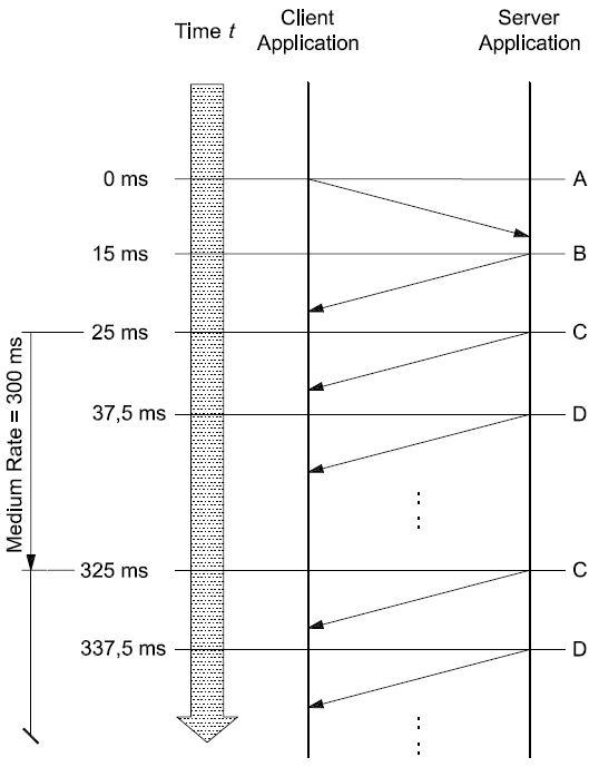
Key
A ReadDataByPeriodicIdentifier (2A, 02, F2E3, F224 hex) request message (sendAtMediumRate)
-
B ReadDataByPeriodicIdentifier positive response message (6A hex, no data included)
-
C ReadDataByPeriodicIdentifier positive response message (6A, E3, xx, …, xx hex)
-
D ReadDataByPeriodicIdentifier positive response message (6A, 24, xx, …, xx hex)
Figure 17 — Example #1 — periodicDataIdentifiers scheduled at medium rate (300 ms)
Table 174 shows a possible implementation of the periodic scheduler in the server. The table contains the periodic scheduler variables and how they change each time the background function that checks the periodic scheduler is executed.
Table 174 — Example #1 — Periodic scheduler table
|
t
(ms)
|
Periodic scheduler transmit index
|
Periodic identifier sent
|
Periodic scheduler loop #
|
Scheduler[0] Transmit Count
|
Scheduler[1] Transmit Count
|
|
25,0
|
0
|
1
|
1
|
0 W 24
|
0
|
|
37,5
|
1
|
2
|
2
|
23
|
0 W 24
|
|
50,0
|
0
|
None
|
3
|
22
|
23
|
|
62,5
|
0
|
None
|
4
|
21
|
22
|
|
75,0
|
0
|
None
|
5
|
20
|
21
|
|
87,5
|
0
|
None
|
6
|
19
|
20
|
|
100,0
|
0
|
None
|
7
|
18
|
19
|
|
112,5
|
0
|
None
|
8
|
17
|
18
|
|
125,0
|
0
|
None
|
9
|
16
|
17
|
|
137,5
|
0
|
None
|
10
|
15
|
16
|
|
150,0
|
0
|
None
|
11
|
14
|
15
|
|
162,5
|
0
|
None
|
12
|
13
|
14
|
|
175,0
|
0
|
None
|
13
|
12
|
13
|
|
187,5
|
0
|
None
|
14
|
11
|
12
|
|
200,0
|
0
|
None
|
15
|
10
|
11
|
|
212,5
|
0
|
None
|
16
|
9
|
10
|
|
225,0
|
0
|
None
|
17
|
8
|
9
|
|
237,5
|
0
|
None
|
18
|
7
|
8
|
|
250,0
|
0
|
None
|
19
|
6
|
7
|
|
262,5
|
0
|
None
|
20
|
5
|
6
|
|
275,0
|
0
|
None
|
21
|
4
|
5
|
|
287,5
|
0
|
None
|
22
|
3
|
4
|
|
300,0
|
0
|
None
|
23
|
2
|
3
|
|
312,5
|
0
|
None
|
24
|
1
|
2
|
|
325,0
|
0
|
1
|
25
|
0 W 24
|
1
|
|
337,5
|
1
|
2
|
26
|
23
|
0 W 24
|
|
350,0
|
0
|
None
|
27
|
22
|
23
|
|
362,5
|
0
|
None
|
28
|
21
|
22
|
-
Example #2 — Read multiple periodicDataIdentifiers at different periodic rates
In this example, three (3) periodicIdentifiers (for simplicity 01 hex, 02 hex, 03 hex) are scheduled at the fast rate and then another request is sent for a single periodicDataIdentifier (04 hex) to be scheduled at the medium rate. For the purposes of this example, the server receives the first ReadDataByPeriodicIdentifier request (A), sends a positive response (B) without any periodic data and executes the periodic scheduler background function for the first time at t = 25,0 ms (C). When the second ReadDataByPeriodicIdentifier request (E) is received, the server sends a positive response (G) without any periodic data and starts executing the periodic scheduler background function at t = 62,5 ms (H) at a scheduled medium rate of 312,5 ms.
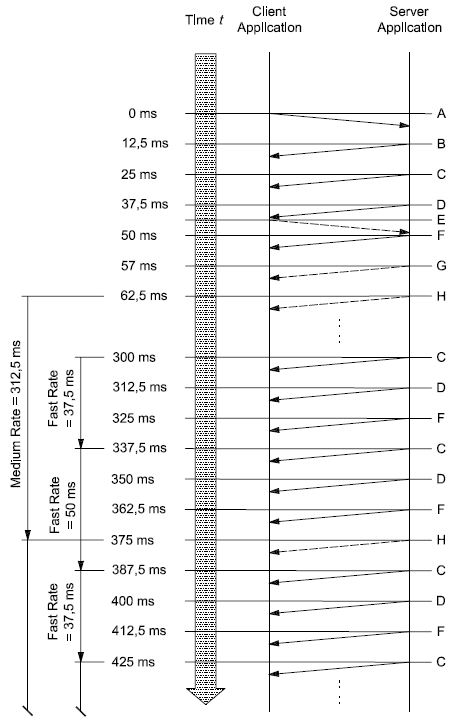
Key
A ReadDataByPeriodicIdentifier (2A, 03, F201, F202, F203 hex) request message (sendAtFastRate) B ReadDataByPeriodicIdentifier positive response message (6A hex, no data included)
C ReadDataByPeriodicIdentifier positive response message (6A, 01, xx, …, xx hex) D ReadDataByPeriodicIdentifier positive response message (6A, 02, xx, …, xx hex)
E ReadDataByPeriodicIdentifier (2A, 02, F204 hex) request message (sendAtMediumRate) F ReadDataByPeriodicIdentifier positive response message (6A, 03, xx, …, xx hex)
G ReadDataByPeriodicIdentifier positive response message (6A hex, no data included) H ReadDataByPeriodicIdentifier positive response message (6A, 04, xx, …, xx hex)
Figure 18 — Example #2 — periodicDataIdentifiers scheduled at fast (25 ms) and medium rate (300 ms)
Table 175 shows a possible implementation of the periodic scheduler in the server. The table contains the periodic scheduler variables and how they change each time the background function that checks the periodic scheduler is executed.
Table 175 — Example #2 — Periodic scheduler table
|
t
(ms)
|
Periodic scheduler transmit index
|
Periodic identifier sent
|
Periodic scheduler loop #
|
Scheduler[0] Transmit Count
|
Scheduler[1] Transmit Count
|
Scheduler[2] Transmit Count
|
Scheduler[3] Transmit Count
|
|
25,0
|
0
|
1
|
1
|
0 W 2
|
0
|
0
|
N/A
|
|
37,5
|
1
|
2
|
2
|
1
|
0 W 2
|
0
|
N/A
|
|
50,0
|
2
|
3
|
3
|
0
|
1
|
0 W 2
|
0
|
|
62,5
|
3
|
4
|
4
|
0
|
0
|
1
|
0 W 24
|
|
75,0
|
0
|
1
|
5
|
0 W 2
|
0
|
0
|
23
|
|
87,5
|
1
|
2
|
6
|
1
|
0 W 2
|
0
|
22
|
|
100,0
|
2
|
3
|
7
|
0
|
1
|
0 W 2
|
21
|
|
112,5
|
3
|
1
|
8
|
0 W 2
|
0
|
1
|
20
|
|
125,0
|
1
|
2
|
9
|
1
|
0 W 2
|
0
|
19
|
|
137,5
|
2
|
3
|
10
|
0
|
1
|
0 W 2
|
18
|
|
150,0
|
3
|
1
|
11
|
0 W 2
|
0
|
1
|
17
|
|
162,5
|
1
|
2
|
12
|
1
|
0 W 2
|
0
|
16
|
|
175,0
|
2
|
3
|
13
|
0
|
1
|
0 W 2
|
15
|
|
187,5
|
3
|
1
|
14
|
0 W 2
|
0
|
1
|
14
|
|
200,0
|
1
|
2
|
15
|
1
|
0 W 2
|
0
|
13
|
|
212,5
|
2
|
3
|
16
|
0
|
1
|
0 W 2
|
12
|
|
225,0
|
3
|
1
|
17
|
0 W 2
|
0
|
1
|
11
|
|
237,5
|
1
|
2
|
18
|
1
|
0 W 2
|
0
|
10
|
|
250,0
|
2
|
3
|
19
|
0
|
1
|
0 W 2
|
9
|
|
262,5
|
3
|
1
|
20
|
0 W 2
|
0
|
1
|
8
|
|
275,0
|
1
|
2
|
21
|
1
|
0 W 2
|
0
|
7
|
|
287,5
|
2
|
3
|
22
|
0
|
1
|
0 W 2
|
6
|
|
300,0
|
3
|
1
|
23
|
0 W 2
|
0
|
1
|
5
|
|
312,5
|
1
|
2
|
24
|
1
|
0 W 2
|
0
|
4
|
|
325,0
|
2
|
3
|
25
|
0
|
1
|
0 W 2
|
3
|
|
337,5
|
3
|
1
|
26
|
0 W 2
|
0
|
1
|
2
|
|
350,0
|
1
|
2
|
27
|
1
|
0 W 2
|
0
|
1
|
|
362,5
|
2
|
3
|
28
|
0
|
1
|
0 W 2
|
0
|
|
375,0
|
3
|
4
|
29
|
0
|
0
|
1
|
0 W 24
|
|
387,5
|
0
|
1
|
30
|
0 W 2
|
0
|
0
|
23
|
-
DynamicallyDefineDataIdentifier (2C hex) service
-
Service description
The DynamicallyDefineDataIdentifier service allows the client to dynamically define in a server a data identifier that can be read via the ReadDataByIdentifier service at a later time.
The intention of this service is to provide the client with the ability to group one or more data elements into a data superset that can be requested en masse via the ReadDataByIdentifier or ReadDataByPeriodicIdentifier service. The data elements to be grouped together can be referenced by either
-
a source data identifier, a position and size, or
-
a memory address and a memory length, or
-
a combination of the two methods listed above using multiple requests to define the single data element. The dynamically defined dataIdentifier will then contain a concatenation of the data parameter definitions.
This service allows greater flexibility in handling ad hoc data needs of the diagnostic application that extend beyond the information that can be read via statically defined data identifiers, and can also be used to reduce bandwidth utilization by avoiding overhead penalty associated with frequent request/response transactions.
The definition of the dynamically defined data identifier can either be done via a single request message or via multiple request messages. This allows for the definition of a single data element referencing source identifier(s) and memory addresses. The server shall concatenate the definitions for the single data element. A redefinition of a dynamically defined data identifier can be achieved by clearing the current definition and starting over with the new definition.
Although this service does not prohibit such functionality, it is not recommended that the client reference one dynamically defined data record from another, because deletion of the referenced record could create data consistency problems within the referencing record.
This service also provides the ability to clear an existing dynamically defined data record. Requests to clear a data record shall be responded to positively if the specified data record identifier is within the range of valid dynamic data identifiers supported by the server (see C.1 for more details).
The server shall maintain the dynamically defined data record until it is cleared or as specified by the vehicle manufacturer (e.g. deletion of dynamically defined data records upon session transition or upon power down of the server).
The server can implement data records in two different ways:
-
composite data records containing multiple elemental data records which are not individually referenced;
-
unique two-byte identification “tags” or parameter identifier (PID) values for individual, elemental data records supported within the server (an example elemental data record, or PID, is engine speed or intake air temperature): this implementation of data records is a subset of a composite data record implementation because it only references a single elemental data record instead of a data record including multiple elemental data records.
Both types of implementing of data records are supported by the DynamicallyDefineDataIdentifier service to define a dynamic data identifier.
-
Composite block of data: the position parameter shall reference the starting point in the composite block of data and the size parameter shall reflect the length of data to be placed in the dynamically defined data identifier. The tester is responsible for including only a portion of an elemental data record of the composite block of data in the dynamic data record.
-
Two-byte PID: the position parameter shall be set to one (1) and the size parameter shall reflect the length of the PID (length of the elemental data record). The tester is responsible to not include only a portion of the two-byte PID value in the dynamic data record.
The ordering of the data within the dynamically defined data record shall be the same as specified in the client request message(s). Also, the first position of the data specified in the client’s request shall be oriented such that it occurs closest to the beginning of the dynamic data record, in accordance with the ordering requirement mentioned in the preceding sentence.
In addition to the definition of a dynamic data identifier via a logical reference (a record data identifier), this service provides the capability to define a dynamically defined data identifier via an absolute memory address and memory length information. This mechanism of defining a dynamic data identifier is recommended to be used only during the development phase of a server.
IMPORTANT — The server and the client shall meet the request and response message behaviour as specified in 7.5.2 in the event that those addressing methods are implemented for this service.
-
Request message
-
Request message definition
Table 176 — Request message definition — Sub-function = defineByIdentifier
|
A_Data byte
|
Parameter name
|
Cvt
|
Hex value
|
Mnemonic
|
|
#1
|
DynamicallyDefineDataIdentifier Request Service Id
|
M
|
2C
|
DDDI
|
|
#2
|
sub-function = [
defineByIdentifier ]
|
M
|
01
|
LEV_ DBID
|
|
#3
#4
|
dynamicallyDefinedDataIdentifier[] = [
byte#1 (MSB) byte#2 (LSB) ]
|
M M
|
F2,F3 00-FF
|
DDDDI_ HB LB
|
|
#5
#6
|
sourceDataIdentifier[] #1 = [
byte#1 (MSB) byte#2 (LSB) ]
|
M M
|
00-FF
00-FF
|
SDI_ HB LB
|
|
#7
|
positionInSourceDataRecord #1
|
M
|
01-FF
|
PISDR1
|
|
#8
|
memorySize #1
|
M
|
00-FF
|
MS1
|
|
:
|
:
|
:
|
:
|
:
|
|
#n-3
#n-2
|
sourceDataIdentifier[] #m = [
byte#1 (MSB) byte#2 (LSB) ]
|
U U
|
00-FF
00-FF
|
SDI_ HB LB
|
|
#n-1
|
positionInSourceDataRecord #m
|
U
|
01-FF
|
PISDRm
|
|
#n
|
memorySize #m
|
U
|
00-FF
|
MSm
|
Table 177 — Request message definition — Sub-function = defineByMemoryAddress
|
A_Data byte
|
Parameter name
|
Cvt
|
Hex value
|
Mnemonic
|
|
#1
|
DynamicallyDefineDataIdentifier Request Service Id
|
M
|
2C
|
DDDI
|
|
#2
|
sub-functio
|
n = [
defineByMemoryAddress ]
|
M
|
02
|
LEV_ DBMA
|
|
#3
|
dynamicallyDefinedDataIdentifier[] = [
byte#1 (MSB) byte#2 (LSB) ]
|
M
|
F2,F3
|
DDDDI_
|
|
HB
|
|
#4
|
M
|
00-FF
|
LB
|
|
#5
|
addressAndLengthFormatIdentifier
|
Ma 1
|
00-FF
|
ALFID
|
|
#6
|
memoryAd
|
dress[] = [
byte#1 (MSB)
:
byte#m ]
|
M
|
00-FF
|
MA_
|
|
B1
|
|
:
|
:
|
:
|
:
|
|
#(m-1)+6
|
Cb 1
|
00-FF
|
Bm
|
|
#m+6
|
memorySize[] = [
byte#1 (MSB)
:
byte#k ]
|
M
|
00-FF
|
MS_
|
|
B1
|
|
:
|
:
|
:
|
:
|
|
#m+6+(k-1)
|
Cc 2
|
00-FF
|
Bk
|
|
:
|
:
|
:
|
:
|
:
|
|
#n-k-(m-1)
|
memoryAd
|
dress[] = [
byte#1 (MSB)
:
byte#m ]
|
U
|
00-FF
|
MA_
|
|
B1
|
|
:
|
:
|
:
|
:
|
|
#n-k
|
U/C1
|
00-FF
|
Bm
|
|
#n-(k-1)
|
memorySize[] = [
byte#1 (MSB)
:
byte#k ]
|
U
|
00-FF
|
MS_
|
|
B1
|
|
:
|
:
|
:
|
:
|
|
#n
|
U/C2
|
00-FF
|
Bk
|
| |
-
M1, the addressAndLengthFormatIdentifier parameter, is only present once at the very beginning of the request message and defines the length of the address and length information for each memory location reference throughout the whole request message.
-
The presence of the C1parameter depends on the address length information parameter of the addressAndLengthFormatIdentifier.
-
The presence of the C2parameter depends on the memory size length information of the addressAndLengthFormatIdentifier.
Table 178 — Request message definition — Sub-function = clearDynamicallyDefinedDataIdentifier
|
A_Data byte
|
Parameter name
|
Cvt
|
Hex value
|
Mnemonic
|
|
#1
|
DynamicallyDefineDataIdentifier Request Service Id
|
M
|
2C
|
DDDI
|
|
#2
|
sub-function = [
clearDynamicallyDefinedDataIdentifier ]
|
M
|
03
|
LEV_ CDDDID
|
|
#3
#4
|
dynamicallyDefinedDataIdentifier[] = [
byte#1 (MSB) byte#2 (LSB) ]
|
Ca C
|
F2,F3 00-FF
|
DDDDI_ HB LB
|
|
a The presence of the C parameter requires the server to clear the dynamicallyDefinedDataIdentifier included in byte#1 and byte#2. If the parameter is not present all dynamicallyDefinedDataIdentifier in the server shall be cleared.
|
-
Request message sub-function parameter $Level (LEV_) definition
The sub-parameters defined as valid for the request message of this service are indicated in Table 179 [suppressPosRspMsgIndicationBit (bit 7) not shown].
Table 179 — Request message sub-function parameter definition
|
Hex (bit 6-0)
|
Description
|
Cvt
|
Mnemonic
|
|
00
|
ISOSAEReserved
This value is reserved by this document for future definition.
|
M
|
ISOSAERESRVD
|
|
01
|
defineByIdentifier
This value shall be used to specify to the server that definition of the dynamic data identifier shall occur via a data identifier reference.
|
U
|
DBID
|
|
02
|
defineByMemoryAddress
This value shall be used to specify to the server that definition of the dynamic data identifier shall occur via an address reference.
Note that this sub-function shall only be used during the development phase of the server.
|
U
|
DBMA
|
|
03
|
clearDynamicallyDefinedDataIdentifier
This value shall be used to clear the specified dynamic data identifier. Note that the server shall positively respond to a clear request from the client, even if the specified dynamic data identifier doesn’t exist at the time of the request. However, the specified dynamic data identifier shall be within a valid range (see C.1 for allowable ranges). If the specified dynamic data identifier is being reported periodically at the time of the request, the dynamic identifier shall first be stopped and then cleared.
|
U
|
CDDDI
|
|
04-7F
|
ISOSAEReserved
This range of values is reserved by this document for future definition.
|
M
|
ISOSAERESRVD
|
-
Request message data parameter definition
The following data parameters are defined for this service.
Table 180 — Request message data parameter definition
|
Definition
|
|
dynamicallyDefinedDataIdentifier
This parameter specifies how the dynamic data record which is being defined by the client will be referenced in future calls to the service ReadDataByIdentifier or ReadDataByPeriodicDataIdentifier. The dynamicallyDefinedDataIdentifier shall be handled as a dataIdentifier in the ReadDataByIdentifier service (see C.1 for further details). It shall be handled as a periodicRecordIdentifier in the ReadDataByPeriodicDataIdentifier service (see the ReadDataByPeriodicDataIdentifier service for requirements on the value of this parameter in order to be able to request the dynamically defined data identifier periodically).
|
|
sourceDataIdentifier
This parameter is only present for sub-function = defineByIdentifier. This parameter logically specifies the source of information to be included into the dynamic data record. For example, this could be a 2/3-byte PID identifier used to reference engine speed or a 2/3-byte data record identifier used to reference a composite block of information containing engine speed, vehicle speed, intake air temperature, etc. (see C.1 for further details).
|
|
positionInSourceDataRecord
This parameter is only present for sub-function = defineByIdentifier. This one-byte parameter is used to specify the starting byte position of the excerpt of the source data record to be included in the dynamic data record. A position of one
(1) shall reference the first byte of the data record referenced by the sourceDataIdentifier.
|
|
addressAndLengthFormatIdentifier
This parameter is a one-byte value with each nibble encoded separately (see G.1 for example values):
|
|
memoryAddress
This parameter is only present for sub-function = defineByMemoryAddress. This parameter specifies the memory source address of information to be included into the dynamic data record. The number of bytes used for this address is defined by the low nibble (bit 3 - 0) of the addressFormatIdentifier.
|
|
memorySize
This parameter is used to specify the total number of bytes from the source data record/memory address that are to be included in the dynamic data record.
In case of sub-function = defineByIdentifier, then the positionInSourceDataRecord parameter is used in addition to specify the starting position in the source data identifier from which the memorySize applies. The number of bytes used for this size is one (1) byte.
In case of sub-function = defineByMemoryAddress, then this parameter reflects the number of bytes to be included in the dynamically defined data identifier starting at the specified memoryAddress. The number of bytes used for this size is defined by the high nibble (bit 7 - 4) of the addressFormatIdentifier.
|
-
Positive response message
-
Positive response message definition
Table 181 — Positive response message definition
|
A_Data byte
|
Parameter name
|
Cvt
|
Hex value
|
Mnemonic
|
|
#1
|
DynamicallyDefineDataIdentifier Response Service Id
|
M
|
6C
|
DDDIPR
|
|
#2
|
definitionType
|
M
|
00-7F
|
DM
|
|
#3
#4
|
dynamicallyDefinedDataIdentifier [] = [
byte#1 (MSB) byte#2 (LSB) ]
|
Ca C
|
F2,F3 00-FF
|
DDDDI_ HB LB
|
|
a The presence of the C parameter is required if the dynamicallyDefinedDataIdentifier parameter is present in the request message, otherwise the parameter shall not be included.
|
-
Positive response message data parameter definition
Table 182 — Response message data parameter definition
|
Definition
|
|
definitionType
This parameter is an echo of bits 6 - 0 of the sub-function parameter from the request message.
|
|
dynamicallyDefinedDataIdentifier
This parameter is an echo of the data parameter dynamicallyDefinedDataIdentifier from the request message.
|
-
Supported negative response codes (NRC_)
The following negative response codes shall be implemented for this service. The circumstances under which each response code would occur are documented in Table 183.
Table 183 — Supported negative response codes
|
Hex
|
Description
|
Cvt
|
Mnemonic
|
|
12
|
subFunctionNotSupported
This response code shall be sent if the sub-function parameter is not supported.
|
M
|
SFNS
|
|
13
|
incorrectMessageLengthOrInvalidFormat
The length of the message is wrong.
|
M
|
IMLOIF
|
|
22
|
conditionsNotCorrect
This response code shall be sent if the operating conditions of the server to perform the required action are not met.
|
M
|
CNC
|
|
31
|
requestOutOfRange
This response code shall be sent if:
|
M
|
ROOR
|
|
33
|
securityAccessDenied
This code shall be sent if:
|
M
|
SAD
|
-
any data identifier (dynamicallyDefinedDataIdentifier or any sourceDataIdentifier) in the request message is not supported/invalid;
-
the positionInSourceDataRecord is incorrect (less than 1 or greater than the maximum allowed by the server);
-
any memory address in the request message is not supported in the server;
-
the specified memorySize is invalid;
-
the amount of data to be packed into the dynamic data identifier exceeds the maximum allowed by the server;
-
the specified addressAndLengthFormatIdentifier is not valid.
-
any data identifier (dynamicallyDefinedDataIdentifier or any sourceDataIdentifier) in the request message is secured and the server is not in an unlocked state;
-
any memory address in the request message is secured and the server is not in an unlocked state.
-
Message flow examples DynamicallyDefineDataIdentifier
-
Assumptions
This subclause specifies the conditions to be fulfilled for the example to perform a DynamicallyDefineDataIdentifier service.
The service in this example is not limited by any restriction of the server.
In the first example, the server supports two-byte identifiers (PIDs) which reference a single data information. The example builds a dynamic data identifier using the defineByIdentifier method and then sends a ReadDataByIdentifier request to read the dynamic data identifier which has just been defined.
In the second example, the server supports data identifiers which reference a composite block of data containing multiple data information. The example builds a dynamic identifier also using the defineByIdentifier method and sends a ReadDataByIdentifier request to read the data identifier whihc has just been defined.
The third example builds a dynamic data identifier using the defineByMemoryAddress method and sends a ReadDataByIdentifier request to read the data identifier which has just been defined.
In the fourth example, the server supports data identifiers which reference a composite block of data containing multiple data information. The example builds a dynamic data identifier using the defineByIdentifier method and then uses the ReadDataByPeriodicIdentifier service to request the dynamically defined data identifier to be sent periodically by the server.
The fifth example demonstrates the deletion of a dynamically defined data identifier.
Table 184 shall be used for the examples below. Note that the values being reported may change over time on a real vehicle, but are shown to be constants for the sake of clarity.
Refer to ISO 15031-2 for further details regarding accepted terms/definitions/acronyms for emissions-related systems.
For all examples, the client requests a response message by setting the suppressPosRspMsgIndicationBit (bit 7 of the sub-function parameter) to “FALSE” (‘0’).
Table 184 — Composite data blocks — DataIdentifier definitions
|
Data identifier (block, hex)
|
Data byte
|
Data record contents
|
Byte value (hex)
|
|
010A
|
#1
|
dataRecord [ data#1 ] = B+
|
8C
|
|
#2
|
dataRecord [ data#2 ] = ECT
|
A6
|
|
#3
|
dataRecord [ data#3 ] = TP
|
66
|
|
#4
|
dataRecord [ data#4 ] = RPM
|
07
|
|
#5
|
dataRecord [ data#5 ] = RPM
|
50
|
|
#6
|
dataRecord [ data#6 ] = MAP
|
20
|
|
#7
|
dataRecord [ data#7 ] = MAF
|
1A
|
|
#8
|
dataRecord [ data#8 ] = VSS
|
00
|
|
#9
|
dataRecord [ data#9 ] = BARO
|
63
|
|
#10
|
dataRecord [ data#10 ] = LOAD
|
4A
|
|
#11
|
dataRecord [ data#11 ] = IAC
|
82
|
|
#12
|
dataRecord [ data#12 ] = APP
|
7E
|
|
050B
|
#1
|
dataRecord [ data#1 ] = SPARKADV
|
00
|
|
#2
|
dataRecord [ data#2 ] = KS
|
91
|
Table 185 — Elemental data records - PID definitions
|
Data identifier (PID, hex)
|
Data byte
|
Data record contents
|
Byte value (hex)
|
|
1234
|
#1
|
EOT (MSB)
|
4C
|
|
#2
|
EOT (LSB)
|
36
|
|
5678
|
#1
|
AAT
|
4D
|
|
9ABC
|
#1
|
EOL (MSB)
|
49
|
|
#2
|
EOL
|
21
|
|
#3
|
EOL
|
00
|
|
#4
|
EOL (LSB)
|
17
|
Table 186 — Memory data records — Memory Address definitions
|
Memory address (hex)
|
Data byte
|
Data record contents
|
Byte value (hex)
|
|
21091968
|
#1
|
dataRecord [ data#1 ] = B+
|
8C
|
|
#2
|
dataRecord [ data#2 ] = ECT
|
A6
|
|
#3
|
dataRecord [ data#3 ] = TP
|
66
|
|
#4
|
dataRecord [ data#4 ] = RPM
|
07
|
|
#5
|
dataRecord [ data#5 ] = RPM
|
50
|
|
#6
|
dataRecord [ data#6 ] = MAP
|
20
|
|
#7
|
dataRecord [ data#7 ] = MAF
|
1A
|
|
#8
|
dataRecord [ data#8 ] = VSS
|
00
|
|
#9
|
dataRecord [ data#9 ] = BARO
|
63
|
|
#10
|
dataRecord [ data#10 ] = LOAD
|
4A
|
|
#11
|
dataRecord [ data#11 ] = IAC
|
82
|
|
#12
|
dataRecord [ data#12 ] = APP
|
7E
|
|
13101994
|
#1
|
dataRecord [ data#1 ] = SPARKADV
|
00
|
|
#2
|
dataRecord [ data#2 ] = KS
|
91
|
-
Example #1 — DynamicallyDefineDataIdentifier, sub-function = defineByIdentifier
This example will build up a dynamically defined data identifier (DDDDI F301 hex) containing engine oil temperature, ambient air temperature and engine oil level using the two-byte PIDs as the reference for the required data.
Table 187 — DynamicallyDefineDataIdentifier request DDDI F301 hex message flow example #1
|
Message direction:
|
client server
|
|
Message type:
|
Request
|
|
A_Data byte
|
Description (all values are in hexadecimal)
|
Byte value (hex)
|
Mnemonic
|
|
#1
|
DynamicallyDefineDataIdentifier request SID
|
2C
|
DDDI
|
|
#2
|
sub-function = defineByIdentifier, suppressPosRspMsgIndicationBit = FALSE
|
01
|
DBID
|
|
#3
#4
|
dynamicallyDefinedDataIdentifier [ byte#1 ] (MSB)
dynamicallyDefinedDataIdentifier [ byte#2 ] (LSB)
|
F3
01
|
DDDDI_B1
DDDDI_B2
|
|
#5
#6
|
sourceDataIdentifier #1 [ byte#1 ] (MSB) - Engine Oil Temperature
sourceDataIdentifier #1 [ byte#2 ]
|
12
34
|
SDI_B1
SDI_B2
|
|
#7
|
positionInSourceDataRecord #1
|
1
|
PISDR#1
|
|
#8
|
memorySize #1
|
2
|
MS#1
|
|
#9
#10
|
sourceDataIdentifier #2 [ byte#1 ] (MSB) - Ambient Air Temperature
sourceDataIdentifier #2 [ byte#2 ]
|
56
78
|
SDI_B1
SDI_B2
|
|
#11
|
positionInSourceDataRecord #2
|
1
|
PISDR#2
|
|
#12
|
memorySize #2
|
1
|
MS#2
|
|
#13
#14
|
sourceDataIdentifier #3 [ byte#1 ] (MSB) - Engine Oil Level
sourceDataIdentifier #3 [ byte#2 ]
|
9A
BC
|
SDI_B1
SDI_B2
|
|
#15
|
positionInSourceDataRecord #3
|
1
|
PISDR#3
|
|
#16
|
memorySize #3
|
4
|
MS#3
|
Table 188 — DynamicallyDefineDataIdentifier positive response DDDI F301 hex message flow example #1
|
Message direction:
|
server client
|
|
Message type:
|
Response
|
|
A_Data byte
|
Description (all values are in hexadecimal)
|
Byte value (hex)
|
Mnemonic
|
|
#1
|
DynamicallyDefineDataIdentifier response SID
|
6C
|
DDDIPR
|
|
#2
|
definitionMode = defineByIdentifier
|
01
|
DBID
|
|
#3
#4
|
dynamicallyDefinedDataIdentifier [ byte#1 ] (MSB)
dynamicallyDefinedDataIdentifier [ byte#2 ] (LSB)
|
F3
01
|
DDDDI_B1
DDDDI_B2
|
Table 189 — ReadDataByIdentifier request DDDI F301 hex message flow example #1
|
Message direction:
|
client server
|
|
Message type:
|
Request
|
|
A_Data byte
|
Description (all values are in hexadecimal)
|
Byte value (hex)
|
Mnemonic
|
|
#1
|
ReadDataByIdentifier request SID
|
22
|
RDBI
|
|
#2
#3
|
dataIdentifier [ byte#1 ] (MSB)
dataIdentifier [ byte#2 ] (LSB)
|
F3
01
|
DID_B1
DID_B2
|
Table 190 — ReadDataByIdentifier positive response DDDI F301 hex message flow example #1
|
Message direction:
|
server client
|
|
Message type:
|
Response
|
|
A_Data byte
|
Description (all values are in hexadecimal)
|
Byte value (hex)
|
Mnemonic
|
|
#1
|
ReadDataByIdentifier response SID
|
62
|
RDBIPR
|
|
#2
|
dataIdentifier [ byte#1 ] (MSB)
|
F3
|
DID_B1
|
|
#3
|
dataIdentifier [ byte#2 ] (LSB)
|
01
|
DID_B2
|
|
#4
|
dataRecord [ data#1 ] = EOT
|
4C
|
DREC_DATA_1
|
|
#5
|
dataRecord [ data#2 ] = EOT
|
36
|
DREC_DATA_2
|
|
#6
|
dataRecord [ data#3 ] = AAT
|
4D
|
DREC_DATA_3
|
|
#7
|
dataRecord [ data#4 ] = EOL
|
49
|
DREC_DATA_4
|
|
#8
|
dataRecord [ data#5 ] = EOL
|
21
|
DREC_DATA_5
|
|
#9
|
dataRecord [ data#6 ] = EOL
|
00
|
DREC_DATA_6
|
|
#10
|
dataRecord [ data#7 ] = EOL
|
17
|
DREC_DATA_7
|
-
Example #2 — DynamicallyDefineDataIdentifier — sub-function = defineByIdentifier
This example will build up a dynamic data identifier (DDDI F302 hex) containing engine coolant temperature (from data record 010A hex), engine speed (from data record 010A hex), IAC Pintle Position (from data record 010A hex) and knock sensor (from data record 050B hex).
Table 191 — DynamicallyDefineDataIdentifier request DDDI F302 hex message flow example #2
|
Message direction:
|
client server
|
|
Message type:
|
Request
|
|
A_Data byte
|
Description (all values are in hexadecimal)
|
Byte value (hex)
|
Mnemonic
|
|
#1
|
DynamicallyDefineDataIdentifier request SID
|
2C
|
DDDI
|
|
#2
|
sub-function = defineByIdentifier, suppressPosRspMsgIndicationBit = FALSE
|
01
|
DBID
|
|
#3
#4
|
dynamicallyDefinedDataIdentifier [ byte#1 ] (MSB)
dynamicallyDefinedDataIdentifier [ byte#2 ] (LSB)
|
F3
02
|
DDDDI_B1
DDDDI_B2
|
|
#5
#6
|
sourceDataIdentifier #1 [ byte#1 ] (MSB)
sourceDataIdentifier #1 [ byte#2 ] (LSB)
|
01
0A
|
SDI_B1
SDI_B2
|
|
#7
|
positionInSourceDataRecord #1 - Engine Coolant Temperature
|
02
|
PISDR#1
|
|
#8
|
memorySize #1
|
01
|
MS#1
|
|
#9
#10
|
sourceDataIdentifier #2 [ byte#1 ] (MSB)
sourceDataIdentifier #2 [ byte#2 ] (LSB)
|
01
0A
|
SDI_B1
SDI_B2
|
|
#11
|
positionInSourceDataRecord #2 - Engine Speed
|
04
|
PISDR#2
|
|
#12
|
memorySize #2
|
02
|
MS#2
|
|
#13
#14
|
sourceDataIdentifier #3 [ byte#1 ] (MSB)
sourceDataIdentifier #3 [ byte#2 ] (LSB)
|
01
0A
|
SDI_B1
SDI_B2
|
|
#15
|
positionInSourceDataRecord #3 – Idle Air Control
|
0B
|
PISDR#3
|
|
#16
|
memorySize #3
|
01
|
MS#3
|
|
#17
#18
|
sourceDataIdentifier #4 [ byte#1 ] (MSB)
sourceDataIdentifier #4 [ byte#2 ] (LSB)
|
05
0B
|
SDI_B1
SDI_B2
|
|
#19
|
positionInSourceDataRecord #4 - Knock Sensor
|
02
|
PISDR#4
|
|
#20
|
memorySize #4
|
01
|
MS#4
|
Table 192 — DynamicallyDefineDataIdentifier positive response DDDI F302 hex message flow example #2
|
Message direction:
|
server client
|
|
Message type:
|
Response
|
|
A_Data byte
|
Description (all values are in hexadecimal)
|
Byte value (hex)
|
Mnemonic
|
|
#1
|
DynamicallyDefineDataIdentifier response SID
|
6C
|
DDDIPR
|
|
#2
|
definitionMode = defineByIdentifier
|
01
|
DBID
|
|
#3
#4
|
dynamicallyDefinedDataIdentifier [ byte#1 ] (MSB)
dynamicallyDefinedDataIdentifier [ byte#2 ] (LSB)
|
F3
02
|
DDDDI_B1
DDDDI_B2
|
Table 193 — ReadDataByIdentifier request DDDI F302 hex message flow example #2
|
Message direction:
|
client server
|
|
Message type:
|
Request
|
|
A_Data byte
|
Description (all values are in hexadecimal)
|
Byte value (hex)
|
Mnemonic
|
|
#1
|
ReadDataByIdentifier request SID
|
22
|
RDBI
|
|
#2
#3
|
dataIdentifier [ byte#1 ] (MSB)
dataIdentifier [ byte#2 ] (LSB)
|
F3
02
|
DID_B1
DID_B2
|
Table 194 — ReadDataByIdentifier positive response DDDI F302 hex message flow example #2
|
Message direction:
|
server client
|
|
Message type:
|
Response
|
|
A_Data byte
|
Description (all values are in hexadecimal)
|
Byte value (hex)
|
Mnemonic
|
|
#1
|
ReadDataByIdentifier response SID
|
62
|
RDBIPR
|
|
#2
|
dataIdentifier [ byte#1 ] (MSB)
|
F3
|
DID_B1
|
|
#3
|
dataIdentifier [ byte#2 ] (LSB)
|
02
|
DID_B2
|
|
#4
|
dataRecord [ data#1 ] = ECT
|
A6
|
DREC_DATA_1
|
|
#5
|
dataRecord [ data#2 ] = RPM
|
07
|
DREC_DATA_2
|
|
#6
|
dataRecord [ data#3 ] = RPM
|
50
|
DREC_DATA_3
|
|
#7
|
dataRecord [ data#4 ] = IAC
|
82
|
DREC_DATA_4
|
|
#8
|
dataRecord [ data#5 ] = KS
|
91
|
DREC_DATA_5
|
-
Example #3 — DynamicallyDefineDataIdentifier — sub-function = defineByMemoryAddress
This example will build up a dynamic data identifier (DDDI F302 hex) containing engine coolant temperature (from a memory block starting at memory address 21091969 hex), engine speed (from a memory block starting at memory address 2109196B hex) and knock sensor (from a memory block starting at memory address 13101995 hex).
Table 195 — DynamicallyDefineDataIdentifier request DDDI F302 hex message flow example #3
|
Message direction:
|
client server
|
|
Message type:
|
Request
|
|
A_Data byte
|
Description (all values are in hexadecimal)
|
Byte value (hex)
|
Mnemonic
|
|
#1
|
DynamicallyDefineDataIdentifier request SID
|
2C
|
DDDI
|
|
#2
|
sub-function = defineByMemoryAddress, suppressPosRspMsgIndicationBit = FALSE
|
02
|
DBMA
|
|
#3
|
dynamicallyDefinedDataIdentifier [ byte#1 ] (MSB)
|
F3
|
DDDDI_B1
|
|
#4
|
dynamicallyDefinedDataIdentifier [ byte#2 ] (LSB)
|
02
|
DDDDI_B2
|
|
#5
|
addressAndLengthFormatIdentifier
|
14
|
ALFID
|
|
#6
|
memoryAddress #1 [ byte#1 ] (MSB) - Engine coolant temperature
|
21
|
MA_1_B1
|
|
#7
|
memoryAddress #1 [ byte#2 ]
|
09
|
MA_1_B2
|
|
#8
|
memoryAddress #1 [ byte#3 ]
|
19
|
MA_1_B3
|
|
#9
|
memoryAddress #1 [ byte#4 ]
|
69
|
MA_1_B4
|
|
#10
|
memorySize #1
|
01
|
MS#1
|
|
#11
|
memoryAddress #2 [ byte#1 ] (MSB) - Engine speed
|
21
|
MA_2_B1
|
|
#12
|
memoryAddress #2 [ byte#2 ]
|
09
|
MA_2_B2
|
|
#13
|
memoryAddress #2 [ byte#3 ]
|
19
|
MA_2_B3
|
|
#14
|
memoryAddress #2 [ byte#4 ]
|
6B
|
MA_2_B4
|
|
#15
|
memorySize #2
|
02
|
MS#2
|
|
#16
|
memoryAddress #3 [ byte#1 ] (MSB) - Knock sensor
|
13
|
MA_3_B1
|
|
#17
|
memoryAddress #3 [ byte#2 ]
|
10
|
MA_3_B2
|
|
#18
|
memoryAddress #3 [ byte#3 ]
|
19
|
MA_3_B3
|
|
#19
|
memoryAddress #3 [ byte#4 ]
|
95
|
MA_3_B4
|
|
#20
|
memorySize #3
|
01
|
MS#3
|
Table 196 — DynamicallyDefineDataIdentifier positive response DDDI F302 hex message flow example #3
|
Message direction:
|
server client
|
|
Message type:
|
Response
|
|
A_Data byte
|
Description (all values are in hexadecimal)
|
Byte value (hex)
|
Mnemonic
|
|
#1
|
DynamicallyDefineDataIdentifier response SID
|
6C
|
DDDIPR
|
|
#2
|
definitionMode = defineByMemoryAddress
|
02
|
DBMA
|
|
#3
#4
|
dynamicallyDefinedDataIdentifier [ byte#1 ] (MSB)
dynamicallyDefinedDataIdentifier [ byte#2 ] (LSB)
|
F3
02
|
DDDDI_B1
DDDDI_B2
|
Table 197 — ReadDataByIdentifier request DDDI F302 hex message flow example #3
|
Message direction:
|
client server
|
|
Message type:
|
Request
|
|
A_Data byte
|
Description (all values are in hexadecimal)
|
Byte value (hex)
|
Mnemonic
|
|
#1
|
ReadDataByIdentifier request SID
|
22
|
RDBI
|
|
#2
#3
|
dataIdentifier [ byte#1 ] (MSB)
dataIdentifier [ byte#2 ] (LSB)
|
F3
02
|
DID_B1
DID_B2
|
Table 198 — ReadDataByIdentifier positive response DDDI F302 hex message flow example #3
|
Message direction:
|
server client
|
|
Message type:
|
Response
|
|
A_Data byte
|
Description (all values are in hexadecimal)
|
Byte value (hex)
|
Mnemonic
|
|
#1
|
ReadDataByIdentifier response SID
|
62
|
RDBIPR
|
|
#2
|
dataIdentifier [ byte#1 ] (MSB)
|
F3
|
DID_B1
|
|
#3
|
dataIdentifier [ byte#2 ] (LSB)
|
02
|
DID_B2
|
|
#4
|
dataRecord [ data#1 ] = ECT
|
A6
|
DREC_DATA_1
|
|
#5
|
dataRecord [ data#2 ] = RPM
|
07
|
DREC_DATA_2
|
|
#6
|
dataRecord [ data#3 ] = RPM
|
50
|
DREC_DATA_3
|
|
#7
|
dataRecord [ data#4 ] = KS
|
91
|
DREC_DATA_4
|
-
Example #4 — DynamicallyDefineDataIdentifier — sub-function = defineByIdentifier
This example will build up a dynamic data identifier (DDDI F2E7 hex) containing engine coolant temperature (from data record 010A hex), engine speed (from data record 010A hex) and knock sensor (from data record 050B hex).
The value for the dynamic data identifier is chosen out of the range that can be used to request data periodically. Following the definition of the dynamic data identifier the client requests the data identifier to be sent periodically (fast rate).
Table 199 — DynamicallyDefineDataIdentifier request DDDI F2E7 hex message flow example #4
|
Message direction:
|
client server
|
|
Message type:
|
Request
|
|
A_Data byte
|
Description (all values are in hexadecimal)
|
Byte value (hex)
|
Mnemonic
|
|
#1
|
DynamicallyDefineDataIdentifier request SID
|
2C
|
DDDI
|
|
#2
|
sub-function = defineByIdentifier, suppressPosRspMsgIndicationBit = FALSE
|
01
|
DBID
|
|
#3
#4
|
dynamicallyDefinedDataIdentifier [ byte#1 ] (MSB)
dynamicallyDefinedDataIdentifier [ byte#2 ] (LSB)
|
F2
E7
|
DDDDI_B1
DDDDI_B2
|
|
#5
#6
|
sourceDataIdentifier #1 [ byte#1 ] (MSB)
sourceDataIdentifier #1 [ byte#2 ] (LSB)
|
01
0A
|
SDI_B1
SDI_B2
|
|
#7
|
positionInSourceDataRecord #1 - Engine coolant temperature
|
02
|
PISDR
|
|
#8
|
memorySize #1
|
01
|
MS#1
|
|
#9
#10
|
sourceDataIdentifier #2 [ byte#1 ] (MSB)
sourceDataIdentifier #2 [ byte#2 ] (LSB)
|
01
0A
|
SDI_B1
SDI_B2
|
|
#11
|
positionInSourceDataRecord #2 - Engine speed
|
04
|
PISDR
|
|
#12
|
memorySize #2
|
02
|
MS#2
|
|
#13
#14
|
sourceDataIdentifier #3 [ byte#1 ] (MSB)
sourceDataIdentifier #3 [ byte#2 ] (LSB)
|
05
0B
|
SDI_B1
SDI_B2
|
|
#15
|
positionInSourceDataRecord #3 - Knock Sensor
|
02
|
PISDR
|
|
#16
|
memorySize #3
|
01
|
MS#3
|
Table 200 — DynamicallyDefineDataIdentifier positive response DDDI F2E7 hex message flow example #4
|
Message direction:
|
server client
|
|
Message type:
|
Response
|
|
A_Data byte
|
Description (all values are in hexadecimal)
|
Byte value (hex)
|
Mnemonic
|
|
#1
|
DynamicallyDefineDataIdentifier response SID
|
6C
|
DDDIPR
|
|
#2
|
definitionMode = defineByIdentifier
|
01
|
DBID
|
|
#3
#4
|
dynamicallyDefinedDataIdentifier [ byte#1 ] (MSB)
dynamicallyDefinedDataIdentifier [ byte#2 ] (LSB)
|
F2
E7
|
DDDDI_B1
DDDDI_B2
|
Table 201 — ReadDataByPeriodicIdentifier request DDDI F2E7 hex message flow example #4
|
Message direction:
|
client server
|
|
Message type:
|
Request
|
|
A_Data byte
|
Description (all values are in hexadecimal)
|
Byte value (hex)
|
Mnemonic
|
|
#1
|
ReadDataByPeriodicIdentifier request SID
|
2A
|
RDBPI
|
|
#2
|
transmissionMode = sendAtFastRate
|
04
|
TM
|
|
#3
|
PeriodicDataIdentifier
|
E7
|
PDID
|
Table 202 — ReadDataByPeriodicIdentifier initial positive message flow example #4
|
Message direction:
|
server client
|
|
Message type:
|
Response
|
|
A_Data byte
|
Description (all values are in hexadecimal)
|
Byte value (hex)
|
Mnemonic
|
|
#1
|
ReadDataByIdentifier response SID
|
6A
|
RDBPIPR
|
Table 203 — ReadDataByPeriodicIdentifier positive response #1 DDDI F2E7 hex message flow example #4
|
Message direction:
|
server client
|
|
Message type:
|
Response
|
|
A_Data byte
|
Description (all values are in hexadecimal)
|
Byte value (hex)
|
Mnemonic
|
|
#1
|
ReadDataByPeriodicIdentifier response SID
|
6A
|
RDBPIPR
|
|
#2
|
PeriodicDataIdentifier
|
E7
|
PDID
|
|
#3
|
dataRecord [ data#1 ] = ECT
|
A6
|
DREC_DATA_1
|
|
#4
|
dataRecord [ data#2 ] = RPM
|
07
|
DREC_DATA_2
|
|
#5
|
dataRecord [ data#3 ] = RPM
|
50
|
DREC_DATA_3
|
|
#6
|
dataRecord [ data#4 ] = KS
|
91
|
DREC_DATA_4
|
Table 204 — ReadDataByPeriodicIdentifier positive response #n DDDI F2E7 hex message flow example #4
|
Message direction:
|
server client
|
|
Message type:
|
Response
|
|
A_Data byte
|
Description (all values are in hexadecimal)
|
Byte value (hex)
|
Mnemonic
|
|
#1
|
ReadDataByPeriodicIdentifier response SID
|
6A
|
RDBPIPR
|
|
#2
|
periodicDataIdentifier
|
E7
|
PDID
|
|
#3
|
dataRecord [ data#1 ] = ECT
|
A6
|
DREC_DATA_1
|
|
#4
|
dataRecord [ data#2 ] = RPM
|
07
|
DREC_DATA_2
|
|
#5
|
dataRecord [ data#3 ] = RPM
|
55
|
DREC_DATA_3
|
|
#6
|
dataRecord [ data#4 ] = KS
|
98
|
DREC_DATA_4
|
-
Example #5 — DynamicallyDefineDataIdentifier — sub-function = clearDynamicallyDefined- DataIdentifier
This example demonstrates the clearing of a dynamicallyDefinedDataIdentifier and assumes that DDDI F303 hex exists at the time of the request.
Table 205 — DynamicallyDefineDataIdentifier request clear DDDI F303 hex message flow example #5
|
Message direction:
|
client server
|
|
Message type:
|
Request
|
|
A_Data byte
|
Description (all values are in hexadecimal)
|
Byte value (hex)
|
Mnemonic
|
|
#1
|
DynamicallyDefineDataIdentifier request SID
|
2C
|
DDDI
|
|
#2
|
sub-function = clearDynamicallyDefinedDataIdentifier, suppressPosRspMsgIndicationBit = FALSE
|
03
|
CDDDI
|
|
#3
#4
|
dynamicallyDefinedDataIdentifier [ byte#1 ] (MSB)
dynamicallyDefinedDataIdentifier [ byte#2 ] (LSB)
|
F3
03
|
DDDDI_B1
DDDDI_B2
|
Table 206 — DynamicallyDefineDataIdentifier positive response clear DDDI F303 hex message flow example #5
|
Message direction:
|
server client
|
|
Message type:
|
Response
|
|
A_Data byte
|
Description (all values are in hexadecimal)
|
Byte value (hex)
|
Mnemonic
|
|
#1
|
DynamicallyDefineDataIdentifier response SID
|
6C
|
DDDIPR
|
|
#2
|
definitionMode = clearDynamicallyDefinedDataIdentifier
|
03
|
CDDDI
|
|
#3
#4
|
dynamicallyDefinedDataIdentifier [ byte#1 ] (MSB)
dynamicallyDefinedDataIdentifier [ byte#2 ] (LSB)
|
F3
03
|
DDDDI_B1
DDDDI_B2
|
-
Example #6 — DynamicallyDefineDataIdentifier, concatenation of definitions (defineByIdentifier/ defineByAddress)
This example will build up a dynamic data identifier (DDDDI F301 hex) using the two definition types. The following list shows the order of the data in the dynamically defined data identifier (implicit order of request messages to define the dynamic data identifier):
-
1st portion: engine oil temperature and ambient air temperature referenced by two-byte PIDs (defineByIdentifier);
-
2nd portion: engine coolant temperature and engine speed referenced by memory addresses;
-
3rd portion: engine oil level referenced by two-byte PIDs.
-
Step #1 — DynamicallyDefineDataIdentifier — sub-function = defineByIdentifier (1stportion) Table 207 — DynamicallyDefineDataIdentifier request DDDDI F301 hex message flow example #6 —
definition of 1st portion (defineByIdentifier)
|
Message direction:
|
client server
|
|
Message type:
|
Request
|
|
A_Data byte
|
Description (all values are in hexadecimal)
|
Byte value (hex)
|
Mnemonic
|
|
#1
|
DynamicallyDefineDataIdentifier request SID
|
2C
|
DDDI
|
|
#2
|
sub-function = defineByIdentifier, suppressPosRspMsgIndicationBit = FALSE
|
01
|
DBID
|
|
#3
#4
|
dynamicallyDefinedDataIdentifier [ byte#1 ] (MSB)
dynamicallyDefinedDataIdentifier [ byte#2 ] (LSB)
|
F3
01
|
DDDDI_B1
DDDDI_B2
|
|
#5
#6
|
sourceDataIdentifier #1 [ byte#1 ] (MSB) - Engine oil temperature
sourceDataIdentifier #1 [ byte#2 ]
|
12
34
|
SDI_B1
SDI_B2
|
|
#7
|
positionInSourceDataRecord #1
|
1
|
PISDR#1
|
|
#8
|
memorySize #1
|
2
|
MS#1
|
|
#9
#10
|
sourceDataIdentifier #2 [ byte#1 ] (MSB) - Ambient air temperature
sourceDataIdentifier #2 [ byte#2 ] (LSB)
|
56
78
|
SDI_B1
SDI_B2
|
|
#11
|
positionInSourceDataRecord #2
|
1
|
PISDR#2
|
|
#12
|
memorySize #2
|
1
|
MS#2
|
Table 208 — DynamicallyDefineDataIdentifier positive response DDDDI F301 hex message flow example #6 — definition of first portion (defineByIdentifier)
|
Message direction:
|
server client
|
|
Message type:
|
Response
|
|
A_Data byte
|
Description (all values are in hexadecimal)
|
Byte value (hex)
|
Mnemonic
|
|
#1
|
DynamicallyDefineDataIdentifier response SID
|
6C
|
DDDIPR
|
|
#2
|
definitionMode = defineByIdentifier
|
01
|
DBID
|
|
#3
#4
|
dynamicallyDefinedDataIdentifier [ byte#1 ] (MSB)
dynamicallyDefinedDataIdentifier [ byte#2 ] (LSB)
|
F3
01
|
DDDDI_B1
DDDDI_B2
|
-
Step #2 — DynamicallyDefineDataIdentifier — sub-function = defineByMemoryAddress
nd
(2n
portion)
Table 209 — DynamicallyDefineDataIdentifier request DDDDI F301 hex message flow example #6 — definition of 2nd portion (defineByMemoryAddress)
|
Message direction:
|
client server
|
|
Message type:
|
Request
|
|
A_Data byte
|
Description (all values are in hexadecimal)
|
Byte value (hex)
|
Mnemonic
|
|
#1
|
DynamicallyDefineDataIdentifier request SID
|
2C
|
DDDI
|
|
#2
|
sub-function = defineByMemoryAddress, suppressPosRspMsgIndicationBit = FALSE
|
02
|
DBMA
|
|
#3
#4
|
dynamicallyDefinedDataIdentifier [ byte#1 ] (MSB)
dynamicallyDefinedDataIdentifier [ byte#2 ] (LSB)
|
F3
01
|
DDDDI_B1
DDDDI_B2
|
|
#5
|
addressAndLengthFormatIdentifier
|
14
|
ALFID
|
|
#6
#7
#8
#9
|
memoryAddress #1 [ byte#1 ] (MSB) - Engine coolant temperature memoryAddress #1 [ byte#2 ]
memoryAddress #1 [ byte#3 ]
memoryAddress #1 [ byte#4 ]
|
21
09
19
69
|
MA_B1 #1
MA_B2 #1
MA_B3 #1
MA_B4 #1
|
|
#10
|
memorySize #1
|
01
|
MS#1
|
|
#11
#12
#13
#14
|
memoryAddress #2 [ byte#1 ] (MSB) - Engine speed memoryAddress #2 [ byte#2 ]
memoryAddress #2 [ byte#3 ]
memoryAddress #2 [ byte#4 ]
|
21
09
19
6B
|
MA_B1 #2
MA_B2 #2
MA_B3 #2
MA_B4 #2
|
|
#15
|
memorySize #2
|
02
|
MS#2
|
Table 210 — DynamicallyDefineDataIdentifier positive response DDDDI F301 hex message flow example #6
|
Message direction:
|
server client
|
|
Message type:
|
Response
|
|
A_Data byte
|
Description (all values are in hexadecimal)
|
Byte value (hex)
|
Mnemonic
|
|
#1
|
DynamicallyDefineDataIdentifier response SID
|
6C
|
DDDIPR
|
|
#2
|
definitionMode = defineByMemoryAddress
|
02
|
DBMA
|
|
#3
#4
|
dynamicallyDefinedDataIdentifier [ byte#1 ] (MSB)
dynamicallyDefinedDataIdentifier [ byte#2 ] (LSB)
|
F3
01
|
DDDDI_B1
DDDDI_B2
|
-
Step #3 — DynamicallyDefineDataIdentifier — sub-function = defineByIdentifier (3rdportion)
Table 211 — DynamicallyDefineDataIdentifier request DDDDI F301 hex message flow example #6 — definition of 3rd portion (defineByIdentifier)
| Message direction: |
client → server |
| Message type: |
Request |
| A_Data byte |
Description (all values are in hexadecimal) |
Byte value (hex) |
Mnemonic |
| #1 |
DynamicallyDefineDataIdentifier request SID |
2C |
DDDI |
| #2 |
sub-function = defineByIdentifier,sub-function = defineByIdentifier,suppressPosRspMsgIndicationBit = FALSE |
01 |
DBID |
| #3 |
dynamicallyDefinedDataIdentifier [ byte#1 ] (MSB) |
F3 |
DDDDI_B1 |
| #4 |
dynamicallyDefinedDataIdentifier [ byte#2 ] (LSB) |
01 |
DDDDI_B2 |
| #5 |
sourceDataIdentifier #1 [ byte#1 ] (MSB) - Engine oil level |
9A |
SDI_B1 |
| #6 |
sourceDataIdentifier #1 [ byte#2 ] |
BC |
SDI_B2 |
| #7 |
positionInSourceDataRecord #1 |
1 |
PISDR#3 |
| #8 |
memorySize #1 |
4 |
MS#3 |
Message direction: client server
Message type: Request
-
-
Table 212 — DynamicallyDefineDataIdentifier positive response DDDDI F301 hex message flow example #6
|
Message direction:
|
server client
|
|
Message type:
|
Response
|
|
A_Data byte
|
Description (all values are in hexadecimal)
|
Byte value (hex)
|
Mnemonic
|
|
#1
|
DynamicallyDefineDataIdentifier response SID
|
6C
|
DDDIPR
|
|
#2
|
definitionMode = defineByIdentifier
|
01
|
DBID
|
|
#3
#4
|
dynamicallyDefinedDataIdentifier [ byte#1 ] (MSB)
dynamicallyDefinedDataIdentifier [ byte#2 ] (LSB)
|
F3
01
|
DDDDI_B1
DDDDI_B2
|
-
Step #4 — ReadDataByIdentifier — dataIdentifier = DDDDI F301 hex
Table 213 — ReadDataByIdentifier request DDDDI F301 hex message flow example #6
|
Message direction:
|
client server
|
|
Message type:
|
Request
|
|
A_Data byte
|
Description (all values are in hexadecimal)
|
Byte value (hex)
|
Mnemonic
|
|
#1
|
ReadDataByIdentifier request SID
|
22
|
RDBI
|
|
#2
#3
|
dataIdentifier [ byte#1 ] (MSB)
dataIdentifier [ byte#2 ] (LSB)
|
F3
01
|
DID_B1
DID_B2
|
Table 214 — ReadDataByIdentifier positive response DDDDI F301 hex message flow example #6
|
Message direction:
|
server client
|
|
Message type:
|
Response
|
|
A_Data byte
|
Description (all values are in hexadecimal)
|
Byte value (hex)
|
Mnemonic
|
|
#1
|
ReadDataByIdentifier response SID
|
62
|
RDBIPR
|
|
#2
|
dataIdentifier [ byte#1 ] (MSB)
|
F3
|
DID_B1
|
|
#3
|
dataIdentifier [ byte#2 ] (LSB)
|
01
|
DID_B2
|
|
#4
|
dataRecord [ data#1 ] = EOT (MSB)
|
4C
|
DREC_DATA_1
|
|
#5
|
dataRecord [ data#2 ] = EOT
|
36
|
DREC_DATA_2
|
|
#6
|
dataRecord [ data#3 ] = AAT
|
4D
|
DREC_DATA_3
|
|
#7
|
dataRecord [ data#4 ] = ECT
|
A6
|
DREC_DATA_4
|
|
#8
|
dataRecord [ data#5 ] = RPM
|
07
|
DREC_DATA_5
|
|
#9
|
dataRecord [ data#6 ] = RPM
|
50
|
DREC_DATA_6
|
|
#10
|
dataRecord [ data#7 ] = EOL (MSB)
|
49
|
DREC_DATA_7
|
|
#11
|
dataRecord [ data#8 ] = EOL
|
21
|
DREC_DATA_8
|
|
#12
|
dataRecord [ data#9 ] = EOL
|
00
|
DREC_DATA_9
|
|
#13
|
dataRecord [ data#10 ] = EOL
|
17
|
DREC_DATA_10
|
-
Step #5 — DynamicallyDefineDataIdentifier — Clear definition of DDDDI F301 hex
Table 215 — DynamicallyDefineDataIdentifier request clear DDDDI F301 hex message flow example #6
|
Message direction:
|
client server
|
|
Message type:
|
Request
|
|
A_Data byte
|
Description (all values are in hexadecimal)
|
Byte value (hex)
|
Mnemonic
|
|
#1
|
DynamicallyDefineDataIdentifier request SID
|
2C
|
DDDI
|
|
#2
|
sub-function = clearDynamicallyDefinedDataIdentifier, suppressPosRspMsgIndicationBit = FALSE
|
03
|
CDDDI
|
|
#3
#4
|
dynamicallyDefinedDataIdentifier [ byte#1 ] (MSB)
dynamicallyDefinedDataIdentifier [ byte#2 ] (LSB)
|
F3
01
|
DDDDI_B1
DDDDI_B2
|
Table 216 — DynamicallyDefineDataIdentifier positive response clear DDDDI F301 hex message flow example #6
|
Message direction:
|
server client
|
|
Message type:
|
Response
|
|
A_Data byte
|
Description (all values are in hexadecimal)
|
Byte value (hex)
|
Mnemonic
|
|
#1
|
DynamicallyDefineDataIdentifier response SID
|
6C
|
DDDIPR
|
|
#2
|
definitionMode = clearDynamicallyDefinedDataIdentifier
|
03
|
CDDDI
|
|
#3
#4
|
dynamicallyDefinedDataIdentifier [ byte#1 ] (MSB)
dynamicallyDefinedDataIdentifier [ byte#2 ] (LSB)
|
F3
01
|
DDDDI_B1
DDDDI_B2
|
-
WriteDataByIdentifier (2E hex) service
-
Service description
The WriteDataByIdentifier service allows the client to write information into the server at an internal location specified by the provided data identifier.
The WriteDataByIdentifier service is used by the client to write a dataRecord to a server. The data is identified by a dataIdentifier and may or may not be secured.
Dynamically defined dataIdentifer(s) shall not be used with this service. It is the vehicle manufacturer’s responsibility that the server conditions are met when performing this service. Possible uses for this service are:
-
programming configuration information into the server (e.g. VIN number);
-
clearing non-volatile memory;
-
resetting learned values; and
-
setting option content.
The server may restrict or prohibit write access to certain dataIdentifier values (as defined by the system supplier/vehicle manufacturer for read-only identifiers, etc.).
IMPORTANT — The server and the client shall meet the request and response message behaviour as specified in 7.5.3 in the event that those addressing methods are implemented for this service.
-
Request message
-
Request message definition
Table 217 — Request message definition
|
A_Data byte
|
Parameter name
|
Cvt
|
Hex value
|
Mnemonic
|
|
#1
|
WriteDataByIdentifier Request Service Id
|
M
|
2E
|
WDBI
|
|
#2
#3
|
dataIdentifier[] = [
byte#1 (MSB) byte#2 ]
|
M M
|
00-FF
00-FF
|
DID_ HB LB
|
|
#4
:
#m+3
|
dataRecord[] = [
data#1
:
data#m ]
|
M
: U
|
00-FF
: 00-FF
|
DREC_ DATA_1
:
DATA_m
|
-
Request message sub-function parameter $Level (LEV_) definition
This service does not use a sub-function parameter.
-
Request message data parameter definition
The following data parameters are defined for this service.
Table 218 — Request message data parameter definition
|
Definition
|
|
dataIdentifier
This parameter identifies the server data record that the client is requesting to write to (see C.1 for a detailed parameter definition).
|
|
dataRecord
This parameter provides the data record associated with the dataIdentifier that the client is requesting to write to.
|
-
Positive response message
-
Positive response message definition
Table 219 — Positive response message definition
|
A_Data byte
|
Parameter name
|
Cvt
|
Hex value
|
Mnemonic
|
|
#1
|
WriteDataByIdentifier Response Service Id
|
M
|
6E
|
WDBIPR
|
|
#2
#3
|
dataIdentifier[] = [
byte#1 (MSB) byte#2 ]
|
M M
|
00-FF
00-FF
|
DID_ HB LB
|
-
Positive response message data parameter definition
Table 220 — Response message data parameter definition
dataIdentifier
| Definition |
|
dataIdentifier
This parameter is an echo of the data parameter dataIdentifier from the request message.
|
Definition
This parameter is an echo of the data parameter dataIdentifier from the request message.
-
Supported negative response codes (NRC_)
The following negative response codes shall be implemented for this service. The circumstances under which each response code would occur are documented in Table 221.
Table 221 — Supported negative response codes
|
Hex
|
Description
|
Cvt
|
Mnemonic
|
|
13
|
incorrectMessageLengthOrInvalidFormat
The length of the message is wrong.
|
M
|
IMLOIF
|
|
22
|
conditionsNotCorrect
This response code shall be sent if the operating conditions of the server to perform the required action are not met.
|
U
|
CNC
|
|
31
|
requestOutOfRange
This response code shall be sent if:
|
M
|
ROOR
|
|
33
|
securityAccessDenied
This code shall be sent if the dataIdentifier, which references a specific address, is secured and the server is not in an unlocked state.
|
M
|
SAD
|
|
72
|
generalProgrammingFailure
This return code shall be sent if the server detects an error when writing to a memory location.
|
M
|
GPF
|
-
the dataIdentifier in the request message is not supported in the server or the dataIdentifier is supported for read only purpose (via ReadDataByIdentifier service);
-
any data transmitted in the request message after the dataIdentifier is invalid (if applicable to the node).
-
Message flow example WriteDataByIdentifier
-
Assumptions
This subclause specifies the conditions to be fulfilled for the example to perform a WriteDataByIdentifier service.
The service in this example is not limited by any restriction of the server. This example demonstrates VIN programming via a two-byte dataIdentifier F190 hex.
-
Example #1 — write dataIdentifier F190 hex (VIN)
Table 222 — WriteDataByIdentifier request message flow example #1
|
Message direction:
|
client server
|
|
Message type:
|
Request
|
|
A_Data byte
|
Description (all values are in hexadecimal)
|
Byte value (hex)
|
Mnemonic
|
|
#1
|
WriteDataByIdentifier request SID
|
2E
|
WDBI
|
|
#2
|
dataIdentifier [ byte#1 ] (MSB)
|
F1
|
DID_B1
|
|
#3
|
dataIdentifier [ byte#2 ]
|
90
|
DID_B2
|
|
#4
|
dataRecord [ data#1 ] = VIN Digit 1= “W”
|
57
|
DREC_DATA1
|
|
#5
|
dataRecord [ data#2 ] = VIN Digit 2= “0”
|
30
|
DREC_DATA2
|
|
#6
|
dataRecord [ data#3 ] = VIN Digit 3= “L”
|
4C
|
DREC_DATA3
|
|
#7
|
dataRecord [ data#4 ] = VIN Digit 4= “0”
|
30
|
DREC_DATA4
|
|
#8
|
dataRecord [ data#5 ] = VIN Digit 5= “0”
|
30
|
DREC_DATA5
|
|
#9
|
dataRecord [ data#6 ] = VIN Digit 6= “0”
|
30
|
DREC_DATA6
|
|
#10
|
dataRecord [ data#7 ] = VIN Digit 7= “0”
|
30
|
DREC_DATA7
|
|
#11
|
dataRecord [ data#8 ] = VIN Digit 8= “4”
|
34
|
DREC_DATA8
|
|
#12
|
dataRecord [ data#9 ] = VIN Digit 9= “3”
|
33
|
DREC_DATA9
|
|
#13
|
dataRecord [ data#10 ] = VIN Digit 10 = “M”
|
4D
|
DREC_DATA10
|
|
#14
|
dataRecord [ data#11 ] = VIN Digit 11 = “B”
|
42
|
DREC_DATA11
|
|
#15
|
dataRecord [ data#12 ] = VIN Digit 12 = “5”
|
35
|
DREC_DATA12
|
|
#16
|
dataRecord [ data#13 ] = VIN Digit 13 = “4”
|
34
|
DREC_DATA13
|
|
#17
|
dataRecord [ data#14 ] = VIN Digit 14 = “1”
|
31
|
DREC_DATA14
|
|
#18
|
dataRecord [ data#15 ] = VIN Digit 15 = “3”
|
33
|
DREC_DATA15
|
|
#19
|
dataRecord [ data#16 ] = VIN Digit 16 = “2”
|
32
|
DREC_DATA16
|
|
#20
|
dataRecord [ data#17 ] = VIN Digit 17 = “6”
|
36
|
DREC_DATA17
|
Table 223 — WriteDataByIdentifier positive response message flow example #1
|
Message direction:
|
server client
|
|
Message type:
|
Response
|
|
A_Data byte
|
Description (all values are in hexadecimal)
|
Byte value (hex)
|
Mnemonic
|
|
#1
|
WriteDataByIdentifier response SID
|
6E
|
WDBIPR
|
|
#2
#3
|
dataIdentifier [ byte#1 ] (MSB)
dataIdentifier [ byte#2 ] (LSB)
|
F1
90
|
DID_B1
DID_B2
|
-
WriteMemoryByAddress (3D hex) service
-
Service description
The WriteMemoryByAddress service allows the client to write information into the server at one or more contiguous memory locations.
The WriteMemoryByAddress request message writes information specified by the parameter dataRecord[] into the server at memory locations specified by the parameters memoryAddress and memorySize. The number of bytes used for the memoryAddress and memorySize parameters is defined by addressAndLengthFormatIdentifier (low and high nibble). It is also possible to use a fixed addressAndLengthFormatIdentifier and unused bytes within the memoryAddress or memorySize parameter are padded with the value 00 hex in the higher range address locations.
The format and definition of the dataRecord shall be vehicle-manufacturer-specific and may or may not be secured. It is the vehicle manufacturer’s responsibility to assure that the server conditions are met when performing this service. Possible uses for this service are:
IMPORTANT — The server and the client shall meet the request and response message behaviour as specified in 7.5.3 in the event that those addressing methods are implemented for this service.
-
Request message
-
Request message definition
Table 224 — Request message definition
|
A_Data byte
|
Parameter name
|
Cvt
|
Hex value
|
Mnemonic
|
|
#1
|
WriteMemoryByAddress Request Service Id
|
M
|
3D
|
WMBA
|
|
#2
|
addressAndLengthFormatIdentifier
|
M
|
00-FF
|
ALFID
|
|
#3
|
memoryAddress[] = [
byte#1 (MSB)
:
byte#m ]
|
M
|
00-FF
|
MA_
|
|
B1
|
|
:
|
:
|
:
|
:
|
|
#m+2
|
Ca 1
|
00-FF
|
Bm
|
|
#n-r-2-(k-1)
|
memorySize[] = [
byte#1 (MSB)
:
byte#k ]
|
M
|
00-FF
|
MS_
|
|
B1
|
|
:
|
:
|
:
|
:
|
|
#n-r-2
|
Cb 2
|
00-FF
|
Bk
|
|
#n-(r-1)
:
#n
|
dataRecord[] = [
data#1
:
data#r ]
|
M
: U
|
00-FF
: 00-FF
|
DREC_ DATA_1
:
DATA_r
|
| |
-
The presence of the C1parameter depends on the address length information parameter of the addressAndLengthFormatIdentifier.
-
The presence of the C2parameter depends on the memory size length information of the addressAndLengthFormatIdentifier.
-
Request message sub-function parameter $Level (LEV_) definition
This service does not use a sub-function parameter.
-
Request message data parameter definition
The following data parameters are defined for this service.
Table 225 — Request message data parameter definition
|
Definition
|
|
addressAndLengthFormatIdentifier
This parameter is a one-byte value with each nibble encoded separately (see annex G.1 for example values):
|
|
memoryAddress
The parameter memoryAddress is the starting address of server memory to which data is to be written. The number of bytes used for this address is defined by the low nibble (bit 3 - 0) of the addressFormatIdentifier. Byte#m in the memoryAddress parameter is always the least significant byte of the address being referenced in the server. The most significant byte of the address can be used as a memoryIdentifier.
An example of the use of a memoryIdentifier would be a dual processor server with 16 bit addressing and memory address overlap (when a given address is valid for either processor but yields a different physical memory device or when internal and external flash is used). In this case, an otherwise unused byte within the memoryAddress parameter can be specified as a memoryIdentifier used to select the desired memory device. Usage of this functionality shall be as defined by the vehicle manufacturer/system supplier.
|
|
memorySize
The parameter memorySize in the WriteMemoryByAddress request message specifies the number of bytes to be written starting at the address specified by memoryAddress in the server's memory. The number of bytes used for this size is defined by the high nibble (bit 7 - 4) of the addressFormatIdentifier.
|
|
dataRecord
This parameter provides the data that the client is actually attempting to write into the server memory addresses within the interval {$MA, ($MA + $MS - $01)}.
|
-
Positive response message
-
Positive response message definition
Table 226 — Positive response message definition
|
A_Data byte
|
Parameter name
|
Cvt
|
Hex value
|
Mnemonic
|
|
#1
|
WriteMemoryByAddress Response Service Id
|
M
|
7D
|
WMBAPR
|
|
#2
|
addressAndLengthFormatIdentifier
|
M
|
00-FF
|
ALFID
|
|
#3
|
memoryAddress[] = [
byte#1 (MSB)
:
byte#m ]
|
M
|
00-FF
|
MA_
|
|
B1
|
|
:
|
:
|
:
|
:
|
|
#(m-1)+3
|
Ca 1
|
00-FF
|
Bm
|
|
#n-(k-1)
|
memorySize[] = [
byte#1 (MSB)
:
byte#k ]
|
M
|
00-FF
|
MS_
|
|
B1
|
|
:
|
:
|
:
|
:
|
|
#n
|
Cb 2
|
00-FF
|
Bk
|
| |
-
The presence of the C1parameter depends on the address length information parameter of the addressAndLengthFormatIdentifier.
-
The presence of the C2parameter depends on the memory size length information of the addressAndLengthFormatIdentifier.
-
Positive response message data parameter definition
Table 227 — Response message data parameter definition
|
Definition
|
|
addressAndLengthFormatIdentifier
This parameter is an echo of the addressAndLengthFormatIdentifier from the request message.
|
|
memoryAddress
This parameter is an echo of the memoryAddress from the request message.
|
|
memorySize
This parameter is an echo of the memorySize from the request message.
|
-
Supported negative response codes (NRC_)
The following negative response codes shall be implemented for this service. The circumstances under which each response code would occur are documented in Table 228.
Table 228 — Supported negative response codes
|
Hex
|
Description
|
Cvt
|
Mnemonic
|
|
13
|
incorrectMessageLengthOrInvalidFormat
The length of the message is wrong.
|
M
|
IMLOIF
|
|
22
|
conditionsNotCorrect
This response code shall be sent if the operating conditions of the server to perform the required action are not met.
|
U
|
CNC
|
|
31
|
requestOutOfRange
This code shall be sent if:
|
M
|
ROOR
|
|
33
|
securityAccessDenied
This code shall be sent if any memory address within the interval [$MA, ($MA + $MS -$1)] is secure and the server is locked.
|
M
|
SAD
|
|
72
|
generalProgrammingFailure
This return code shall be sent if the server detects an error when writing to a memory location.
|
M
|
GPF
|
-
any memory address within the interval [$MA, ($MA + $MS -$1)] is invalid;
-
any memory address within the interval [$MA, ($MA + $MS -$1)] is restricted;
-
the memorySize parameter value in the request message is greater than the maximum value supported by the server;
-
the specified addressAndLengthFormatIdentifier is not valid.
-
Message flow example WriteMemoryByAddress
-
Assumptions
This subclause specifies the conditions to be fulfilled for the example to perform a WriteMemoryByAddress service. The service in this example is not limited by any restriction of the server.
The following examples demonstrate writing data bytes into server memory for two-byte, three-byte, and four-byte addressing formats, respectively.
-
Example #1 — WriteMemoryByAddress — two-byte (16-bit) addressing
Table 229 — WriteMemoryByAddress request message flow example #1
|
Message direction:
|
client server
|
|
Message type:
|
Request
|
|
A_Data byte
|
Description (all values are in hexadecimal)
|
Byte value (hex)
|
Mnemonic
|
|
#1
|
WriteMemoryByAddress request SID
|
3D
|
WMBA
|
|
#2
|
addressAndLengthFormatIdentifier
|
12
|
ALFID
|
|
#3
#4
|
memoryAddress [ byte#1 ] (MSB)
memoryAddress [ byte#2 ] (LSB)
|
20
48
|
MA_B1
MA_B2
|
|
#5
|
memorySize [ byte#1 ]
|
02
|
MS_B1
|
|
#6
#7
|
dataRecord [ data#1 ]
dataRecord [ data#2 ]
|
00
8C
|
DREC_DATA_1
DREC_DATA_2
|
Table 230 — WriteMemoryByAddress positive response message flow example #1
|
Message direction:
|
server client
|
|
Message type:
|
Response
|
|
A_Data byte
|
Description (all values are in hexadecimal)
|
Byte value (hex)
|
Mnemonic
|
|
#1
|
WriteMemoryByAddress response SID
|
7D
|
WMBAPR
|
|
#2
|
addressAndLengthFormatIdentifier
|
12
|
ALFID
|
|
#3
#4
|
memoryAddress [ byte#1 ] (MSB)
memoryAddress [ byte#2 ] (LSB)
|
20
48
|
MA_B1
MA_B2
|
|
#5
|
memorySize [ byte#1 ]
|
02
|
MS_B1
|
|
Message direction:
|
client server
|
|
Message type:
|
Request
|
|
A_Data byte
|
Description (all values are in hexadecimal)
|
Byte value (hex)
|
Mnemonic
|
|
#1
|
WriteMemoryByAddress request SID
|
3D
|
WMBA
|
|
#2
|
addressAndLengthFormatIdentifier
|
13
|
ALFID
|
|
#3
|
memoryAddress [ byte#1 ]
|
20
|
MA_B1
|
|
#4
|
memoryAddress [ byte#2 ]
|
48
|
MA_B2
|
|
#5
|
memoryAddress [ byte#3 ]
|
13
|
MA_B3
|
|
#6
|
memorySize [ byte#1 ]
|
03
|
MS_B1
|
|
#7
|
dataRecord [ data#1 ]
|
00
|
DREC_DATA_1
|
|
#8
|
dataRecord [ data#2 ]
|
01
|
DREC_DATA_2
|
|
#9
|
dataRecord [ data#3 ]
|
8C
|
DREC_DATA_3
|
-
Example #2 — WriteMemoryByAddress — three-byte (24-bit) addressing Table 231 — WriteMemoryByAddress request message flow example #2
Table 232 — WriteMemoryByAddress positive response message flow example #2
|
Message direction:
|
server client
|
|
Message type:
|
Response
|
|
A_Data byte
|
Description (all values are in hexadecimal)
|
Byte value (hex)
|
Mnemonic
|
|
#1
|
WriteMemoryByAddress response SID
|
7D
|
WMBAPR
|
|
#2
|
addressAndLengthFormatIdentifier
|
13
|
ALFID
|
|
#3
|
memoryAddress [ byte#1 ]
|
20
|
MA_B1
|
|
#4
|
memoryAddress [ byte#2 ]
|
48
|
MA_B2
|
|
#5
|
memoryAddress [ byte#3 ]
|
13
|
MA_B3
|
|
#6
|
memorySize [ byte#1 ]
|
03
|
MS_B1
|
-
Example #3 — WriteMemoryByAddress — four-byte (32-bit) addressing
Table 233 — WriteMemoryByAddress request message flow example #3
|
Message direction:
|
client server
|
|
Message type:
|
Request
|
|
A_Data byte
|
Description (all values are in hexadecimal)
|
Byte value (hex)
|
Mnemonic
|
|
#1
|
WriteMemoryByAddress request SID
|
3D
|
WMBA
|
|
#2
|
addressAndLengthFormatIdentifier
|
14
|
ALFID
|
|
#3
|
memoryAddress [ byte#1 ] (MSB)
|
20
|
MA_B1
|
|
#4
|
memoryAddress [ byte#2 ]
|
48
|
MA_B2
|
|
#5
|
memoryAddress [ byte#3 ]
|
13
|
MA_B3
|
|
#6
|
memoryAddress [ byte#4 ] (LSB)
|
09
|
MA_B4
|
|
#7
|
memorySize [ byte#1 ]
|
05
|
MS_B1
|
|
#8
|
dataRecord [ data#1 ]
|
00
|
DREC_DATA_1
|
|
#9
|
dataRecord [ data#2 ]
|
01
|
DREC_DATA_2
|
|
#10
|
dataRecord [ data#3 ]
|
8C
|
DREC_DATA_3
|
|
#11
|
dataRecord [ data#4 ]
|
09
|
DREC_DATA_4
|
|
#12
|
dataRecord [ data#5 ]
|
AF
|
DREC_DATA_5
|
Table 234 — WriteMemoryByAddress positive response message flow example #3
|
Message direction:
|
server client
|
|
Message type:
|
Response
|
|
A_Data byte
|
Description (all values are in hexadecimal)
|
Byte value (hex)
|
Mnemonic
|
|
#1
|
WriteMemoryByAddress response SID
|
7D
|
WMBAPR
|
|
#2
|
addressAndLengthFormatIdentifier
|
14
|
ALFID
|
|
#3
|
memoryAddress [ byte#1 ] (MSB)
|
20
|
MA_B1
|
|
#4
|
memoryAddress [ byte#2 ]
|
48
|
MA_B2
|
|
#5
|
memoryAddress [ byte#3 ]
|
13
|
MA_B3
|
|
#6
|
memoryAddress [ byte#4 ] (LSB)
|
09
|
MA_B4
|
|
#7
|
memorySize [ byte#1 ]
|
05
|
MS_B1
|
-
Stored data transmission functional unit
-
Overview
Table 235 — Stored data transmission functional unit
|
Service
|
Description
|
|
ClearDiagnosticInformation
|
Allows the client to clear diagnostic information from the server (including DTCs, captured data, etc.)
|
|
ReadDTCInformation
|
Allows the client to request diagnostic information from the server (including DTCs, captured data, etc.)
|
-
ClearDiagnosticInformation (14 hex) service
-
Service description
The ClearDiagnosticInformation service is used by the client to clear diagnostic information in one server's or multiple servers’ memory.
The server shall send a positive response when the ClearDiagnosticInformation service is completely processed. The server shall send a positive response even if no DTCs are stored. If a server supports multiple copies of DTC status information in memory (e.g. one copy in RAM and one copy in EEPROM), the server shall clear the copy used by the ReadDTCInformation status reporting service. Additional copies, e.g. backup copies in long-term memory, are updated according to the appropriate backup strategy (e.g. in the power-latch phase).
NOTE If the power-latch phase is disturbed (e.g. a battery disconnect during the power-latch phase), this may cause data inconsistency.
The request message of the client contains one parameter. The parameter groupOfDTC allows the client to clear a group of DTCs (e.g. powertrain, body, chassis, etc.), or a specific DTC. Refer to D.1 for further details. Unless otherwise stated, the server shall clear both emissions-related and non-emissions-related DTC information from memory for the requested group.
DTC information reset/cleared via this service includes but is not limited to the following:
-
DTC status byte (see ReadDTCInformation service in 11.3);
-
captured DTC snapshot data (DTCSnapshotData, see ReadDTCInformation service in 11.3);
-
captured DTC extended data (DTCExtendedData, see ReadDTCInformation service in 11.3);
-
other DTC-related data such as first/most recent DTC, flags, counters, timers, etc. specific to DTCs.
Permanent DTCs shall be stored in non-volatile memory. These DTCs cannot be cleared by any test equipment (e.g. on-board tester, off-board tester). The OBD system shall clear these DTCs itself by completing and passing the on-board monitor. This would prevent clearing DTCs simply by disconnecting the battery.
Permanent DTCs shall be erasable if the engine control module is reprogrammed and the readiness status for all monitored components and systems are set to “not complete.”
Any DTC information stored in an optionally available DTC mirror memory in the server is not affected by this service (see ReadDTCInformation (19 hex) service in 11.3 for DTC mirror memory definition).
IMPORTANT — The server and the client shall meet the request and response message behaviour as specified in 7.5.3 in the event that those addressing methods are implemented for this service.
-
Request message
-
Request message definition
Table 236 — Request message definition
|
A_Data byte
|
Parameter name
|
Cvt
|
Hex value
|
Mnemonic
|
|
#1
|
ClearDiagnosticInformation Request Service Id
|
M
|
14
|
CDTCI
|
|
#2
|
groupOfDTC[] = [
groupOfDTCHighByte groupOfDTCMiddleByte groupOfDTCLowByte ]
|
M
|
00-FF
|
GODTC_
|
|
HB
|
|
#3
|
M
|
00-FF
|
MB
|
|
#4
|
M
|
00-FF
|
LB
|
-
Request message sub-function parameter $Level (LEV_) definition
There are no sub-function parameters used by this service.
-
Request message data parameter definition
The following data parameter is defined for this service.
Table 237 — Request message data parameter definition
groupOfDTC
| Definition |
|
groupOfDTC
This parameter contains a three-byte value indicating the group of DTCs (e.g. powertrain, body, chassis) or the particularDTC to be cleared. The definition of values for each value/range of values is included in D.1.
|
Definition
This parameter contains a three-byte value indicating the group of DTCs (e.g. powertrain, body, chassis) or the particular DTC to be cleared. The definition of values for each value/range of values is included in D.1.
-
Positive response message
-
Positive response message definition
Table 238 — Positive response message definition
|
A_Data byte
|
Parameter name
|
Cvt
|
Hex value
|
Mnemonic
|
|
#1
|
ClearDiagnosticInformation Positive Response Service Id
|
M
|
54
|
CDTCIPR
|
-
Positive response message data parameter definition
There are no data parameters used by this service in the positive response message.
-
Supported negative response codes (NRC_)
The following negative response codes shall be implemented for this service.
Table 239 — Supported negative response codes
|
Hex
|
Description
|
Cvt
|
Mnemonic
|
|
13
|
incorrectMessageLengthOrInvalidFormat
The length of the message is wrong.
|
M
|
IMLOIF
|
|
22
|
conditionsNotCorrect
This response code shall be used if internal conditions within the server prevent the clearing of DTC related information stored in the server.
|
C
|
CNC
|
|
31
|
requestOutOfRange
This return code shall be sent if the specified groupOfDTC parameter is not supported.
|
M
|
ROOR
|
-
Message flow example ClearDiagnosticInformation
The client sends a ClearDiagnosticInformation request message to a single server.
Table 240 — ClearDiagnosticInformation request message flow example #1
|
Message direction:
|
client server
|
|
Message type:
|
Request
|
|
A_Data byte
|
Description (all values are in hexadecimal)
|
Byte value (hex)
|
Mnemonic
|
|
#1
|
ClearDiagnosticInformation request SID
|
14
|
CDTCI
|
|
#2
|
groupOfDTC [ DTCHighByte ] (“Emissions-related systems”)
|
00
|
DTCHB
|
|
#3
|
groupOfDTC [ DTCMiddleByte ]
|
00
|
DTCMB
|
|
#4
|
groupOfDTC [ DTCLowByte ]
|
00
|
DTCLB
|
Table 241 — ClearDiagnosticInformation positive response message flow example #1
|
Message direction:
|
server client
|
|
Message type:
|
Response
|
|
A_Data byte
|
Description (all values are in hexadecimal)
|
Byte value (hex)
|
Mnemonic
|
|
#1
|
ClearDiagnosticInformation response SID
|
54
|
CDTCIPR
|
-
ReadDTCInformation (19 hex) service
-
Service description
-
General description
This service allows a client to read the status of server-resident Diagnostic Trouble Code (DTC) information from any server or group of servers within a vehicle. Unless otherwise stated, the server shall return both
emissions-related and non emissions-related DTC information. This service allows the client to do the following:
-
retrieve the number of DTCs matching a client-defined DTC status mask (at the point of the request);
-
retrieve the list of all DTCs matching a client-defined DTC status mask;
-
retrieve DTCSnapshot data associated with a client-defined DTC and status mask combination (DTC Snapshots are specific data records associated with a DTC that are stored in the server’s memory. The content of the DTC Snapshots is not defined by ISO 14229, but typical usage of DTC Snapshots is to store data upon detection of a system malfunction. The DTC Snapshots will act as a snapshot of data values from the time of the system malfunction occurrence.);
-
retrieve DTCExtendedData associated with a client-defined DTC and status mask combination out of the DTC memory or the DTC mirror memory. DTC Extended Data consist of extended status information associated with a DTC. DTC Extended Data contain DTC parameter values, which have been identified at the time of the request. A typical use of DTC Extended Data is to store dynamic data associated with the DTC, e.g.:
-
DTC occurrence counter;
-
current threshold values;
-
time of last occurrence (etc.);
-
fault validation counters (e.g. counts number of reported “test failed” and possible other counters if the validation is performed in several steps);
-
uncompleted test counters (e.g. counts numbers of driving cycles since the test was latest completed
i.e. since the test reported “test passed” or “test failed”);
-
fault occurrence counters (e.g. counts number of driving cycles in which “test failed” has been reported);
-
DTC aging counter (e.g. counts number of driving cycles since the fault was last failed excluding the driving cycles in which the test has not reported “test passed” or the test report “test failed”);
-
specific counters for OBD (e.g. number of remaining driving cycles until the “check engine” lamp is switched off);
-
retrieve the number of DTCs matching a client-defined severity mask (at the point of the request);
-
retrieve the list of DTCs matching a client-defined severity mask record;
-
retrieve severity information for a client-defined DTC;
-
retrieve the status of all DTC's supported by the server;
-
retrieve the first DTC failed by the server;
-
retrieve the most recently failed DTC within the server;
-
retrieve the first DTC confirmed by the server;
-
retrieve the most recently confirmed DTC within the server;
-
retrieve the list of DTCs out of the DTC mirror memory matching a client-defined DTC status mask;
-
retrieve mirror memory DTCExtendedData record data for a client-defined DTC mask and a client-defined DTCExtendedData record number out of the DTC mirror memory;
-
retrieve the number of DTCs out of the DTC mirror memory matching a client-defined DTC status mask;
-
retrieve the number of “only” emissions-related OBD DTCs matching a client-defined DTC status mask (Emissions-related OBD DTCs cause the malfunction indicator to be turned on/display a message if such a DTC is detected.);
-
retrieve all current “prefailed” DTCs which have or have not yet been detected as “pending” or “confirmed”;
-
retrieve all DTCs with “permanentDTC” status (These DTCs have been previously cleared by the clearDiagnosticInformation service but remain in the non-volatile memory of the server until the appropriate monitors for each DTC have successfully passed.).
This service uses a sub-function to determine which type of diagnostic information the client is requesting. Further details regarding each sub-function parameter are provided in the following clauses.
This service makes use of the following terms:
-
Enable Criteria: server/vehicle manufacturer/system supplier specific criteria used to control when the server actually performs a particular internal diagnostic;
-
Test Pass Criteria: server/vehicle manufacturer/system supplier specific conditions that define whether a system being diagnosed is functioning properly within normal, acceptable operating ranges (e.g. no failures exist and the diagnosed system is classified as “OK”);
-
Test Failure Criteria: server/vehicle manufacturer/system supplier specific failure conditions that define whether a system being diagnosed has failed the test;
-
Confirmed Failure Criteria: server/vehicle manufacturer/system supplier specific failure conditions that define whether the system being diagnosed is definitively problematic (confirmed), warranting storage of the DTC record in long-term memory;
-
Occurrence Counter: a counter maintained by certain servers that records the number of instances in which a given DTC test reported a unique occurrence of a test failure;
-
Aging: a process whereby certain servers evaluate past results of each internal diagnostic to determine if a confirmed DTC can be cleared from long-term memory, e.g. in the event of a calibrated number of failure-free cycles.
IMPORTANT — The server and the client shall meet the request and response message behaviour as specified in 7.5.2 in the event that those addressing methods are implemented for this service.
-
Retrieving the number of DTCs that match a client-defined status mask
A client can retrieve a count of the number of DTCs matching a client-defined status mask by sending a request for this service with the sub-function set to reportNumberOfDTCByStatusMask. The response to this request contains the DTCStatusAvailabilityMask, which provides an indication of DTC status bits that are supported by the server for masking purposes. Following the DTCStatusAvailabilityMask, the response contains the DTCFormatIdentifier which reports information about the DTC formatting and encoding. The DTCFormatIdentifier is followed by the DTCCount parameter which is a two-byte unsigned numeric number containing the number of DTCs available in the server’s memory based on the status mask provided by the client.
The sub-function reportNumberOfMirrorMemoryDTCByStatusMask has the same functionality as the sub-function reportNumberOfDTCByStatusMask with the difference that it returns the number of DTCs out of DTC mirror memory.
-
Retrieving the list of DTCs that match a client-defined status mask
The client can retrieve a list of DTCs which satisfy a client-defined status mask by sending a request with the sub-function byte set to reportDTCByStatusMask. This sub-function allows the client to request the server to report all DTCs that are “testFailed” OR “confirmed” OR “etc.”
The evaluation shall be done as follows. The server shall perform a bit-wise logical AND-ing operation between the mask specified in the client’s request and the actual status associated with each DTC supported by the server. In addition to the DTCStatusAvailabilityMask, the server shall return all DTCs for which the result of the AND-ing operation is non-zero [i.e. (statusOfDTC & DTCStatusMask) != 0]. If the client specifies a status mask that contains bits that the server does not support, then the server shall process the DTC information using only the bits that it does support. If no DTCs within the server match the masking criteria specified in the client’s request, no DTC or status information shall be provided following the DTCStatusAvailabilityMask byte in the positive response message.
DTC status information shall be cleared upon a successful ClearDiagnosticInformation request from the client (see DTC status bit definitions in D.2 for further descriptions on the DTC status bit handling in case of a ClearDiagnosticInformation service request reception in the server).
-
Retrieving DTCSnapshot record identification
A client can retrieve DTCSnapshot record identification information for all captured DTCSnapshot records by sending a request for this service with the sub-function set to reportDTCSnapshotIdentification. The server shall return the list of DTCSnapshot record identification information for all stored DTCSnapshot records. Each item the server places in the response message for a single DTCSnapshot record shall contain a DTCRecord [containing the DTC number (high, middle and low byte)] and the DTCSnapshot record number. In case multiple DTCSnapshot records are stored for a single DTC, then the server shall place one item in the response for each occurrence, using a different DTCSnapshot record number for each occurrence (used for the later retrieval of the record data).
A server may support the storage of multiple DTCSnapshot records for a single DTC to track conditions present at each occurrence of the DTC. Support of this functionality, definition of “occurrence” criteria and the number of DTCSnapshot records to be supported shall be defined by the system supplier/vehicle manufacturer.
DTCSnapshot record identification information shall be cleared upon a successful ClearDiagnosticInformation request from the client. It is in the responsibility of the vehicle manufacturer to specify the rules for the deletion of stored DTCs and DTCSnapshot data in case of a memory overflow (memory space for stored DTCs and DTCSnapshot data completely occupied in the server).
-
Retrieving DTCSnapshot record data for a client-defined DTC mask and/or a client-defined DTCSnapshot record number
A client can retrieve captured DTCSnapshot record data for either a client-defined DTCMaskRecord in conjunction with a DTCSnapshot record number or a DTCSnapshot record number only by sending a request for this service with the sub-function set to either reportDTCSnapshotRecordByDTCNumber or reportDTCSnapshotRecordByRecordNumber. In case of reportDTCSnapshotRecordByDTCNumber, the server shall search through its supported DTCs for an exact match with the DTCMaskRecord specified by the client [containing the DTC number (high, middle, and low byte)]. In this case, the DTCSnapshotRecordNumber parameter provided in the client’s request shall specify a particular occurrence of the specified DTC for which DTCSnapshot record data is being requested. In case of reportDTCSnapshotRecordByRecordNumber, the server shall search through its stored DTCSnapshot records for a match to the client-provided record number.
NOTE If the DTCSnapshotRecordNumber is unique to the server (each record number exists only once in the server), then both sub-function parameters (reportDTCSnapshotRecordByDTCNumber, reportDTCSnapshotRecordByRecordNumber) for retrieving the DTCSnapshot records can be used. If the DTCSnapshotRecordNumber is unique to a DTC, then only the reportDTCSnapshotRecordByDTCNumber can be used.
If the server supports the ability to store multiple DTCSnapshot records for a single DTC (support of this functionality is to be defined by the system supplier/vehicle manufacturer), then it is recommended that the server also implements the reportDTCSnapshotIdentification sub-function parameter. It is recommended that the client first requests the identification of DTCSnapshot records stored using the sub-function parameter reportDTCSnapshotIdentification before requesting a specific DTCSnapshotRecordNumber via the reportDTCSnapshotRecordByDTCNumber or reportDTCSnapshotRecordByRecordNumber.
It is also recommended to support the sub-function parameter reportDTCSnapshotRecordIdentification in order to give the client the opportunity to identify the stored DTCSnapshot records directly instead of parsing through all stored DTCs of the server to determine if a DTCSnapshot record is stored.
It shall be the responsibility of the system supplier/vehicle manufacturer to define whether DTCSnapshot records captured within such servers store data associated with the first or most recent occurrence of a failure.
Along with the DTC number and statusOfDTC, the server shall return a single, predefined DTCSnapshotRecord in response to the client’s request if a failure has been identified for the client-defined DTCMaskRecord and DTCSnapshotRecordNumber parameters (DTCSnapshotRecordNumber unequal FF hex).
The exact failure criteria shall be defined by the system supplier/vehicle manufacturer.
The DTCSnapshot record may contain multiple data parameters that can be used to reconstruct the vehicle conditions (e.g. B+, RPM, time-stamp) at the time of the failure occurrence.
The vehicle manufacturer shall define format and content of the DTCSnapshotRecord. The data reported in the DTCSnapshotRecord first of all contains a dataIdentifier to identify the data that follows. This dataIdentifier/data combination can be repeated within the DTCSnapshotRecord.The usage of one or multiple dataIdentifiers in the DTCSnapshotRecord allows for the storage of different types of DTCSnapshotRecords for a single DTC for different occurrences of the failure. A parameter which indicates the number of record dataIdentifiers contained within each DTCSnapshotRecord shall be provided with each DTCSnapshotRecord to assist data retrieval.
The server shall report one DTCSnapshot record in a single response message, except if the client has set the DTCSnapshotRecordNumber to FF hex, because this shall cause the server to respond with all DTCSnapshot records stored for the client-defined DTCMaskRecord in a single response message.
If the client requested to report all DTCSnapshot records by DTC number, then the DTCAndStatusRecord is only included one time in the response message. If the client requested to report all DTCSnapshot records by record number, then the DTCAndStatusRecord shall be repeated in the response message for each stored DTCSnapshot record.
The server shall negatively respond if the DTCMaskRecord or DTCSnapshotRecordNumber parameters specified by the client are invalid or not supported by the server. This is to be differentiated from the case in which the DTCMaskRecord and/or DTCSnapshotRecordNumber parameters specified by the client are indeed valid and supported by the server, but have no DTCSnapshot data associated with them (e.g. because a failure event never occurred for the specified DTC or record number). In case of reportDTCSnapshotRecordByDTCNumber, the server shall send the positive response containing only the DTCAndStatusRecord [echo of the requested DTC number (high, middle and low byte) plus the statusOfDTC]. In case of reportDTCSnapshotRecordByRecordNumber, the server shall send the positive response containing only the DTCSnapshotRecordNumber (echo of the requested record number).
DTCSnapshot information shall be cleared upon a successful ClearDiagnosticInformation request from the client. It is the responsibility of the vehicle manufacturer to specify the rules for the deletion of stored DTCs and DTCSnapshot data in case of a memory overflow (memory space for stored DTCs and DTCsnapshot data completely occupied in the server).
-
Retrieving DTCExtendedData record data for a client-defined DTC mask and a client-defined DTCExtendedData record number
A client can retrieve DTCExtendedData for a client-defined DTCMaskRecord in conjunction with a DTCExtendedData record number by sending a request for this service with the sub-function set to reportDTCExtendedDataRecordByDTCNumber. The server shall search through its supported DTCs for an exact match with the DTCMaskRecord specified by the client [containing the DTC number (high, middle and low byte)]. In this case, the DTCExtendedDataRecordNumber parameter provided in the client’s request shall specify a particular DTCExtendedData record of the specified DTC for which DTCExtendedData is being requested.
Along with the DTC number and statusOfDTC, the server shall return a single predefined DTCExtendedData record in response to the client’s request (DTCExtendedDataRecordNumber unequal FF hex).
The vehicle manufacturer shall define format and content of the DTCExtendedDataRecord. The structure of the data reported in the DTCExtendedDataRecord is defined by the DTCExtendedDataRecordNumber in a similar way to the definition of data within a record dataIdentifier. Multiple DTCExtendedDataRecordNumbers and associated DTCExtendedDataRecords may be included in the response. The usage of one or multiple DTCExtendedDataRecordNumbers allows for the storage of different types of DTCExtendedDataRecords for a single DTC.
The server shall report one DTCExtendedData record in a single response message, except if the client has set the DTCExtendedDataRecordNumber to FF hex, because this shall cause the server to respond with all DTCExtendedData records stored for the client-defined DTCMaskRecord in a single response message.
The server shall negatively respond if the DTCMaskRecord or DTCExtendedDataRecordNumber parameters specified by the client are invalid or not supported by the server. This is to be differentiated from the case in which the DTCMaskRecord and/or DTCExtendedDataRecordNumber parameters specified by the client are indeed valid and supported by the server but have no DTC extended data associated with it (e.g. because of memory overflow of the extended data). In case of reportDTCExtendedDataRecordByDTCNumber, the server shall send the positive response containing only the DTCAndStatusRecord [echo of the requested DTC number (high, middle and low byte) plus the statusOfDTC].
Clearance of DTCExtendedData information upon the reception of a ClearDiagnosticInformation service is specified in 11.2.1. It is the responsibility of the vehicle manufacturer to specify the rules for the deletion of stored DTCs and DTC extended data in case of a memory overflow (memory space for stored DTCs and DTC extended data completely occupied in the server).
-
Retrieving the number of DTCs that match a client-defined severity mask record
A client can retrieve a count of the number of DTCs matching a client-defined severity status mask record by sending a request for this service with the sub-function set to reportNumberOfDTCBySeverityMaskRecord. The server shall scan through all supported DTCs, performing a bit-wise logical AND-ing operation between the mask record specified by the client with the actual information of each stored DTC.
((statusOfDTC & DTCStatusMask) & (severity & DTCSeverityMask)) != 0
For each AND-ing operation yielding a non-zero result, the server shall increment a counter by one. If the client specifies a status mask within the mask record that contains bits that the server does not support, then the server shall process the DTC information using only the bits that it does support. Once all supported DTCs have been checked once, the server shall return the DTCStatusAvailabilityMask and resulting two-byte count to the client.
If no DTCs within the server match the masking criteria specified in the client's request, the count returned by the server to the client shall be zero. The reported number of DTCs matching the DTC status mask is valid for the point in time when the request was made. There is no relationship between the reported number of DTCs and the actual list of DTCs read via the sub-function reportDTCByStatusMask because the request to read the DTCs is done at a different point in time.
-
Retrieving severity and functional unit information that matches a client-defined severity mask record
The client can retrieve a list of DTC severity and functional unit information, which satisfies a client-defined severity mask record by sending a request with the sub-function byte set to reportDTCBySeverityMaskRecord. This sub-function allows the client to request the server to report all DTCs with a certain severity and status that are “testFailed” OR ”confirmed” OR ”etc.” The evaluation shall be done as follows.
The server shall perform a bit-wise logical AND-ing operation between the DTCSeverityMask and the DTCStatusMask specified in the client's request and the actual DTCSeverity and statusOfDTC associated with each DTC supported by the server.
In addition to the DTCStatusAvailabilityMask, the server shall return all DTCs for which the result of the AND-ing operation is non-zero,
((statusOfDTC & DTCStatusMask) & (severity & DTCSeverityMask)) != 0
If the client specifies a status mask within the mask record that contains bits that the server does not support, then the server shall process the DTC information using only the bits that it does support. If no DTCs within the server match the masking criteria specified in the client’s request, no DTC or status information shall be provided following the DTCStatusAvailabilityMask byte in the positive response message.
-
Retrieving severity and functional unit information for a client-defined DTC
A client can retrieve severity and functional unit information for a client-defined DTCMaskRecord by sending a request for this service with the sub-function set to reportSeverityInformationOfDTC. The server shall search through its supported DTCs for an exact match with the DTCMaskRecord specified by the client [containing the DTC number (high, middle, and low byte)].
-
Retrieving the status of all DTCs supported by the server
A client can retrieve the status of all DTCs supported by the server by sending a request for this service with the sub-function set to reportSupportedDTCs. The response to this request contains the DTCStatusAvailabilityMask, which provides an indication of DTC status bits that are supported by the server for masking purposes. Following the DTCStatusAvailabilityMask, the response also contains the listOfDTCAndStatusRecord, which contains the DTC number and associated status for every diagnostic trouble code supported by the server.
-
Retrieving the first/most recent failed DTC
The client can retrieve the first/most recent failed DTC from the server by sending a request with the sub-function byte set to “reportFirstTestFailedDTC” or “reportMostRecentTestFailedDTC”, respectively. Along with the DTCStatusAvailabilityMask, the server shall return the first or most recent failed DTC number and associated status to the client.
No DTC/status information shall be provided following the DTCStatusAvailabilityMask byte in the positive response message if there were no failed DTCs logged since the last time the client requested the server to clear diagnostic information. Also, if only one DTC became failed since the last time the client requested the server to clear diagnostic information, the lone failed DTC shall be returned to both reportFirstTestFailedDTC and reportMostRecentTestFailedDTC requests from the client.
The record of the first/most recent failed DTC shall be independent of the ageing process of confirmed DTCs.
As mentioned above, first/most recent failed DTC information shall be cleared upon a successful ClearDiagnosticInformation request from the client (see DTC status bit definitions in D.2 for further descriptions on the DTC status bit handling in case of reception of a ClearDiagnosticInformation service request in the server).
-
Retrieving the first/most recently detected confirmed DTC
The client can retrieve the first/most recently confirmed DTC from the server by sending a request with the sub-function byte set to “reportFirstConfirmedDTC” or “reportMostRecentConfirmedDTC”, respectively. Along with the DTCStatusAvailabilityMask, the server shall return the first or most recently confirmed DTC number and associated status to the client.
No DTC/status information shall be provided following the DTCStatusAvailabilityMask byte in the positive response message if there were no confirmed DTCs logged since the last time the client requested the server to clear diagnostic information. Also, if only one DTC became confirmed since the last time the client requested the server to clear diagnostic information, the lone confirmed DTC shall be returned to both reportFirstConfirmedDTC and reportMostRecentConfirmedDTC requests from the client.
The record of the first confirmed DTC shall be preserved in the event that the DTC failed at one point in the past, but then satisfied aging criteria prior to the time of the request from the client (regardless of any other DTCs that become confirmed after the aforementioned DTC became confirmed). Similarly, a record of the most recently confirmed DTC shall be preserved in the event that the DTC was confirmed at one point in the past, but then satisfied ageing criteria prior to the time of the request from the client (assuming no other DTCs became confirmed after the aforementioned DTC failed).
As mentioned above, first/most recently confirmed DTC information shall be cleared upon a successful ClearDiagnosticInformation request from the client.
-
Retrieving the list of DTCs out of the server DTC mirror memory that match a client-defined status mask
The handling of the sub-function reportMirrorMemoryDTCByStatusMask is identical to the handling defined for reportDTCByStatusMask, except that all status mask checks are performed with the DTCs stored in the DTC mirror memory of the server. The DTC mirror memory is an additional optional error memory in the server that cannot be erased by the ClearDiagnosticInformation (14 hex) service. The DTC mirror memory mirrors the normal DTC memory and can be used, for example, if the normal error memory is erased.
-
Retrieving mirror memory DTCExtendedData record data for a client-defined DTC mask and a client-defined DTCExtendedData record number out of the DTC mirror memory
The handling of the sub-function reportMirrorMemoryDTCExtendedDataRecordByDTCNumber is identical to the handling defined for reportDTCExtendedDataRecordByDTCNumber, except that the data is retrieved out of the DTC mirror memory. The DTC mirror memory is an additional optional error memory in the server that cannot be erased by the ClearDiagnosticInformation (14 hex) service. The DTC mirror memory mirrors the normal DTC memory and can be used, for example, if the normal error memory is erased.
-
Retrieving the number of mirror memory DTCs that match a client-defined status mask
A client can retrieve a count of the number of mirror memory DTCs matching a client-defined status mask by sending a request for this service with the sub-function set to reportNumberOfMirrorMemoryDTCByStatusMask. The response to this request contains the DTCStatusAvailabilityMask, which provides an indication of DTC status bits that are supported by the server for masking purposes. Following the DTCStatusAvailabilityMask, the response contains the DTCFormatIdentifier, which reports information about the DTC formatting and encoding. The DTCFormatIdentifier is followed by the DTCCount parameter, which is a two-byte unsigned numeric number containing the number of DTCs available in the server’s memory based on the status mask provided by the client.
-
Retrieving the number of “only emissions-related OBD” DTCs that match a client-defined status mask
A client can retrieve a count of the number of “only emissions-related OBD” DTCs matching a client-defined status mask by sending a request for this service with the sub-function set to reportNumberOfEmissionsRelatedOBDDTCByStatusMask. The response to this request contains the DTCStatusAvailabilityMask, which provides an indication of DTC status bits that are supported by the server for masking purposes. Following the DTCStatusAvailabilityMask, the response contains the DTCFormatIdentifier which reports information about the DTC formatting and encoding. The DTCFormatIdentifier is followed by the DTCCount parameter, which is a two-byte unsigned numeric number containing the number of “only emissions-related OBD” DTCs available in the server's memory based on the status mask provided by the client.
-
Retrieving a list of “only emissions-related OBD” DTCs that match a client-defined status mask
The client can retrieve a list of “only emissions-related OBD” DTCs which satisfy a client-defined status mask by sending a request with the sub-function byte set to reportEmissionsRelatedOBDDTCByStatusMask. This sub-function allows the client to request the server to report all “emissions-related OBD” DTCs that are “testFailed” OR “confirmed” OR “etc.” The evaluation shall be done as follows. The server shall perform a bit- wise logical AND-ing operation between the mask specified in the client’s request and the actual status associated with each “emissions-related OBD” DTC supported by the server. In addition to the DTCStatusAvailabilityMask, the server shall return all “emissions-related OBD” DTCs for which the result of the AND-ing operation is non-zero [i.e. (statusOfDTC & DTCStatusMask) != 0]. If the client specifies a status mask that contains bits that the server does not support, then the server shall process the DTC information using only the bits that it does support. If no “emissions-related OBD” DTCs within the server match the masking criteria specified in the client’s request, no DTC or status information shall be provided following the DTCStatusAvailabilityMask byte in the positive response message.
“Emissions-related OBD” DTC status information shall be cleared upon a successful ClearDiagnosticInformation request from the client (see DTC status bit definitions in D.2 for further descriptions on the DTC status bit handling in case of reception of a ClearDiagnosticInformation service request in the server).
-
Retrieving a list of "prefailed" DTC status
The client can retrieve a list of all current “prefailed” DTCs which have or have not yet been detected as “pending” or “confirmed” at the time of the client’s request. The intention of the DTCFaultDetectionCounter is a simple method to identify a growing or intermittent problem which can not be identified/read by the statusOfDTC byte of a particular DTC. The internal implementation of the DTCFaultDetectionCounter shall be vehicle-manufacturer-specific. The use of “prefailed” DTCs is to speed up failure detection during testing in the manufacturing plants for DTCs that require a maturation time unacceptable to manufacturing testing. The service has a similar use case after repairing or installing new components.
-
Retrieving a list of DTCs with “permanentDTC” status
The client can retrieve a list of “permanentDTC” status. DTCs which have the status “permanentDTC” have been previously cleared by the clearDiagnosticInformation service but remain in the non-volatile memory of the server until the appropriate monitors for each DTC have successfully passed.
Permanent DTCs shall be stored in non-volatile memory. These DTCs cannot be cleared by any test equipment (e.g. on-board tester, off-board tester). The OBD system shall clear these DTCs itself by completing and passing the on-board monitor. This prevents clearing DTCs simply by disconnecting the battery.
A confirmed DTC shall be stored as a permanent DTC no later than the end of the ignition cycle and subsequently at all times that the confirmed DTC is commanding the Malfunction Indicator on (e.g. for currently failing systems, but not during the 40 warm-up cycle self-healing process).
Permanent DTCs shall be erasable if the engine control module is reprogrammed and the readiness status for all monitored components and systems is set to “not complete.”
-
Request message
-
Request message definition
The following tables show the different structures of the ReadDTCInformation request message, based on the sub-function parameter used.
Table 242 — Request message definition — sub-function = reportNumberOfDTCByStatusMask, reportByStatusMask, reportMirrorMemoryDTCByStatusMask, reportNumberOfMirrorMemoryDTCByStatusMask, reportNumberOfEmissionsRelatedOBDDTCByStatusMask, reportEmissionsRelatedOBDDTCByStatusMask
|
A_Data byte
|
Parameter name
|
Cvt
|
Hex value
|
Mnemonic
|
|
#1
|
ReadDTCInformation request Service Id
|
M
|
19
|
RDTCI
|
|
#2
|
sub-function = [ reportNumberOfDTCByStatusMask reportDTCByStatusMask reportMirrorMemoryDTCByStatusMask
reportNumberOfMirrorMemoryDTCByStatusMask reportNumberOfEmissionsRelatedOBDDTCByStatusMask reportEmissionsRelatedOBDDTCByStatusMask ]
|
M
|
01
02
0F
11
12
13
|
LEV_ RNODTCBSM RDTCBSM RMMDTCBSM RNOMMDTCBSM RNOOBDDTCBSM ROBDDTCBSM
|
|
#3
|
DTCStatusMask
|
M
|
00-FF
|
DTCSM
|
Table 243 — Request message definition — sub-function = reportDTCSnapshotIdentification, reportDTCSnapshotRecordByDTCNumber
|
A_Data byte
|
Parameter name
|
Cvt
|
Hex value
|
Mnemonic
|
|
#1
|
ReadDTCInformation request Service Id
|
M
|
19
|
RDTCI
|
|
#2
|
sub-function = [
reportDTCSnapshotIdentification reportDTCSnapshotRecordByDTCNumber ]
|
M
|
03
04
|
LEV_ RDTCSSI RDTCSSBDTC
|
|
#3
|
DTCMaskRecord[] = [
DTCHighByte DTCMiddleByte DTCLowByte ]
|
Ca
|
00-FF
|
DTCMREC_
|
|
DTCHB
|
|
#4
|
C
|
00-FF
|
DTCMB
|
|
#5
|
C
|
00-FF
|
DTCLB
|
|
#6
|
DTCSnapshotRecordNumber
|
C
|
00-FF
|
DTCSSRN
|
|
aThe C DTCMaskRecord record and DTCSnapshotRecordNumber parameters are only present if the sub-function parameter is equal to reportDTCSnapshotRecordByDTCNumber.
|
Table 244 — Request message definition — sub-function = reportDTCSnapshotByRecordNumber
|
A_Data byte
|
Parameter name
|
Cvt
|
Hex value
|
Mnemonic
|
|
#1
|
ReadDTCInformation request Service Id
|
M
|
19
|
RDTCI
|
|
#2
|
sub-function = [
reportDTCSnapshotRecordByRecordNumber ]
|
M
|
05
|
LEV_ RDTCSSBRN
|
|
#3
|
DTCSnapshotRecordNumber
|
M
|
00-FF
|
DTCSSRN
|
Table 245 — Request message definition — sub-function = reportDTCExtendedDataRecordByDTCNumber, reportMirrorMemoryDTCExtendedDataRecordByDTCNumber
|
A_Data byte
|
Parameter name
|
Cvt
|
Hex value
|
Mnemonic
|
|
#1
|
ReadDTCInformation request Service Id
|
M
|
19
|
RDTCI
|
|
#2
|
sub-function = [
reportDTCExtendedDataRecordByDTCNumber reportMirrorMemoryDTCExtendedDataRecordByDTCNumber ]
|
M
|
06
10
|
LEV_ RDTCEDRBDN RMMDEDRBDN
|
|
#3
#4
#5
|
DTCMaskRecord[] = [
DTCHighByte DTCMiddleByte DTCLowByte ]
|
M M M
|
00-FF
00-FF
00-FF
|
DTCMREC_ DTCHB DTCMB DTCLB
|
|
#6
|
DTCExtendedDataRecordNumber
|
M
|
00-FF
|
DTCEDRN
|
Table 246 — Request message definition — sub-function = reportNumberOfDTCBySeverityMaskRecord, reportDTCSeverityInformation
|
A_Data byte
|
Parameter name
|
Cvt
|
Hex value
|
Mnemonic
|
|
#1
|
ReadDTCInformation request Service Id
|
M
|
19
|
RDTCI
|
|
#2
|
sub-function = [
reportNumberOfDTCBySeverityMaskRecord reportDTCBySeverityMaskRecord ]
|
M
|
07
08
|
LEV_ RNODTCBSMR RDTCBSMR
|
|
#3
#4
|
DTCSeverityMaskRecord[] = [
DTCSeverityMask DTCStatusMask ]
|
M M
|
00-FF
00-FF
|
DTCSVMREC_ DTCSVM DTCSM
|
Table 247 — Request message definition — sub-function = reportSeverityInformationOfDTC
|
A_Data byte
|
Parameter name
|
Cvt
|
Hex value
|
Mnemonic
|
|
#1
|
ReadDTCInformation request Service Id
|
M
|
19
|
RDTCI
|
|
#2
|
sub-function = [
reportSeverityInformationOfDTC ]
|
M
|
09
|
LEV_ RSIODTC
|
|
#3
#4
#5
|
DTCMaskRecord[] = [
DTCHighByte DTCMiddleByte DTCLowByte ]
|
M M M
|
00-FF
00-FF
00-FF
|
DTCMREC_ DTCHB DTCMB DTCLB
|
Table 248 — Request message definition — sub-function = reportSupportedDTC, reportFirstTestFailedDTC, reportFirstConfirmedDTC, reportMostRecentTestFailedDTC, reportMostRecentConfirmedDTC, reportDTCFaultDetectionCounter, reportDTCWithPermanentStatus
|
A_Data byte
|
Parameter name
|
Cvt
|
Hex value
|
Mnemonic
|
|
#1
|
ReadDTCInformation request Service Id
|
M
|
19
|
RDTCI
|
|
#2
|
sub-func
|
tion = [
reportSupportedDTC reportFirstTestFailedDTC reportFirstConfirmedDTC reportMostRecentTestFailedDTC reportMostRecentConfirmedDTC reportDTCFaultDetectionCounter reportDTCWithPermanentStatus ]
|
M
|
0A
|
LEV_
|
|
RSUPDTC
|
|
0B
|
RFTFDTC
|
|
0C
|
RFCDTC
|
|
0D
|
RMRTFDTC
|
|
0E
|
RMRCDTC
|
|
14
|
RDTCFDC
|
|
15
|
RDTCWPS
|
-
Request message sub-function parameter $Level (LEV_) definition
The sub-function parameters are used by this service to select one of the DTC report types specified in Table 249. Explanations and usage of the possible levels are detailed below [suppressPosRspMsgIndicationBit (bit 7) not shown].
Table 249 — Request message sub-function definition
|
Hex (bit 6-0)
|
Description
|
Cvt
|
Mnemonic
|
|
00
|
ISOSAEReserved
This value is reserved by this document for future definition.
|
M
|
ISOSAERESRVD
|
|
01
|
reportNumberOfDTCByStatusMask
This parameter specifies that the server shall transmit to the client the number of DTCs matching a client-defined status mask.
|
U
|
RNODTCBSM
|
|
02
|
reportDTCByStatusMask
This parameter specifies that the server shall transmit to the client a list of DTCs and corresponding statuses matching a client-defined status mask.
|
M
|
RDTCBSM
|
|
03
|
reportDTCSnapshotIdentification
This parameter specifies that the server shall transmit to the client all DTCSnapshot data record identifications [DTC number(s) and DTCSnapshot record number(s)].
|
U
|
RDTCSSI
|
|
04
|
reportDTCSnapshotRecordByDTCNumber
This parameter specifies that the server shall transmit to the client the DTCSnapshot record(s) associated with a client-defined DTC number and DTCSnapshot record number (FF hex for all records).
|
U
|
RDTCSSBDTC
|
|
05
|
reportDTCSnapshotRecordByRecordNumber
This parameter specifies that the server shall transmit to the client the DTCSnapshot record(s) associated with a client-defined DTCSnapshot record number (FF hex for all records).
Note that this sub-function parameter can only be supported if the DTCSnapshotRecordNumber is unique to the server (each record number exists only once in the server) and not unique to a DTC.
|
U
|
RDTCSSBRN
|
Table 249 (continued)
|
Hex (bit 6-0)
|
Description
|
Cvt
|
Mnemonic
|
|
06
|
reportDTCExtendedDataRecordByDTCNumber
This parameter specifies that the server shall transmit to the client the DTCExtendedData record(s) associated with a client-defined DTC number and DTCExtendedData record number (FF hex for all records, FE hex for all OBD records).
|
U
|
RDTCEDRBDN
|
|
07
|
reportNumberOfDTCBySeverityMaskRecord
This parameter specifies that the server shall transmit to the client the number of DTCs matching a client-defined severity mask record.
|
U
|
RNODTCBSMR
|
|
08
|
reportDTCBySeverityMaskRecord
This parameter specifies that the server shall transmit to the client a list of DTCs and corresponding statuses matching a client-defined severity mask record.
|
U
|
RDTCBSMR
|
|
09
|
reportSeverityInformationOfDTC
This parameter specifies that the server shall transmit to the client the severity information of a specific DTC specified in the client request message.
|
U
|
RSIODTC
|
|
0A
|
reportSupportedDTC
This parameter specifies that the server shall transmit to the client a list of all DTCs and corresponding statuses supported within the server.
|
U
|
RSUPDTC
|
|
0B
|
reportFirstTestFailedDTC
This parameter specifies that the server shall transmit to the client the first failed DTC to be detected by the server since the last clearance of diagnostic information. Note that the information reported via this sub-function parameter shall be independent of whether or not the DTC was confirmed or aged.
|
U
|
RFTFDTC
|
|
0C
|
reportFirstConfirmedDTC
This parameter specifies that the server shall transmit to the client the first confirmed DTC to be detected by the server since the last clearance of diagnostic information.
The information reported via this sub-function parameter shall be independent of the aging process of confirmed DTCs (e.g. if a DTC ages such that its status is allowed to be reset, the first confirmed DTC record shall continue to be preserved by the server, regardless of any other DTCs that become confirmed afterwards).
|
U
|
RFCDTC
|
|
0D
|
reportMostRecentTestFailedDTC
This parameter specifies that the server shall transmit to the client the most recent failed DTC to be detected by the server since the last clearance of diagnostic information. Note that the information reported via this sub-function parameter shall be independent of whether or not the DTC was confirmed or aged.
|
U
|
RMRTFDTC
|
|
0E
|
reportMostRecentConfirmedDTC
This parameter specifies that the server shall transmit to the client the most recent confirmed DTC to be detected by the server since the last clearance of diagnostic information.
Note that the information reported via this sub-function parameter shall be independent of the aging process of confirmed DTCs (e.g. if a DTC ages such that its status is allowed to be reset, the first confirmed DTC record shall continue to be preserved by the server, assuming no other DTCs become confirmed afterwards).
|
U
|
RMRCDTC
|
|
0F
|
reportMirrorMemoryDTCByStatusMask
This parameter specifies that the server shall transmit to the client a list of DTCs out of the DTC mirror memory and corresponding statuses matching a client-defined status mask.
|
U
|
RMMDTCBSM
|
Table 249 (continued)
|
Hex (bit 6-0)
|
Description
|
Cvt
|
Mnemonic
|
|
10
|
reportMirrorMemoryDTCExtendedDataRecordByDTCNumber
This parameter specifies that the server shall transmit to the client the DTCExtendedData record(s), out of the DTC mirror memory, associated with a client-defined DTC number and DTCExtendedData record number (FF hex for all records) DTCs.
|
U
|
RMMDEDRBDN
|
|
11
|
reportNumberOfMirrorMemoryDTCByStatusMask
This parameter specifies that the server shall transmit to the client the number of DTCs out of the mirror memory matching a client-defined status mask.
|
U
|
RNOMMDTCBSM
|
|
12
|
reportNumberOfEmissionsRelatedOBDDTCByStatusMask
This parameter specifies that the server shall transmit to the client the number of emissions-related OBD DTCs matching a client-defined status mask. The number of OBD DTCs reported shall be only those which are required to be compatible with emissions-related legal requirements.
|
U
|
RNOOBDDTCBSM
|
|
13
|
reportEmissionsRelatedOBDDTCByStatusMask
This parameter specifies that the server shall transmit to the client a list of emissions-related OBD DTCs and corresponding statuses matching a client-defined status mask. The list of OBD DTCs reported shall be only those which are required to be compatible with emissions-related legal requirements.
|
U
|
ROBDDTCBSM
|
|
14
|
reportDTCFaultDetectionCounter
This parameter specifies that the server shall transmit to the client a list of current “prefailed” DTCs which have or have not yet been detected as “pending” or “confirmed”.
The intention of the DTCFaultDetectionCounter is to provide a simple method by which to identify a growing or intermittent problem which can not be identified/read by the statusOfDTC byte of a particular DTC. The internal implementation of the DTCFaultDetectionCounter shall be vehicle-manufacturer-specific (e.g. number of bytes, signed versus unsigned, etc.) but the reported value shall be a scaled one-byte signed value so that +127 (7F hex) represents a test result of “failed” and any other non-zero positive value represents a test result of “prefailed”. However, DTCs with DTCFaultDetectionCounter with the value +127 shall not be reported according to the rule stated below. The DTCFaultDetectionCounter shall be incremented by a vehicle-manufacturer-specific amount each time the test logic runs and indicates a fail for that test run.
A reported DTCFaultDetectionCounter value greater than zero and less than +127 (i.e. 01 hex – 7E hex) indicates that the DTC enable criteria were met and that a non-completed test result prefailed at least in one condition or threshold.
Only DTCs with DTCFaultDetectionCounters with a non-zero positive value less than +127 (7F hex) shall be reported.
The DTCFaultDetectionCounter shall be decremented by a vehicle-manufacturer- specific amount each time the test logic runs and indicates a pass for that test run. If the DTCFaultDetectionCounter is decremented to zero or below, the DTC shall no longer be reported in the positive response message. The value of the DTCFaultDetectionCounter shall not be maintained between operation cycles.
If a ClearDiagnosticInformation service request is received, the DTCFaultDetectionCounter value shall be reset to zero for all DTCs. Additional reset conditions shall be defined by the vehicle manufacturer. Refer to D.5 for example implementation details.
|
U
|
RDTCFDC
|
Table 249 (continued)
|
Hex (bit 6-0)
|
Description
|
Cvt
|
Mnemonic
|
|
15
|
reportDTCWithPermanentStatus
This parameter specifies that the server shall transmit to the client a list of DTCs with “permanentDTC” status. DTCs which have the status “permanentDTC” have been previously cleared by the clearDiagnosticInformation service but remain in the non-volatile memory of the server until the appropriate monitors for each DTC have successfully passed.
|
U
|
RDTCWPS
|
|
16 - 7F
|
ISOSAEReserved
This value is reserved by this document for future definition.
|
M
|
ISOSAERESRVD
|
-
Request message data parameter definition
Table 250 specifies the data parameter definitions for this service.
Table 250 — Request data parameter definition
|
Definition
|
|
DTCStatusMask
The DTCStatusMask contains eight (8) DTC status bits. The definitions for each of the eight (8) bits can be found in D.2. This byte is used in the request message to allow a client to request DTC information for the DTC's whose status matches the DTCStatusMask. A DTC's status matches the DTCStatusMask if any one of the DTCs actual status bits is set to 1 and the corresponding status bit in the DTCStatusMask is also set to 1 (i.e. if the DTCStatusMask is bit-wise logically ANDed with the DTC's actual status and the result is non-zero, then a match has occurred). If the client specifies a status mask that contains bits that the server does not support, then the server shall process the DTC information using only the bits that it does support.
|
|
DTCMaskRecord [DTCHighByte, DTCMiddleByte, DTCLowByte]
DTCMaskRecord is a three-byte value containing DTCHighByte, DTCMiddleByte and DTCLowByte, which together represent a unique identification number for a specific diagnostic trouble code supported by a server.
The definition of the three-byte DTC number allows for several ways of coding DTC information. It can be done
|
|
DTCSnapshotRecordNumber
DTCSnapshotRecordNumber is a one-byte value indicating the number of the specific DTCSnapshot data records requested for a client-defined DTCMaskRecord via the reportDTCSnapshotByDTCNumber/reportDTCSnapshotByRecordNumber sub-functions. For emissions-related servers (OBD-compliant ECUs), the DTCSnapshot data record number 00 hex shall be the equivalent data record as specified in ISO 15031-5 service 02 hex frame number 00 hex. If the server supports multiple DTCSnapshot data records, the range of 01 hex through FE hex shall be used. A value of FF hex requests the server to report all stored DTCSnapshot data records at once.
|
-
by using the decoding of the DTCHighByte, DTCMiddleByte and DTCLowByte according to the ISO 15031-6 specification (this format is identified by the DTCFormatIdentifier = ISO15031-6DTCFormat), or
-
by using the decoding of the DTCHighByte, DTCMiddleByte and DTCLowByte according to ISO 14229, which does not specify any decoding method and therefore allows a vehicle-manufacturer-defined decoding method (this format is identified by the DTCFormatIdentifier = ISO14229-1DTCFormat), or
-
by using the decoding of the DTCHighByte, DTCMiddleByte and DTCLowByte according to the SAE J1939-73 specification (this format is identified by the DTCFormatIdentifier = SAEJ1939-73DTCFormat), or
-
by using the decoding of the DTCHighByte, DTCMiddleByte and DTCLowByte according to ISO 11992-4 (this format is identified by the DTCFormatIdentifier = ISO11992-4DTCFormat).
Table 250 (continued)
|
Definition
|
|
DTCExtendedDataRecordNumber
DTCExtendedDataRecordNumber is a one-byte value indicating the number of the specific DTCExtendedData record requested for a client-defined DTCMaskRecord via the reportDTCExtendedDataRecordByDTCNumber sub-function. For emissions-related servers (OBD-compliant ECUs), the DTCExtendedDataRecordNumber 00 hex shall be reserved for future OBD use.
The following DTCExtendedDataRecordNumber ranges are reserved.
|
|
DTCSeverityMaskRecord [DTCSeverityMask, DTCStatusMask]
DTCSeverityMaskRecord is a two-byte value containing the DTCSeverityMask and the DTCStatusMask (see D.2 and D.3).
|
|
DTCSeverityMask
The DTCSeverityMask contains three (3) DTC severity bits. The definitions for each of the three (3) bits can be found in
D.3. This byte is used in the request message to allow a client to request DTC information for the DTCs whose severity definition matches the DTCSeverityMask. A DTC’s severity definition matches the DTCSeverityMask if any one of the DTC’s actual severity bits is set to 1 and the corresponding severity bit in the DTCSeverityMask is also set to 1 (i.e. if the DTCSeverityMask is bit-wise logically ANDed with the DTC's actual severity and the result is non-zero, then a match has occurred).
|
-
A value of 00 hex is reserved by ISO/SAE.
-
A value of 01 hex - 8F hex requests the server to report the vehicle-manufacturer-specific stored DTCExtendedData records.
-
A value of 90 hex - EF hex requests the server to report legislated OBD stored DTCExtendedData records.
-
A value of F0 hex – FD hex is reserved by ISO/SAE for future reporting of groups in a single response message.
-
A value of FE hex requests the server to report all legislated OBD stored DTCExtendedData records in a single response message.
-
A value of FF hex requests the server to report all stored DTCExtendedData records in a single response message.
-
Positive response message
-
Positive response message definition
Positive response(s) to the ReadDTCInformation service requests depend on the sub-function in the service request.
The tables below define the response message formats of each sub-function parameter.
Table 251 describes the positive response format for the following sub-functions of this service: reportNumberOfDTCByStatusMask, reportNumberOfDTCBySeverityMaskRecord, reportNumberOf- MirrorMemoryDTCByStatusMask and reportNumberOfEmissionsRelatedOBDDTCByStatusMask.
Table 251 — Response message definition — sub-function = reportNumberOfDTCByStatusMask, reportNumberOfDTCBySeverityMaskRecord, reportNumberOfMirrorMemoryDTCByStatusMask, reportNumberOfEmissionsRelatedOBDDTCByStatusMask
|
A_Data byte
|
Parameter name
|
Cvt
|
Hex value
|
Mnemonic
|
|
#1
|
ReadDTCInformation response Service Id
|
M
|
59
|
RDTCIPR
|
|
#2
|
reportType = [
reportNumberOfDTCByStatusMask reportNumberOfDTCBySeverityMaskRecord reportNumberOfMirrorMemoryDTCByStatusMask reportNumberOfEmissionsRelatedOBDDTCByStatusMask ]
|
M
|
01
07
11
12
|
LEV_ RNODTCBSM RNODTCBSMR RNOMMDTCBSM RNOOBDDTCBSM
|
|
#3
|
DTCStatusAvailabilityMask
|
M
|
00-FF
|
DTCSAM
|
|
#4
|
DTCFormatIdentifier = [
ISO15031-6DTCFormat ISO14229-1DTCFormat SAEJ1939-73DTCFormat ISO11992-4DTCFormat ]
|
M
|
00
01
02
03
|
DTCFID_ 15031-6DTCF
14229-1DTCF J1939-73DTCF 11992-4DTCF
|
|
#5
#6
|
DTCCount[] = [
DTCCountHighByte DTCCountLowByte ]
|
M M
|
00-FF
00-FF
|
DTCC_ DTCCHB DTCCLB
|
Table 252 describes the positive response format for the following sub-functions of this service: reportDTCByStatusMask, reportSupportedDTCs, reportFirstTestFailedDTC, reportFirstConfirmedDTC, reportMostRecentTestFailedDTC, reportMostRecentConfirmedDTC, reportMirrorMemoryDTCByStatusMask, reportEmissionsRelatedOBDDTCByStatusMask and reportDTCWithPermanentStatus.
Table 252 — Response message definition — sub-function = reportDTCByStatusMask, reportSupportedDTCs, reportFirstTestFailedDTC, reportFirstConfirmedDTC, reportMostRecentTestFailedDTC, reportMostRecentConfirmedDTC, reportMirrorMemoryDTCByStatusMask, reportEmissionsRelatedOBDDTCByStatusMask, reportDTCWithPermanentStatus
|
A_Data byte
|
Parameter name
|
Cvt
|
Hex value
|
Mnemonic
|
|
#1
|
ReadDTCInformation response Service Id
|
M
|
59
|
RDTCIPR
|
|
#2
|
reportType = [
reportDTCByStatusMask reportSupportedDTCs reportFirstTestFailedDTC reportFirstConfirmedDTC reportMostRecentTestFailedDTC reportMostRecentConfirmedDTC reportMirrorMemoryDTCByStatusMask
reportEmissionsRelatedOBDDTCByStatusMask reportDTCWithPermanentStatus ]
|
M
|
02
0A
0B
0C
0D
0E
0F
13
15
|
LEV_ RDTCBSM RSUPDTC RFTFDTC RFCDTC RMRTFDTC RMRCDTC RMMDTCBSM ROBDDTCBSM RDTCWPS
|
|
#3
|
DTCStatusAvailabilityMask
|
M
|
00-FF
|
DTCSAM
|
|
#4
#5
#6
#7
#8
#9
#10
#11
:
#n-3
#n-2
#n-1
#n
|
DTCAndStatusRecord[] = [
DTCHighByte#1 DTCMiddleByte#1 DTCLowByte#1 statusOfDTC#1 DTCHighByte#2 DTCMiddleByte#2 DTCLowByte#2 statusOfDTC#2
:
DTCHighByte#m DTCMiddleByte#m DTCLowByte#m statusOfDTC#m ]
|
Ca 1
C1C1C1
Cb 2
C2C2C2
:
C2C2C2C2
|
00-FF
00-FF
00-FF
00-FF
00-FF
00-FF
00-FF
00-FF
: 00-FF
00-FF
00-FF
00-FF
|
DTCASR_ DTCHB DTCMB DTCLB SODTC DTCHB DTCMB DTCLB SODTC
: DTCHB DTCMB DTCLB SODTC
|
| |
-
The C1parameter is only present if reportType = reportDTCByStatusMask, reportSupportedDTCs, reportFirstTestFailedDTC, reportFirstConfirmedDTC, reportMostRecentTestFailedDTC, reportMostRecentConfirmedDTC, reportMirrorMemoryDTCByStatusMask, reportEmissionsRelatedOBDDTCByStatusMask, reportDTCWithPermanentStatus and DTC information is available to be reported.
-
The C2 parameter is only present if reportType = reportSupportedDTCs, reportDTCByStatusMask, reportMirrorMemoryDTCByStatusMask, reportEmissionsRelatedOBDDTCByStatusMask, reportDTCWithPermanentStatus and more than one set of DTC information is available to be reported.
Table 253 describes the positive response format for the following sub-function of this service: reportDTCSnapshotIdentification.
Table 253 — Response message definition — sub-function = reportSnapshotIdentification
|
A_Data byte
|
Parameter name
|
Cvt
|
Hex value
|
Mnemonic
|
|
#1
|
ReadDTCInformation response Service Id
|
M
|
59
|
RDTCIPR
|
|
#2
|
reportType = [
reportDTCSnapshotIdentification ]
|
M
|
03
|
LEV_ RDTCSSI
|
|
#3
|
DTCRecord[] #1 = [
DTCHighByte#1 DTCMiddleByte#1 DTCLowByte#1 ]
|
Ca
B1B
|
00-FF
|
DTCASR_
|
|
DTCHB
|
|
#4
|
CB1B
|
00-FF
|
DTCMB
|
|
#5
|
CB1B
|
00-FF
|
DTCLB
|
|
#6
|
DTCSnapshotRecordNumber #1
|
CB1B
|
00-FF
|
DTCSSRN
|
|
:
|
:
|
:
|
:
|
:
|
|
#n-3
|
DTCRecord[] #m = [
DTCHighByte#m DTCMiddleByte#m DTCLowByte#m ]
|
Cb
B2B
|
00-FF
|
DTCASR_
|
|
DTCHB
|
|
#n-2
|
CB2B
|
00-FF
|
DTCMB
|
|
#n-1
|
CB2B
|
00-FF
|
DTCLB
|
|
#n
|
DTCSnapshotRecordNumber #m
|
CB2B
|
00-FF
|
DTCSSRN
|
|
B1
available to be reported.
B2
available to be reported.
|
-
For C , the DTCRecord and DTCSnapshotRecordNumber parameter is only present if at least one DTCSnapshot record is
-
For C , the DTCRecord and DTCSnapshotRecordNumber parameter is only present if more than one DTCSnapshot record is
Table 254 describes the positive response format for the following sub-function of this service: reportDTCSnapshotRecordByDTCNumber.
Table 254 — Response message definition — sub-function = reportDTCSnapshotRecordByDTCNumber
|
A_Data byte
|
Parameter name
|
Cvt
|
Hex value
|
Mnemonic
|
|
#1
|
ReadDTCInformation response Service Id
|
M
|
59
|
RDTCIPR
|
|
#2
|
reportType = [
reportDTCSnapshotRecordByDTCNumber ]
|
M
|
04
|
LEV_ RDTCSSBDTC
|
|
#3
|
DTCAndStatusRecord[] = [
DTCHighByte DTCMiddleByte DTCLowByte statusOfDTC ]
|
M
|
00-FF
|
DTCASR_
|
|
DTCHB
|
|
#4
|
M
|
00-FF
|
DTCMB
|
|
#5
|
M
|
00-FF
|
DTCLB
|
|
#6
|
M
|
00-FF
|
SODTC
|
|
#7
|
DTCSnapshotRecordNumber #1
|
Ca
B1B
|
00-FF
|
DTCSSRN
|
|
#8
|
DTCSnapshotRecordNumberOfIdentifiers #1
|
CB1B
|
00-FF
|
DTCSSRNI
|
|
#9
|
DTCSnapshotRecord[] #1 = [
dataIdentifier#1 byte #1 (MSB)
:
dataIdentifier#1 byte #k snapshotData#1 byte #1
:
snapshotData#1 byte #p
:
dataIdentifier#w byte #1 (MSB)
:
dataIdentifier#w byte #k snapshotData#w byte #1
:
snapshotData#w byte #m ]
|
CB1B
|
00-FF
|
DTCSSR_
|
|
DIDB11
|
|
:
|
:
|
:
|
:
|
|
#9+k-1
|
CB1B
|
00-FF
|
DIDB1k
|
|
#9+k
|
CB1B
|
00-FF
|
SSD11
|
|
:
|
CB1B
|
:
|
:
|
|
#9+k+(p-1)
|
CB1B
|
00-FF
|
SSD1p
|
|
:
|
:
|
:
|
:
|
|
#r-(m-1)-2
|
Cb
B2B
|
00-FF
|
DIDB21
|
|
:
|
:
|
:
|
:
|
|
#r-(m-1)-1
|
CB2B
|
00-FF
|
DIDB2k
|
|
#r-(m-1)
|
CB2B
|
00-FF
|
SSD21
|
|
:
|
CB2B
|
:
|
:
|
|
#r
|
CB2B
|
00-FF
|
SSD2m
|
|
:
|
:
|
:
|
:
|
:
|
|
#t
|
DTCSnapshotRecordNumber #x
|
Cc
B3 B
|
00-FF
|
DTCSSRN
|
|
#t+1
|
DTCSnapshotRecordNumberOfIdentifiers #x
|
CB3B
|
00-FF
|
DTCSSRNI
|
|
#t+2
|
DTCSnapshotRecord[] #x = [
dataIdentifier#1 byte #1 (MSB)
:
dataIdentifier#1 byte #k snapshotData#1 byte #1
:
snapshotData#1 byte #p
:
dataIdentifier#w byte #1 (MSB)
:
dataIdentifier#w byte #k snapshotData#w byte #1
:
snapshotData#w byte #u ]
|
CB3B
|
00-FF
|
DTCSSR_
|
|
DIDB11
|
|
:
|
:
|
:
|
:
|
|
#t+2-1+k
|
CB3B
|
00-FF
|
DIDB1k
|
|
#t+2+k
|
CB3B
|
00-FF
|
SSD11
|
|
:
|
CB3B
|
:
|
:
|
|
#t+2+k+(p-1)
|
CB3B
|
00-FF
|
SSD1p
|
|
:
|
:
|
:
|
:
|
|
#n-(u-1)-2
|
Cb
B4B
|
00-FF
|
DIDB21
|
|
:
|
:
|
:
|
:
|
|
#n-(u-1)-1
|
CB4B
|
00-FF
|
DIDB2k
|
|
#n-(u-1)
|
CB4B
|
00-FF
|
SSD21
|
|
:
|
CB4B
|
:
|
:
|
|
#n
|
CB4B
|
00-FF
|
SSD2u
|
|
B1
parameter are only present if at least one DTCSnapshot record is available to be reported (DTCSnapshotRecordNumber unequal to FF
hex in the request or only one record is available to be reported if DTCSnapshotRecordNumber is set to FF hex in the request).
B4
This can be the case for the situation where a single dataIdentifier only references an integral part of the data. When the dataIdentifier
references a block of data then a single dataIdentifier/snapshotData combination can be used.
B3
parameter are only present if all records are requested to be reported (DTCSnapshotRecordNumber set to FF hex in the request) and
more than one record is available to be reported.
|
-
For C , the DTCSnapshotRecordNumber and the first dataIdentifier/snapshotData combination in the DTCSnapshotRecord
-
For C2 and C , there are multiple dataIdentifier/snapshotData combinations allowed to be present in a single DTCSnapshotRecord.
-
For C , the DTCSnapshotRecordNumber and the first dataIdentifier/snapshotData combination in the DTCSnapshotRecord
Table 255 describes the positive response format for the following sub-function of this service: reportDTCSnapshotRecordByRecordNumber.
Table 255 — Response message definition — sub-function = reportDTCSnapshotRecordByRecordNumber
|
A_Data byte
|
Parameter name
|
Cvt
|
Hex value
|
Mnemonic
|
|
#1
|
ReadDTCInformation response Service Id
|
M
|
59
|
RDTCIPR
|
|
#2
|
reportType = [
reportDTCSnapshotRecordByRecordNumber ]
|
M
|
05
|
LEV_ RDTCSSBRN
|
|
#3
|
DTCSnapshotRecordNumber #1
|
M
|
00-FF
|
DTCEDRN
|
|
#4
|
DTCAndStatusRecord[] #1 = [
DTCHighByte DTCMiddleByte DTCLowByte statusOfDTC ]
|
Ca
B1B
|
00-FF
|
DTCASR_
|
|
DTCHB
|
|
#5
|
CB1B
|
00-FF
|
DTCMB
|
|
#6
|
CB1B
|
00-FF
|
DTCLB
|
|
#7
|
CB1B
|
00-FF
|
SODTC
|
|
#8
|
DTCSnapshotRecordNumberOfIdentifiers #1
|
CB1B
|
00-FF
|
DTCSSRNI
|
|
#9
|
DTCSnapshotRecord[] #1 = [
dataIdentifier#1 byte #1 (MSB)
:
dataIdentifier#1 byte #k snapshotData#1 byte #1
:
snapshotData#1 byte #p
:
dataIdentifier#w byte #1 (MSB)
:
dataIdentifier#w byte #k snapshotData#w byte #1
:
snapshotData#w byte #m ]
|
CB1B
|
00-FF
|
DTCSSR_
|
|
DIDB11
|
|
:
|
:
|
:
|
:
|
|
#9+k-1
|
CB1B
|
00-FF
|
DIDB1k
|
|
#9+k
|
CB1B
|
00-FF
|
SSD11
|
|
:
|
:
|
:
|
:
|
|
#9+k+(p-1)
|
CB1B
|
00-FF
|
SSD1p
|
|
:
|
:
|
:
|
:
|
|
???
|
Cb
B2B
|
00-FF
|
DIDB21
|
|
:
|
:
|
:
|
:
|
|
#r-(m-1)-1
|
CB2B
|
00-FF
|
DIDB2k
|
|
#r-(m-1)
|
CB2B
|
00-FF
|
SSD21
|
|
:
|
:
|
:
|
:
|
|
#r
|
CB2B
|
00-FF
|
SSD2m
|
|
:
|
:
|
:
|
:
|
:
|
|
#t
|
DTCSnapshotRecordNumber #x
|
CB2B
|
00-FF
|
DTCSSRN
|
|
#t+1
|
DTCAndStatusRecord[] #x = [
DTCHighByte DTCMiddleByte DTCLowByte statusOfDTC ]
|
CB2B
|
00-FF
|
DTCASR_
|
|
DTCHB
|
|
#t+2
|
CB2B
|
00-FF
|
DTCMB
|
|
#t+3
|
CB2B
|
00-FF
|
DTCLB
|
|
#t+4
|
CB2B
|
00-FF
|
SODTC
|
|
#t+5
|
DTCSnapshotRecordNumberOfIdentifiers #x
|
CB2B
|
00-FF
|
DTCSSRNI
|
|
#t+6
|
DTCSnapshotRecord[] #x = [
dataIdentifier#1 byte #1 (MSB)
:
dataIdentifier#1 byte #k snapshotData#1 byte #1
:
snapshotData#1 byte #p
:
dataIdentifier#w byte #1 (MSB)
:
dataIdentifier#w byte #k snapshotData#w byte #1
:
snapshotData#w byte #u ]
|
Cc
B3B
|
00-FF
|
DTCSSR_
|
|
DIDB11
|
|
:
|
:
|
:
|
:
|
|
#t+6+k-1
|
CB3B
|
00-FF
|
DIDB1k
|
|
#t+6+k
|
CB3B
|
00-FF
|
SSD11
|
|
:
|
:
|
:
|
:
|
|
#t+6+k+(p-1)
|
CB3B
|
00-FF
|
SSD1p
|
|
:
|
:
|
:
|
:
|
|
???
|
Cb
B4B
|
00-FF
|
DIDB21
|
|
:
|
:
|
:
|
:
|
|
#n-(u-1)-1
|
CB4B
|
00-FF
|
DIDB2k
|
|
#n-(u-1)
|
CB4B
|
00-FF
|
SSD21
|
|
:
|
:
|
:
|
:
|
|
#n
|
CB4B
|
00-FF
|
SSD2u
|
|
B1
only present if at least one DTCSnapshot record is available to be reported (DTCSnapshotRecordNumber unequal to FF hex in the
request or only one record is available to be reported if DTCSnapshotRecordNumber is set to FF hex in the request).
B4
This can be the case for the situation where a single dataIdentifier only references an integral part of the data. When the dataIdentifier
references a block of data then a single dataIdentifier/snapshotData combination can be used.
B3
DTCSnapshotRecord parameter are only present if all records are requested to be reported (DTCSnapshotRecordNumber set to FF hex
in the request) and more than one record is available to be reported.
|
-
For C , the DTCAndStatusRecord and the first dataIdentifier/snapshotData combination in the DTCSnapshotRecord parameter are
-
For C2 and C , there are multiple dataIdentifier/snapshotData combinations allowed to be present in a single DTCSnapshotRecord.
-
For C , the DTCSnapshotRecordNumber, DTCAndStatusRecord and the first dataIdentifier/snapshotData combination in the
Table 256 describes the positive response format for the following sub-functions of this service: reportDTCExtendedDataRecordByDTCNumber and
reportMirrorMemoryDTCExtendedDataRecordByDTCNumber.
Table 256 — Response message definition — sub-function = reportDTCExtendedDataRecordByDTCNumber and reportMirrorMemoryDTCExtendedDataRecordByDTCNumber
|
A_Data byte
|
Parameter name
|
Cvt
|
Hex value
|
Mnemonic
|
|
#1
|
ReadDTCInformation response Service Id
|
M
|
59
|
RDTCIPR
|
|
#2
|
reportType = [ reportDTCExtendedDataRecordByDTCNumber
reportMirrorMemoryDTCExtendedDataRecordByDTCNumber ]
|
M
|
06
10
|
LEV_ RDTCEDRBDN RMMDEDRBDN
|
|
#3
#4
#5
#6
|
DTCAndStatusRecord[] = [
DTCHighByte DTCMiddleByte DTCLowByte statusOfDTC ]
|
M M M M
|
00-FF
00-FF
00-FF
00-FF
|
DTCASR_ DTCHB DTCMB DTCLB SODTC
|
|
#7
|
DTCExtendedDataRecordNumber #1
|
Ca
B1B
|
00-FF
|
DTCEDRN
|
|
#8
:
#8+(p-1)
|
DTCExtendedDataRecord[] #1 = [
extendedData #1 byte #1
:
extendedData #1 byte #p ]
|
CB1B CB1B CB1B
|
00-FF
: 00-FF
|
DTCSSR_ EDD11
: EDD1p
|
|
:
|
:
|
:
|
:
|
:
|
|
#t
|
DTCExtendedDataRecordNumber #x
|
Cb
B2B
|
00-FF
|
DTCEDRN
|
|
#t+1
:
#t+1+(q-1)
|
DTCExtendedDataRecord[] #x = [
extendedData #x byte #1
:
extendedData #x byte #q ]
|
CB2B CB2B CB2B
|
00-FF
00-FF
00-FF
|
DTCSSR_ EDDx1
:
EDDxq
|
|
B1
if at least one DTCExtendedDataRecord is available to be reported (DTCExtendedDataRecordNumber unequal to FF hex in the request
or only one record is available to be reported if DTCExtendedDataRecordNumber is set to FF hex in the request).
B2
if all records are requested to be reported (DTCExtendedDataRecordNumber set to FF hex in the request) and more than one record is
available to be reported.
|
-
For C , the DTCExtendedDataRecordNumber and the extendedData in the DTCExtendedDataRecord parameter are only present
-
For C , the DTCExtendedDataRecordNumber and the extendedData in the DTCExtendedDataRecord parameter are only present
Table 257 describes the positive response format for the following sub-functions of this service: reportDTCBySeverityMaskRecord and reportSeverityInformationOfDTC.
Table 257 — Response message definition — sub-function = reportDTCBySeverityMaskRecord, reportSeverityInformationOfDTC
|
A_Data byte
|
Parameter name
|
Cvt
|
Hex value
|
Mnemonic
|
|
#1
|
ReadDTCInformation response Service Id
|
M
|
59
|
RDTCIPR
|
|
#2
|
reportType = [
reportDTCBySeverityMaskRecord reportSeverityInformationOfDTC ]
|
M
|
08
09
|
LEV_ RDTCBSMR RSIODTC
|
|
#3
|
DTCStatusAvailabilityMask
|
M
|
00-FF
|
DTCSAM
|
|
#4
|
DTCAndSeverityRecord[] = [
DTCSeverity #1
DTCFunctionalUnit #1
DTCHighByte #1
DTCMiddleByte #1
DTCLowByte #1
statusOfDTC #1
:
DTCSeverity #m DTCFunctionalUnit #m DTCHighByte #m DTCMiddleByte #m DTCLowByte #m statusOfDTC #m ]
|
Ca
B1B
|
00-FF
|
DTCASR_
|
|
DTCS
|
|
#5
|
CB1B
|
00-FF
|
DTCFU
|
|
#6
|
CB1B
|
00-FF
|
DTCHB
|
|
#7
|
CB1B
|
00-FF
|
DTCMB
|
|
#8
|
CB1B
|
00-FF
|
DTCLB
|
|
#9
|
CB1
|
00-FF
|
SODTC
|
|
:
|
B:
|
:
|
:
|
|
#n-5
|
Cb
B2B
|
00-FF
|
DTCS
|
|
#n-4
|
CB2B
|
00-FF
|
DTCFU
|
|
#n-3
|
CB2B
|
00-FF
|
DTCHB
|
|
#n-2
|
CB2B
|
00-FF
|
DTCMB
|
|
#n-1
|
CB2B
|
00-FF
|
DTCLB
|
|
#n
|
CB2B
|
00-FF
|
SODTC
|
|
B1B
reportDTCBySeverityMaskRecord, this parameter has to be present if at least one DTC matches the client-defined DTC severity mask.
In case of reportSeverityInformationOfDTC, this parameter has to be present if the server supports the DTC specified in the request message.
B2B
DTC matches the client-defined DTC severity mask.
|
-
The C parameter is only present if reportType = reportDTCBySeverityMaskRecord or reportSeverityInformationOfDTC. In case of
-
The C parameter record is only present if reportType = reportDTCBySeverityMaskRecord. It has to be present if more than one
Table 258 describes the positive response format for the following sub-function of this service: reportDTCFaultDetectionCounter.
Table 258 — Response message definition — sub-function = reportDTCFaultDetectionCounter
|
A_Data byte
|
Parameter name
|
Cvt
|
Hex value
|
Mnemonic
|
|
b
|
b
|
b
|
b
|
b
|
|
#2
|
reportType = [
reportDTCFaultDetectionCounter]
|
M
|
14
|
LEV_ RDTCFDC
|
|
#4
#5
#6
#7
#8
#9
#10
#11
:
#n-3
#n-2
#n-1
#n
|
DTCFaultDetectionCounterRecord[] = [
DTCHighByte#1 DTCMiddleByte#1 DTCLowByte#1 DTCFaultDetectionCounter #1 DTCHighByte#2 DTCMiddleByte#2 DTCLowByte#2 DTCFaultDetectionCounter #2
:
DTCHighByte#m DTCMiddleByte#m DTCLowByte#m DTCFaultDetectionCounter #m ]
|
Ca 1
C1C1C1
Cb 2
C2C2C2
:
C2C2C2C2
|
00-FF
00-FF
00-FF
01-FF
00-FF
00-FF
00-FF
01-FF
: 00-FF
00-FF
00-FF
01-FF
|
DTCFDCR_ DTCHB DTCMB DTCLB DTCFDC DTCHB DTCMB DTCLB DTCFDC
: DTCHB DTCMB DTCLB DTCFDC
|
|
B1
B2B
hex.
|
-
The C parameter is only present if at least one DTC has a DTCFaultDetectionCounter with a positive value less than 7F hex.
-
The C parameter record is only present if more than one DTC has a DTCFaultDetectionCounter with a positive value less than 7F
-
Positive response message data parameter definition
Table 259 specifies the response message data parameter definitions for this service.
Table 259 — Response message data parameter definition
|
Definition
|
|
reportType
This parameter is an echo of bits 6 - 0 of the sub-function parameter provided in the request message from the client.
|
|
DTCAndSeverityRecord
This parameter record contains one or more groupings of DTCSeverity, DTCFunctionalUnit, DTCHighByte, DTCMiddleByte, DTCLowByte and statusOfDTC of ISO15031-6DTCFormat, ISO14229-1DTCFormat, SAEJ1939- 73DTCFormat (see below for further details) or ISO11992-4DTCFormat.
The DTCSeverity identifies the importance of the failure of the vehicle operation and/or system function, and allows recommended actions to be displayed for the driver. The definitions of DTCSeverities can be found in D.3. The DTCFuncitonalUnit is a one-byte value which identifies the corresponding basic vehicle/system function which reports the DTC. The definitions of DTCFunctionalUnits can be found in D.4.
DTCHighByte, DTCMiddleByte and DTCLowByte together represent a unique identification number for a specific diagnostic trouble code supported by a server. The DTCHighByte and DTCMiddleByte represent a circuit or system that is being diagnosed. The DTCLowByte represents the type of fault in the circuit or system (e.g. sensor open circuit, sensor shorted to ground, algorithm-based failure, etc). The definition can be found in ISO 15031-6.
This parameter record contains one or more groupings of DTCSeverity, DTCFunctionalUnit, SPN (Suspect Parameter Number), FMI (Failure Mode Identifier) and OC (Occurrence Counter) of SAEJ1939-73DTCFormat. The SPN, FMI, and OC are defined in SAE J1939-73.
|
Table 259 (continued)
|
Definition
|
|
DTCAndStatusRecord
This parameter record contains one or more groupings of DTCHighByte, DTCMiddleByte, DTCLowByte and statusOfDTC of ISO14229-1DTCFormat, ISO15031-6DTCFormat, SAEJ1939-73DTCFormat or ISO11992-4DTCFormat. The SAEJ1939-73DTCFormat supports the SPN (Suspect Parameter Number), FMI (Failure Mode Identifier) and OC (Occurrence Counter) parameters. The SPN, FMI and OC are defined in SAE J1939-73.
DTCHighByte, DTCMiddleByte and DTCLowByte together represent a unique identification number for a specific diagnostic trouble code supported by a server. The coding of the three-byte DTC number can be done
-
by using the decoding of the DTCHighByte, DTCMiddleByte and DTCLowByte according to the ISO 15031-6 specification (this format is identified by the DTCFormatIdentifier = ISO15031-6DTCFormat), or
-
by using the decoding of the DTCHighByte, DTCMiddleByte and DTCLowByte according to ISO 14229, which does not specify any decoding method and therefore allows a vehicle-manufacturer-defined decoding method (this format is identified by the DTCFormatIdentifier = ISO14229-1DTCFormat), or
-
by using the decoding of the DTCHighByte, DTCMiddleByte and DTCLowByte according to SAE J1939-73 (this format is identified by the DTCFormatIdentifier = SAEJ1939-73DTCFormat), or
-
by using the decoding of the DTCHighByte, DTCMiddleByte and DTCLowByte according to ISO 11992-4 (this format is identified by the DTCFormatIdentifier = ISO11992-4DTCFormat).
|
|
DTCRecord
This parameter record contains one or more groupings of DTCHighByte, DTCMiddleByte and DTCLowByte. The interpretation of the DTCRecord depends on the value included in the DTCFormatIdentifier parameter as defined in this table.
|
|
StatusOfDTC
The status of a particular DTC (e.g. DTC failed since power up, passed since power up, etc.). The definition of the bits contained in the statusOfDTC byte can be found in D.2 of ISO 14229.
|
|
DTCStatusAvailabilityMask
A byte whose bits are defined as the same as statusOfDTC and represents the status bits that are supported by the server. Bits that are not supported by the server shall be set to 0.
|
|
DTCFormatIdentifier
This one-byte parameter value defines the format of a DTC reported by the server:
-
ISO15031-6DTCFormat: This parameter value identifies the DTC format reported by the server as defined in ISO 15031-6.
-
ISO14229-1DTCFormat: This parameter value identifies the DTC format reported by the server as defined in this table by the parameter DTCAndStatusRecord.
-
SAEJ1939-73DTCFormat: This parameter value identifies the DTC format reported by the server as defined in SAE J1939-73.
-
ISO11992-4DTCFormat: This parameter value identifies the DTC format reported by the server as defined in ISO 11992-4.
|
|
DTCCount
This two-byte parameter refers collectively to the DTCCountHighByte and DTCCountLowByte parameters that are sent in response to a reportNumberOfDTCByStatusMask or reportNumberOfMirrorMemoryDTC request. DTCCount provides a count of the number of DTCs that match the DTCStatusMask defined in the client’s request.
|
|
DTCSnapshotRecordNumber
Either the echo of the DTCSnapshotRecordNumber parameter specified by the client in the reportDTCSnapshotRecordByDTCNumber/reportDTCSnapshotRecordByRecordNumber request, or the actual DTCSnapshotRecordNumber of a stored DTCSnapshot record.
|
|
DTCSnapshotRecordNumberOfIdentifiers
This single-byte parameter shows the number of dataIdentifiers in the immediately following DTCSnapshotRecord.
|
Table 259 (continued)
|
Definition
|
|
DTCSnapshotRecord
The DTCSnapshotRecord contains a snapshot of data values from the time of the system malfunction occurrence.
|
|
DTCExtendedDataRecordNumber
Either the echo of the DTCExtendedDataRecordNumber parameter specified by the client in the reportDTCExtendedDataRecordByDTCNumber request, or the actual DTCExtendedDataRecordNumber of a stored DTCExtendedData record.
|
|
DTCExtendedDataRecord
The DTCExtendedDataRecord is a server-specific block of information that may contain extended status information associated with a DTC. DTCExtendedData contains DTC parameter values, which have been identified at the time of the request.
|
|
DTCFaultDetectionCounterRecord
The DTCFaultDetectionCounterRecord is a record including one or multiple DTC numbers and the DTC-specific DTCFaultDetectionCounter parameter value.
|
|
DTCFaultDetectionCounter
The DTCFaultDetectionCounter reports the number of fault detection counts of a DTC.
|
-
Supported negative response codes (NRC_)
The following negative response codes shall be implemented for this service. The circumstances under which each response code would occur are documented in Table 260.
Table 260 — Supported negative response codes
|
Hex
|
Description
|
Cvt
|
Mnemonic
|
|
12
|
subFunctionNotSupported
This code is returned if the requested sub-function is not supported.
|
M
|
SFNS
|
|
13
|
incorrectMessageLengthOrInvalidFormat
The length of the message is wrong.
|
M
|
IMLOIF
|
|
31
|
requestOutOfRange
This code is returned if:
|
M
|
ROOR
|
-
the client specified a DTCMaskRecord/DTCSeverityMaskRecord that was not recognized by the server;
-
the client specified an invalid DTCSnapshotRecordNumber/ DTCExtendedDataRecordNumber.
-
Message flow examples — ReadDTCInformation
-
General assumption
For all examples the client requests a response message by setting the suppressPosRspMsgIndicationBit (bit 7 of the sub-function parameter) to “FALSE” (‘0’).
-
Example #1 — ReadDTCInformation — sub-function = reportNumberOfDTCByStatusMask
-
Example #1 overview
This example demonstrates the usage of the reportNumberOfDTCByStatusMask sub-function parameter for confirmed DTCs (DTC status mask 08 hex), as well as various masking principles. The DTCStatusAvailabilityMask for this sever = 2F hex.
-
Example #1 assumptions
The server supports a total of three (3) DTCs (for the sake of simplicity), which have the following states at the time of the client request.
-
The following assumptions apply to DTC P0805-11 Clutch Position Sensor — circuit short to ground (080511 hex), statusOfDTC 24 hex (00100100 binary).
Table 261 — statusOfDTC = 24 hex of DTC P0805-11
|
statusOfDTC: bit field name
|
Bit
#
|
Bit state
|
Description
|
|
testFailed
|
0
|
0
|
DTC is no longer failed at the time of the request.
|
|
testFailedThisOperationCycle
|
1
|
0
|
DTC never failed on the current operation cycle.
|
|
pendingDTC
|
2
|
1
|
DTC failed on the current or previous operation cycle.
|
|
confirmedDTC
|
3
|
0
|
DTC is not confirmed at the time of the request.
|
|
testNotCompletedSinceLastClear
|
4
|
0
|
DTC test has been completed since the last code clear.
|
|
testFailedSinceLastClear
|
5
|
1
|
DTC test failed at least once since last code clear.
|
|
testNotCompletedThisOperationCycle
|
6
|
0
|
DTC test completed this operation cycle.
|
|
warningIndicatorRequested
|
7
|
0
|
Server is not requesting warningIndicator to be active.
|
-
The following assumptions apply to DTC P0A9B-17 Hybrid Battery Temperature Sensor — circuit voltage above threshold (0A9B17 hex), statusOfDTC 02 hex (0000 0010 binary):
Table 262 — statusOfDTC = 02 hex of DTC P0A9B-17
|
statusOfDTC: bit field name
|
Bit
#
|
Bit state
|
Description
|
|
testFailed
|
0
|
0
|
DTC is no longer failed at the time of the request.
|
|
testFailedThisOperationCycle
|
1
|
1
|
DTC failed on the current operation cycle.
|
|
pendingDTC
|
2
|
0
|
DTC was not failed on the current or previous operation cycle.
|
|
confirmedDTC
|
3
|
0
|
DTC is not confirmed at the time of the request.
|
|
testNotCompletedSinceLastClear
|
4
|
0
|
DTC test has been completed since the last code clear.
|
|
testFailedSinceLastClear
|
5
|
0
|
DTC test never failed since last code clear.
|
|
testNotCompletedThisOperationCycle
|
6
|
0
|
DTC test completed this operation cycle.
|
|
warningIndicatorRequested
|
7
|
0
|
Server is not requesting warningIndicator to be active.
|
-
The following assumptions apply to DTC P2522-1F A/C Request “B” — circuit intermittent (25221F hex), statusOfDTC 2F hex (00101111 binary):
Table 263 — statusOfDTC = 2F hex of DTC P2522-1F
|
statusOfDTC: bit field name
|
Bit
#
|
Bit state
|
Description
|
|
testFailed
|
0
|
1
|
DTC failed at the time of the request.
|
|
testFailedThisOperationCycle
|
1
|
1
|
DTC failed on the current operation cycle.
|
|
pendingDTC
|
2
|
1
|
DTC failed on the current or previous operation cycle.
|
|
confirmedDTC
|
3
|
1
|
DTC is confirmed at the time of the request.
|
|
testNotCompletedSinceLastClear
|
4
|
0
|
DTC test has been completed since the last code clear.
|
|
testFailedSinceLastClear
|
5
|
1
|
DTC test failed at least once since last code clear.
|
|
testNotCompletedThisOperationCycle
|
6
|
0
|
DTC test completed this operation cycle.
|
|
warningIndicatorRequested
|
7
|
0
|
Server is not requesting warningIndicator to be active.
|
-
Example #1 message flow
In the following example, a count of one (1) is returned to the client because only DTC P2522-1F A/C Request “B” — circuit intermittent (25221F hex), statusOfDTC 2F hex (00101111 binary) matches the client-defined status mask of 08 hex (0000 1000 binary).
Table 264 — ReadDTCInformation — sub-function = reportNumberOfDTCByStatusMask — request message flow example #1
|
Message direction:
|
client server
|
|
Message type:
|
Request
|
|
A_Data byte
|
Description (all values are in hexadecimal)
|
Byte value (hex)
|
Mnemonic
|
|
#1
|
ReadDTCInformation request SID
|
19
|
RDTCI
|
|
#2
|
sub-function = reportNumberOfDTCByStatusMask, suppressPosRspMsgIndicationBit = FALSE
|
01
|
RNODTCBSM
|
|
#3
|
DTCStatusMask
|
08
|
DTCSM
|
Table 265 — ReadDTCInformation — sub-function = reportNumberOfDTCByStatusMask — positive response — example #1
|
Message direction:
|
server client
|
|
Message type:
|
Response
|
|
A_Data byte
|
Description (all values are in hexadecimal)
|
Byte value (hex)
|
Mnemonic
|
|
#1
|
ReadDTCInformation response SID
|
59
|
RDTCIPR
|
|
#2
|
reportType = reportNumberOfDTCByStatusMask
|
01
|
RNODTCBSM
|
|
#3
|
DTCStatusAvailabilityMask
|
2F
|
DTCSAM
|
|
#4
|
DTCFormatIdentifier = ISO14229-1DTCFormat
|
01
|
14229-1DTCF
|
|
#5
#6
|
DTCCount [ DTCCountHighByte ]
DTCCount [ DTCCountLowByte ]
|
00
01
|
DTCCHB
DTCCLB
|
-
Example #2 — ReadDTCInformation — sub-function = reportDTCByStatusMask — matching DTCs returned
-
Example #2 overview
This example demonstrates usage of the reportDTCByStatusMask sub-function parameter, as well as various masking principles in conjunction with unsupported masking bits. This example also applies to the sub-function parameter reportMirrorMemoryDTCByStatusMask, except that the status mask checks are performed with the DTCs stored in the DTC mirror memory.
-
Example #2 assumptions
The server supports all status bits for masking purposes, except for bit 7 “warningIndicatorRequested”.
The server supports a total of three (3) DTCs (for the sake of simplicity), which have the following states at the time of the client request.
-
The following assumptions apply to DTC P0A9B-17 Hybrid Battery Temperature Sensor — circuit voltage above threshold (0A9B17 hex), statusOfDTC 24 hex (0010 0100 binary):
Table 266 — statusOfDTC = 24 hex of DTC P0A9B-17
|
statusOfDTC: bit field name
|
Bit
#
|
Bit state
|
Description
|
|
testFailed
|
0
|
0
|
DTC is no longer failed at the time of the request.
|
|
testFailedThisOperationCycle
|
1
|
0
|
DTC never failed on the current operation cycle.
|
|
pendingDTC
|
2
|
1
|
DTC failed on the current or previous operation cycle.
|
|
confirmedDTC
|
3
|
0
|
DTC is not confirmed at the time of the request.
|
|
testNotCompletedSinceLastClear
|
4
|
0
|
DTC test has been completed since the last code clear.
|
|
testFailedSinceLastClear
|
5
|
1
|
DTC test failed at least once since last code clear.
|
|
testNotCompletedThisOperationCycle
|
6
|
0
|
DTC test completed this operation cycle.
|
|
warningIndicatorRequested
|
7
|
0
|
Server is not requesting warningIndicator to be active.
|
-
The following assumptions apply to DTC P2522-1F A/C Request “B” — circuit intermittent (25221F hex), statusOfDTC 00 hex (0000 0000 binary):
Table 267 — statusOfDTC = 00 hex of DTC P2522-1F
|
statusOfDTC: bit field name
|
Bit
#
|
Bit state
|
Description
|
|
testFailed
|
0
|
0
|
DTC is not failed at the time of the request.
|
|
testFailedThisOperationCycle
|
1
|
0
|
DTC never failed on the current operation cycle.
|
|
pendingDTC
|
2
|
0
|
DTC was not failed on the current or previous operation cycle.
|
|
confirmedDTC
|
3
|
0
|
DTC is not confirmed at the time of the request.
|
|
testNotCompletedSinceLastClear
|
4
|
0
|
DTC test has been completed since the last code clear.
|
|
testFailedSinceLastClear
|
5
|
0
|
DTC test never failed since last code clear.
|
|
testNotCompletedThisOperationCycle
|
6
|
0
|
DTC test completed this operation cycle.
|
|
warningIndicatorRequested
|
7
|
0
|
Server is not requesting warningIndicator to be active.
|
-
The following assumptions apply to DTC P0805-11 Clutch Position Sensor — circuit short to ground (080511 hex), statusOfDTC 2F hex (0010 1111 binary):
Table 268 — statusOfDTC = 2F hex of DTC P0805-11
|
statusOfDTC: bit field name
|
Bit
#
|
Bit state
|
Description
|
|
testFailed
|
0
|
1
|
DTC is failed at the time of the request.
|
|
testFailedThisOperationCycle
|
1
|
1
|
DTC failed on the current operation cycle.
|
|
pendingDTC
|
2
|
1
|
DTC failed on the current or previous operation cycle.
|
|
confirmedDTC
|
3
|
1
|
DTC is confirmed at the time of the request.
|
|
testNotCompletedSinceLastClear
|
4
|
0
|
DTC test has been completed since the last code clear.
|
|
testFailedSinceLastClear
|
5
|
1
|
DTC test failed at least once since last code clear.
|
|
testNotCompletedThisOperationCycle
|
6
|
0
|
DTC test completed this operation cycle.
|
|
warningIndicatorRequested
|
7
|
0
|
Server is not requesting warningIndicator to be active.
|
-
Example #2 message flow
In the following example, DTCs P0A9B-17 (0A9B17 hex) and P0805-11 (080511 hex) are returned to the client’s request. DTC P2522-1F (25221F hex) is not returned because its status of 00 hex does not match the DTCStatusMask of 84 hex (as specified in the client request message in the following example). The server shall bypass masking on those status bits it does not support.
Table 269 — ReadDTCInformation — sub-function = reportDTCByStatusMask — request message flow example #2
|
Message direction:
|
client server
|
|
Message type:
|
Request
|
|
A_Data byte
|
Description (all values are in hexadecimal)
|
Byte value (hex)
|
Mnemonic
|
|
#1
|
ReadDTCInformation request SID
|
19
|
RDTCI
|
|
#2
|
sub-function = reportDTCByStatusMask, suppressPosRspMsgIndicationBit = FALSE
|
02
|
RDTCBSM
|
|
#3
|
DTCStatusMask
|
84
|
DTCSM
|
Table 270 — ReadDTCInformation — Sub-function = reportDTCByStatusMask — Positive response — Example #2
|
Message direction:
|
server client
|
|
Message type:
|
Response
|
|
A_Data byte
|
Description (all values are in hexadecimal)
|
Byte value (hex)
|
Mnemonic
|
|
#1
|
ReadDTCInformation response SID
|
59
|
RDTCIPR
|
|
#2
|
reportType = reportDTCByStatusMask
|
02
|
RDTCBSM
|
|
#3
|
DTCStatusAvailabilityMask
|
7F
|
DTCSAM
|
|
#4
|
DTCAndStatusRecord#1 [ DTCHighByte ]
|
0A
|
DTCHB
|
|
#5
|
DTCAndStatusRecord#1 [ DTCMiddleByte ]
|
9B
|
DTCMB
|
|
#6
|
DTCAndStatusRecord#1 [ DTCLowByte ]
|
17
|
DTCLB
|
|
#7
|
DTCAndStatusRecord#1 [ statusOfDTC ]
|
24
|
SODTC
|
|
#4
|
DTCAndStatusRecord#2 [ DTCHighByte ]
|
08
|
DTCHB
|
|
#5
|
DTCAndStatusRecord#2 [ DTCMiddleByte ]
|
05
|
DTCMB
|
|
#6
|
DTCAndStatusRecord#2 [ DTCLowByte ]
|
11
|
DTCLB
|
|
#7
|
DTCAndStatusRecord#2 [ statusOfDTC ]
|
2F
|
SODTC
|
-
Example #3 — ReadDTCInformation — sub-function = reportDTCByStatusMask — no matching DTCs returned
-
Example #3 overview
This example demonstrates usage of the reportDTCByStatusMask sub-function parameter in the situation where no DTCs match the client-defined DTCStatusMask.
-
Example #3 assumptions
The server supports all status bits for masking purposes, except for bit 7 “warningIndicatorRequested”.
The server supports a total of two (2) DTC's (for the sake of simplicity), which have the following states at the time of the client request.
-
The following assumptions apply to DTC P2522-1F A/C Request “B” — circuit intermittent (25221F hex), statusOfDTC 24 hex (0010 0100 binary):
Table 271 — statusOfDTC= 24 hex of DTC P2522-1F
|
statusOfDTC: bit field name
|
Bit
#
|
Bit state
|
Description
|
|
testFailed
|
0
|
0
|
DTC is no longer failed at the time of the request.
|
|
testFailedThisOperationCycle
|
1
|
0
|
DTC never failed on the current operation cycle.
|
|
pendingDTC
|
2
|
1
|
DTC failed on the current or previous operation cycle.
|
|
confirmedDTC
|
3
|
0
|
DTC is not confirmed at the time of the request.
|
|
testNotCompletedSinceLastClear
|
4
|
0
|
DTC test has been completed since the last code clear.
|
|
testFailedSinceLastClear
|
5
|
1
|
DTC test failed at least once since last code clear.
|
|
testNotCompletedThisOperationCycle
|
6
|
0
|
DTC test completed this operation cycle.
|
|
warningIndicatorRequested
|
7
|
0
|
Server is not requesting warningIndicator to be active.
|
-
The following assumptions apply to DTC P0A9B-17 Hybrid Battery Temperature Sensor — circuit voltage above threshold (0A9B17 hex), statusOfDTC 00 hex (0000 0000 binary):
Table 272 — statusOfDTC = 00 hex of DTC P0A9B-17
|
statusOfDTC: bit field name
|
Bit
#
|
Bit state
|
Description
|
|
testFailed
|
0
|
0
|
DTC is not failed at the time of the request.
|
|
testFailedThisOperationCycle
|
1
|
0
|
DTC never failed on the current operation cycle.
|
|
pendingDTC
|
2
|
0
|
DTC was not failed on the current or previous operation cycle.
|
|
confirmedDTC
|
3
|
0
|
DTC is not confirmed at the time of the request.
|
|
testNotCompletedSinceLastClear
|
4
|
0
|
DTC test has been completed since the last code clear.
|
|
testFailedSinceLastClear
|
5
|
0
|
DTC test never failed since last code clear.
|
|
testNotCompletedThisOperationCycle
|
6
|
0
|
DTC test completed this operation cycle.
|
|
warningIndicatorRequested
|
7
|
0
|
Server is not requesting warningIndicator to be active.
|
The client requests the server to reportByStatusMask all DTCs having bit 0 (TestFailed) set to logical “1”.
-
Example #3 message flow
In the following example, none of the above DTCs are returned to the client’s request because none of the DTCs has failed the test at the time of the request.
Table 273 — ReadDTCInformation — sub-function = reportDTCByStatusMask — request message flow example #3
|
Message direction:
|
client server
|
|
Message type:
|
Request
|
|
A_Data byte
|
Description (all values are in hexadecimal)
|
Byte value (hex)
|
Mnemonic
|
|
#1
|
ReadDTCInformation request SID
|
19
|
RDTCI
|
|
#2
|
sub-function = reportDTCByStatusMask, suppressPosRspMsgIndicationBit = FALSE
|
02
|
RDTCBSM
|
|
#3
|
DTCStatusMask
|
01
|
DTCSM
|
Table 274 — ReadDTCInformation — sub-function = reportDTCByStatusMask — positive response — example #3
|
Message direction:
|
server client
|
|
Message type:
|
Response
|
|
A_Data byte
|
Description (all values are in hexadecimal)
|
Byte value (hex)
|
Mnemonic
|
|
#1
|
ReadDTCInformation response SID
|
59
|
RDTCIPR
|
|
#2
|
reportType = reportDTCByStatusMask
|
02
|
RDTCBSM
|
|
#3
|
DTCStatusAvailabilityMask
|
7F
|
DTCSAM
|
-
Example #4 — ReadDTCInformation — sub-function = reportDTCSnapshotIdentification
-
Example #4 overview
This example demonstrates the usage of the reportDTCSnapshotIdentification sub-function parameter.
-
Example #4 assumptions
The following assumptions apply.
-
The server supports the ability to store two (2) DTCSnapshot records for a given DTC.
-
The server shall indicate that two (2) DTCSnapshot records are currently stored for DTC number 123456 hex. For the purpose of this example, assume that this DTC had occurred three times (such that only the first and most recent DTCSnapshot records are stored because of lack of storage space within the server).
-
The server shall indicate that one (1) DTCSnapshot record is currently stored for DTC number 789ABC hex.
-
All DTCSnapshot records are stored in ascending order.
-
The DTCSnapshotRecordNumber is unique to the server.
-
Example #4 message flow
In the following example, three (3) DTCSnapshot records are returned to the client’s request.
Table 275 — ReadDTCInformation — sub-function = reportDTCSnapshotIdentification — request message flow example #4
|
Message direction:
|
client server
|
|
Message type:
|
Request
|
|
A_Data byte
|
Description (all values are in hexadecimal)
|
Byte value (hex)
|
Mnemonic
|
|
#1
|
ReadDTCInformation request SID
|
19
|
RDTCI
|
|
#2
|
sub-function = reportDTCSnapshotIdentification, suppressPosRspMsgIndicationBit = FALSE
|
03
|
RDTCSSI
|
Table 276 — ReadDTCInformation — sub-function = reportDTCSnapshotIdentification — positive response — example #4
|
Message direction:
|
server client
|
|
Message type:
|
Response
|
|
A_Data byte
|
Description (all values are in hexadecimal)
|
Byte value (hex)
|
Mnemonic
|
|
#1
|
ReadDTCInformation response SID
|
59
|
RDTCIPR
|
|
#2
|
reportType = reportDTCSnapshotIdentification
|
03
|
RDTCSSI
|
|
#3
|
DTCAndStatusRecord#1 [ DTCHighByte ]
|
12
|
DTCHB
|
|
#4
|
DTCAndStatusRecord#1 [ DTCMiddleByte ]
|
34
|
DTCMB
|
|
#5
|
DTCAndStatusRecord#1 [ DTCLowByte ]
|
56
|
DTCLB
|
|
#6
|
DTCSnapshotRecordNumber #1
|
01
|
DTCEDRC
|
|
#7
|
DTCAndStatusRecord#2 [ DTCHighByte ]
|
12
|
DTCHB
|
|
#8
|
DTCAndStatusRecord#2 [ DTCMiddleByte ]
|
34
|
DTCMB
|
|
#9
|
DTCAndStatusRecord#2 [ DTCLowByte ]
|
56
|
DTCLB
|
|
#10
|
DTCSnapshotRecordNumber #2
|
02
|
DTCEDRC
|
|
#11
|
DTCAndStatusRecord#3 [ DTCHighByte ]
|
78
|
DTCHB
|
|
#12
|
DTCAndStatusRecord#3 [ DTCMiddleByte ]
|
9A
|
DTCMB
|
|
#13
|
DTCAndStatusRecord #3 [ DTCLowByte ]
|
BC
|
DTCLB
|
|
#14
|
DTCSnapshotRecordNumber #3
|
03
|
DTCEDRC
|
-
Example #5 — ReadDTCInformation — sub-function = reportDTCSnapshotRecord- ByDTCNumber
-
Example #5 overview
This example demonstrates the usage of the reportDTCSnapshotRecordByDTCNumber sub-function parameter.
-
Example #5 assumptions
The following assumptions apply.
-
The server supports the ability to store two (2) DTCSnapshot records for a given DTC.
-
This example assumes a continuation of the previous example.
-
Assume that the server requests the second of the two (2) DTCSnapshot records stored by the server for DTC number 123456 hex (see previous example, where a DTCSnapshotRecordCount of 2 is returned to the client).
-
Assume that DTC 123456 hex has a statusOfDTC of 24 hex and that the following environment data is captured each time a DTC occurs.
-
The DTCSnapshot record data is referenced via the dataIdentifier 4711 hex.
Table 277 — DTCSnapshot record content
|
Data byte
|
DTCSnapshotRecord contents
|
Byte value (hex)
|
|
#1
|
DTCSnapshotRecord [ data #1 ] = ECT (Engine Coolant Temp.)
|
A6
|
|
#2
|
DTCSnapshotRecord [ data #2 ] = TP (Throttle Position)
|
66
|
|
#3
|
DTCSnapshotRecord [ data #3 ] = RPM (Engine Speed)
|
07
|
|
#4
|
DTCSnapshotRecord [ data #4 ] = RPM (Engine Speed)
|
50
|
|
#5
|
DTCSnapshotRecord [ data #5 ] = MAP (Manifold Absolute Pressure)
|
20
|
-
Example #5 message flow
In the following example, one DTCSnapshot record is returned in accordance with the client’s reportDTCSnapshotRecordByDTCNumber request.
Table 278 — ReadDTCInformation — sub-function = reportDTCSnapshotRecordByDTCNumber — request message flow example #5
|
Message direction:
|
client server
|
|
Message type:
|
Request
|
|
A_Data byte
|
Description (all values are in hexadecimal)
|
Byte value (hex)
|
Mnemonic
|
|
#1
|
ReadDTCInformation request SID
|
19
|
RDTCI
|
|
#2
|
sub-function = reportDTCSnapshotRecordByDTCNumber, suppressPosRspMsgIndicationBit = FALSE
|
04
|
RDTCSSRBD N
|
|
#3
|
DTCMaskRecord [ DTCHighByte ]
|
12
|
DTCHB
|
|
#4
|
DTCMaskRecord [ DTCMiddleByte ]
|
34
|
DTCMB
|
|
#5
|
DTCMaskRecord [ DTCLowByte ]
|
56
|
DTCLB
|
|
#6
|
DTCSnapshotRecordNumber
|
02
|
DTCSSRN
|
Table 279 — ReadDTCInformation — sub-function = reportDTCSnapshotRecordByDTCNumber — positive response — example #5
|
Message direction:
|
server client
|
|
Message type:
|
Response
|
|
A_Data byte
|
Description (all values are in hexadecimal)
|
Byte value (hex)
|
Mnemonic
|
|
#1
|
ReadDTCInformation response SID
|
59
|
RDTCIPR
|
|
#2
|
reportType = reportDTCSnapshotRecordByDTCNumber
|
04
|
RDTCSSRBDN
|
|
#3
#4
#5
#6
|
DTCAndStatusRecord [ DTCHighByte ] DTCAndStatusRecord [ DTCMiddleByte ] DTCAndStatusRecord [ DTCLowByte ]
DTCAndStatusRecord [ statusOfDTC ]
|
12
34
56
24
|
DTCHB DTCMB DTCLB
SODTC
|
|
#7
|
DTCSnapshotRecordNumber
|
02
|
DTCEDRN
|
|
#8
|
DTCSnapshotRecordNumberOfIdentifiers
|
01
|
DTCSSRNI
|
|
#9
#10
|
dataIdentifier [ byte #1 ] (MSB)
dataIdentifier [ byte #2 ] (LSB)
|
47
11
|
DIDB1
DIDB2
|
|
#11
#12
#13
#14
#15
|
DTCSnapshotRecord [ data #1 ] = ECT DTCSnapshotRecord [ data #2 ] = TP DTCSnapshotRecord [ data #3 ] = RPM DTCSnapshotRecord [ data #4 ] = RPM
DTCSnapshotRecord [ data #5 ] = MAP
|
A6 66
07
50
20
|
ED_1 ED_2 ED_3 ED_4
ED_5
|
-
Example #6 — ReadDTCInformation — sub-function = reportDTCSnapshotRecord- ByRecordNumber
-
Example #6 overview
This example demonstrates the usage of the reportDTCSnapshotRecordByRecordNumber sub-function parameter.
-
Example #6 assumptions
The following assumptions apply.
-
The server supports the ability to store two (2) DTCSnapshot records for a given DTC.
-
This example assumes a continuation of the previous example.
-
Assume that the server requests the second of the two (2) DTCSnapshot records stored by the server for DTC number 123456 hex (see previous example, where a DTCSnapshotRecordCount of two (2) is returned to the client).
-
Assume that DTC 123456 hex has a statusOfDTC of 24 hex and that the following environment data is captured each time a DTC occurs.
-
The DTCSnapshot record data is referenced via the dataIdentifier 4711 hex.
Table 280 — DTCSnapshot record content
|
Data byte
|
DTCSnapshotRecord contents
|
Byte value (hex)
|
|
#1
|
DTCSnapshotRecord [ data #1 ] = ECT (Engine Coolant Temp.)
|
A6
|
|
#2
|
DTCSnapshotRecord [ data #2 ] = TP (Throttle Position)
|
66
|
|
#3
|
DTCSnapshotRecord [ data #3 ] = RPM (Engine Speed)
|
07
|
|
#4
|
DTCSnapshotRecord [ data #4 ] = RPM (Engine Speed)
|
50
|
|
#5
|
DTCSnapshotRecord [ data #5 ] = MAP (Manifold Absolute Pressure)
|
20
|
-
Example #6 message flow
In the following example, DTCSnapshot record number two (2) is requested and the server returns the DTC and DTCSnapshot record content.
Table 281 — ReadDTCInformation — sub-function = reportDTCSnapshotRecordByRecordNumber — request message flow example #6
|
Message direction:
|
client server
|
|
Message type:
|
Request
|
|
A_Data byte
|
Description (all values are in hexadecimal)
|
Byte value (hex)
|
Mnemonic
|
|
#1
|
ReadDTCInformation request SID
|
19
|
RDTCI
|
|
#2
|
sub-function = reportDTCSnapshotRecordByRecordNumber, suppressPosRspMsgIndicationBit = FALSE
|
05
|
RDTCSSRBRN
|
|
#3
|
DTCSnapshotRecordNumber
|
02
|
DTCSSRN
|
Table 282 — ReadDTCInformation — sub-function = reportDTCSnapshotRecordByRecordNumber — positive response, example #6
|
Message direction:
|
server client
|
|
Message type:
|
Response
|
|
A_Data byte
|
Description (all values are in hexadecimal)
|
Byte value (hex)
|
Mnemonic
|
|
#1
|
ReadDTCInformation response SID
|
59
|
RDTCIPR
|
|
#2
|
reportType = reportDTCSnapshotRecordByRecordNumber
|
05
|
RDTCSSRBRN
|
|
#3
|
DTCSnapshotDataRecordNumber
|
02
|
DTCSSRN
|
|
#4
#5
#6
#7
|
DTCAndStatusRecord [ DTCHighByte ] DTCAndStatusRecord [ DTCMiddleByte ] DTCAndStatusRecord [ DTCLowByte ]
DTCAndStatusRecord [ statusOfDTC ]
|
12
34
56
24
|
DTCHB DTCMB DTCLB
SODTC
|
|
#8
|
DTCSnapshotRecordNumberOfIdentifiers
|
01
|
DTCSSRNI
|
|
#9
#10
|
dataIdentifier [ byte#1 ] (MSB)
dataIdentifier [ byte#2 ] (LSB)
|
47
11
|
DIDB1
DIDB2
|
|
#11
#12
#13
#14
#15
|
DTCSnapshotRecord [ data #1 ] = ECT DTCSnapshotRecord [ data #2 ] = TP DTCSnapshotRecord [ data #3 ] = RPM DTCSnapshotRecord [ data #4 ] = RPM
DTCSnapshotRecord [ data #5 ] = MAP
|
A6 66
07
50
20
|
ED_1 ED_2 ED_3 ED_4
ED_5
|
-
Example #7 — ReadDTCInformation — sub-function = reportDTCExtendedDataRecord- ByDTCNumber
-
Example #7 overview
This example demonstrates the usage of the reportDTCExtendedDataRecordByDTCNumber sub-function parameter.
-
Example #7 assumptions
The following assumptions apply.
-
The server supports the ability to store two (2) DTCExtendedData records for a given DTC.
-
Assume that the server requests all available DTCExtendedData records stored by the server for DTC number 123456 hex.
-
Assume that DTC 123456 hex has a statusOfDTC of 24 hex, and that the following extended data is available for the DTC.
-
The DTCExtendedData is referenced via the DTCExtendedDataRecordNumbers 05 hex and 10 hex.
Table 283 — DTCExtendedDataRecordNumber 05 hex content
|
Data byte
|
DTCExtendedDataRecord contents for DTCExtendedDataRecordNumber 05 hex
|
Byte value (hex)
|
|
#1
|
Warm-up Cycle Counter – Number of warm up cycles since the DTC commanded the MIL to switch off
|
17
|
Table 284 — DTCExtendedDataRecordNumber 10 hex content
|
Data byte
|
DTCExtendedDataRecord contents for DTCExtendedDataRecordNumber 10 hex
|
Byte value (hex)
|
|
#1
|
DTC Fault Detection Counter – Increments each time the DTC test detects a fault, decrements each time the test reports no fault.
|
79
|
-
Example #7 message flow
In the following example, a DTCMaskRecord including the DTC number and a DTCExtendedDataRecordNumber with the value of FF hex (report all DTCExtendedDataRecords) is requested by the client. The server returns two (2) DTCExtendedDataRecords which have been recorded for the DTC number submitted by the client.
Table 285 — ReadDTCInformation — sub-function = reportDTCExtendedDataRecordByDTCNumber — request message flow example #7
|
Message direction:
|
client server
|
|
Message type:
|
Request
|
|
A_Data byte
|
Description (all values are in hexadecimal)
|
Byte value (hex)
|
Mnemonic
|
|
#1
|
ReadDTCInformation request SID
|
19
|
RDTCI
|
|
#2
|
sub-function = reportDTCExtendedDataRecordByDTCNumber, suppressPosRspMsgIndicationBit = FALSE
|
06
|
RDTCEDRBDN
|
|
#3
|
DTCMaskRecord [ DTCHighByte ]
|
12
|
DTCHB
|
|
#4
|
DTCMaskRecord [ DTCMiddleByte ]
|
34
|
DTCMB
|
|
#5
|
DTCMaskRecord [ DTCLowByte ]
|
56
|
DTCLB
|
|
#6
|
DTCExtendedDataRecordNumber
|
FF
|
DTCEDRN
|
Table 286 — ReadDTCInformation — sub-function = reportDTCExtendedDataRecordByDTCNumber— positive response — example #7
|
Message direction:
|
server client
|
|
Message type:
|
Response
|
|
A_Data byte
|
Description (all values are in hexadecimal)
|
Byte value (hex)
|
Mnemonic
|
|
#1
|
ReadDTCInformation response SID
|
59
|
RDTCIPR
|
|
#2
|
reportType = reportDTCExtendedDataRecordByDTCNumber
|
06
|
RDTCEDRBDN
|
|
#3
|
DTCAndStatusRecord [ DTCHighByte ]
|
12
|
DTCHB
|
|
#4
|
DTCAndStatusRecord [ DTCMiddleByte ]
|
34
|
DTCMB
|
|
#5
|
DTCAndStatusRecord [ DTCLowByte ]
|
56
|
DTCLB
|
|
#6
|
DTCAndStatusRecord [ statusOfDTC ]
|
24
|
SODTC
|
|
#7
|
DTCExtendedDataRecordNumber
|
05
|
DTCEDRN
|
|
#8
|
DTCExtendedDataRecord [ byte #1 ]
|
17
|
ED_1
|
|
#9
|
DTCExtendedDataRecordNumber
|
10
|
DTCEDRN
|
|
#10
|
DTCExtendedDataRecord [ byte #1 ]
|
79
|
ED_1
|
-
Example #8 — ReadDTCInformation — sub-function = reportNumberOfDTCBySeverityMaskRecord
-
Example #8 overview
This example demonstrates the usage of the reportNumberOfDTCBySeverityMaskRecord sub-function parameter.
-
Example #8 assumptions
The server supports a total of three (3) DTCs which have the following states at the time of the client request.
-
The following assumptions apply to DTC P0A9B-17 Hybrid Battery Temperature Sensor — circuit voltage above threshold (0A9B17 hex), statusOfDTC 24 hex (0010 0100 binary), DTCFunctionalUnit = 10 hex:
NOTE Only bits 7 to 5 of the severity byte are valid.
Table 287 — statusOfDTC = 24 hex of DTC P0A9B-17
|
statusOfDTC: bit field name
|
Bit
#
|
Bit state
|
Description
|
|
testFailed
|
0
|
0
|
DTC is no longer failed at the time of the request.
|
|
testFailedThisOperationCycle
|
1
|
0
|
DTC never failed on the current operation cycle.
|
|
pendingDTC
|
2
|
1
|
DTC failed on the current or previous operation cycle.
|
|
confirmedDTC
|
3
|
0
|
DTC is not confirmed at the time of the request.
|
|
testNotCompletedSinceLastClear
|
4
|
0
|
DTC test has been completed since the last code clear.
|
|
testFailedSinceLastClear
|
5
|
1
|
DTC test failed at least once since last code clear.
|
|
testNotCompletedThisOperationCycle
|
6
|
0
|
DTC test completed this operation cycle.
|
|
warningIndicatorRequested
|
7
|
0
|
Server is not requesting warningIndicator to be active.
|
-
The following assumptions apply to DTC P2522-1F A/C Request “B” - circuit intermittent (25221F hex), statusOfDTC of 00 hex (0000 0000 binary), DTCFunctionalUnit = 10 hex:
NOTE Only bits 7 to 5 of the severity byte are valid.
Table 288 — statusOfDTC = 00 hex of DTC P2522-1F
|
statusOfDTC: bit field name
|
Bit
#
|
Bit state
|
Description
|
|
testFailed
|
0
|
0
|
DTC is not failed at the time of the request.
|
|
testFailedThisOperationCycle
|
1
|
0
|
DTC never failed on the current operation cycle.
|
|
pendingDTC
|
2
|
0
|
DTC was not failed on the current or previous operation cycle.
|
|
confirmedDTC
|
3
|
0
|
DTC is not confirmed at the time of the request.
|
|
testNotCompletedSinceLastClear
|
4
|
0
|
DTC test has been completed since the last code clear.
|
|
testFailedSinceLastClear
|
5
|
0
|
DTC test never failed since last code clear.
|
|
testNotCompletedThisOperationCycle
|
6
|
0
|
DTC test completed this operation cycle.
|
|
warningIndicatorRequested
|
7
|
0
|
Server is not requesting warningIndicator to be active.
|
-
The following assumptions apply to DTC P0805-11 Clutch Position Sensor — circuit short to ground (080511 hex), statusOfDTC of 2F hex (0010 1111 binary), DTCFunctionalUnit = 10 hex:
NOTE Only bits 7 to 5 of the severity byte are valid.
Table 289 — statusOfDTC = 2F hex of DTC P0805-11
|
statusOfDTC: bit field name
|
Bit
#
|
Bit state
|
Description
|
|
testFailed
|
0
|
1
|
DTC is failed at the time of the request.
|
|
testFailedThisOperationCycle
|
1
|
1
|
DTC failed on the current operation cycle.
|
|
pendingDTC
|
2
|
1
|
DTC failed on the current or previous operation cycle.
|
|
confirmedDTC
|
3
|
1
|
DTC is confirmed at the time of the request.
|
|
testNotCompletedSinceLastClear
|
4
|
0
|
DTC test has been completed since the last code clear.
|
|
testFailedSinceLastClear
|
5
|
1
|
DTC test failed at least once since last code clear.
|
|
testNotCompletedThisOperationCycle
|
6
|
0
|
DTC test completed this operation cycle.
|
|
warningIndicatorRequested
|
7
|
0
|
Server is not requesting warningIndicator to be active.
|
-
The server supports the testFailed and confirmedDTC status bits for masking purposes.
-
Example #8 message flow
In the following example, a count of two (2) is returned to the client because DTC P0805-11 (080511 hex) matches the client defined severity mask record of C001 hex (DTCSeverityMask = 110x xxxx binary = C0 hex, DTCStatusMask = 0000 0001 binary).
Table 290 — ReadDTCInformation — sub-function = reportNumberOfDTCBySeverityMaskRecord — request message flow example #8
|
Message direction:
|
client server
|
|
Message type:
|
Request
|
|
A_Data byte
|
Description (all values are in hexadecimal)
|
Byte value (hex)
|
Mnemonic
|
|
#1
|
ReadDTCInformation request SID
|
19
|
RDTCI
|
|
#2
|
sub-function = reportNumberOfDTCBySeverityMaskRecord, suppressPosRspMsgIndicationBit = FALSE
|
07
|
RNODTCBSMR
|
|
#3
|
DTCSeverityMaskRecord(DTCSeverityMask)
|
C0
|
DTCSVM
|
|
#4
|
DTCSeverityMaskRecord(DTCStatusMask)
|
01
|
DTCSM
|
Table 291 — ReadDTCInformation — sub-function = reportNumberOfDTCBySeverityMaskRecord — positive response — example #8
|
Message direction:
|
server client
|
|
Message type:
|
Response
|
|
A_Data byte
|
Description (all values are in hexadecimal)
|
Byte value (hex)
|
Mnemonic
|
|
#1
|
ReadDTCInformation response SID
|
59
|
RDTCIPR
|
|
#2
|
reportType = reportNumberOfDTCBySeverityMaskRecord
|
07
|
RNODTCBSMR
|
|
#3
|
DTCStatusAvailabilityMask
|
09
|
DTCSAM
|
|
#4
|
DTCFormatIdentifier = ISO14229-1DTCFormat
|
01
|
14229-1DTCF
|
|
#5
|
DTCCount [ DTCCountHighByte ]
|
00
|
DTCCHB
|
|
#6
|
DTCCount [ DTCCountLowByte ]
|
01
|
DTCCLB
|
-
Example #9 — ReadDTCInformation — sub-function = reportDTCBySeverityMaskRecord 11.3.5.10.1 Example #9 overview
This example demonstrates the usage of the reportDTCBySeverityMaskRecord sub-function parameter.
-
Example #9 assumptions
The assumptions defined in 11.3.5.9.2 and those defined in this section apply.
In the following example, the DTC P0805-11 (080511 hex) matches the client-defined severity mask record of C001 hex (DTCSeverityMask = C0 hex = 110x xxxx binary, DTCStatusMask = 01 hex 0000 0001 binary) and is reported to the client. The severity of DTC P0805-11 (080511 hex) is 40 hex (010x xxxx binary). The server supports all status bits for masking purposes, except for bit 7 “warningIndicatorRequested”.
NOTE Only bits 7 to 5 of the severity mask byte are valid.
-
Example #9 message flow
In the following example, one (1) DTCSeverityRecord is returned to the client’s request.
Table 292 — ReadDTCInformation — sub-function = reportDTCBySeverityMaskRecord — request message flow example #9
|
Message direction:
|
client server
|
|
Message type:
|
Request
|
|
A_Data byte
|
Description (all values are in hexadecimal)
|
Byte value (hex)
|
Mnemonic
|
|
#1
|
ReadDTCInformation request SID
|
19
|
RDTCI
|
|
#2
|
sub-function = reportDTCBySeverityMaskRecord, suppressPosRspMsgIndicationBit = FALSE
|
08
|
RDTCBSMR
|
|
#3
|
DTCSeverityMaskRecord(DTCSeverityMask)
|
C0
|
DTCSVM
|
|
#4
|
DTCSeverityMaskRecord(DTCStatusMask)
|
01
|
DTCSM
|
Table 293 — ReadDTCInformation — sub-function = reportDTCBySeverityMaskRecord — positive response — example #9
|
Message direction:
|
server client
|
|
Message type:
|
Response
|
|
A_Data byte
|
Description (all values are in hexadecimal)
|
Byte value (hex)
|
Mnemonic
|
|
#1
|
ReadDTCInformation response SID
|
59
|
RDTCIPR
|
|
#2
|
reportType = reportDTCBySeverityMaskRecord
|
08
|
RDTCBSMR
|
|
#3
|
DTCStatusAvailabilityMask
|
7F
|
DTCSAM
|
|
#4
|
DTCSeverityRecord#1 [ DTCSeverity ]
|
40
|
DTCS
|
|
#5
|
DTCSeverityRecord#1 [ DTCFunctionalUnit ]
|
10
|
DTCFU
|
|
#6
|
DTCSeverityRecord#1 [ DTCHighByte ]
|
08
|
DTCHB
|
|
#7
|
DTCSeverityRecord#1 [ DTCMiddleByte ]
|
05
|
DTCMB
|
|
#8
|
DTCSeverityRecord#1 [ DTCLowByte ]
|
11
|
DTCLB
|
|
#9
|
DTCSeverityRecord#1 [ statusOfDTC ]
|
2F
|
SODTC
|
-
Example #10 — ReadDTCInformation — sub-function = reportSeverityInformationOfDTC 11.3.5.11.1 Example #10 overview
This example demonstrates the usage of the reportSeverityInformationOfDTC sub-function parameter.
-
Example #10 assumptions
The assumptions defined in 11.3.5.10.2 apply.
-
Example #10 message flow
In the following example, the DTC P0805-11 (080511 hex), which matches the client-defined DTC mask record, is reported to the client.
Table 294 — ReadDTCInformation — sub-function = reportSeverityInformationOfDTC — request message flow example #10
|
Message direction:
|
client server
|
|
Message type:
|
Request
|
|
A_Data byte
|
Description (all values are in hexadecimal)
|
Byte value (hex)
|
Mnemonic
|
|
#1
|
ReadDTCInformation request SID
|
19
|
RDTCI
|
|
#2
|
sub-function = reportSeverityInformationOfDTC, suppressPosRspMsgIndicationBit = FALSE
|
09
|
RSIODTC
|
|
#3
|
DTCMaskRecord [ DTCHighByte ]
|
08
|
DTCHB
|
|
#4
|
DTCMaskRecord [ DTCMiddleByte ]
|
05
|
DTCMB
|
|
#5
|
DTCMaskRecord [ DTCLowByte ]
|
11
|
DTCLB
|
Table 295 — ReadDTCInformation — sub-function = reportSeverityInformationOfDTC — positive response — example #10
|
Message direction:
|
server client
|
|
Message type:
|
Response
|
|
A_Data byte
|
Description (all values are in hexadecimal)
|
Byte value (hex)
|
Mnemonic
|
|
#1
|
ReadDTCInformation response SID
|
59
|
RDTCIPR
|
|
#2
|
reportType = reportDTCBySeverityMaskRecord
|
09
|
RSIODTC
|
|
#3
|
DTCStatusAvailabilityMask
|
7F
|
DTCSAM
|
|
#4
|
DTCSeverityRecord [ DTCSeverity ]
|
40
|
DTCS
|
|
#5
|
DTCSeverityRecord [ DTCFunctionalUnit ]
|
10
|
DTCFU
|
|
#6
|
DTCSeverityRecord [ DTCHighByte ]
|
08
|
DTCHB
|
|
#7
|
DTCSeverityRecord [ DTCMiddleByte ]
|
05
|
DTCMB
|
|
#8
|
DTCSeverityRecord [ DTCLowByte ]
|
11
|
DTCLB
|
|
#9
|
DTCSeverityRecord [ statusOfDTC ]
|
2F
|
SODTC
|
-
Example #11 — ReadDTCInformation — sub-function = reportSupportedDTCs 11.3.5.12.1 Example #11 overview
This example demonstrates the usage of the reportSupportedDTCs sub-function parameter.
-
Example #11 assumptions
The assumptions defined in section 11.3.5.10.2 apply. In addition, the following assumptions apply.
The server supports a total of three (3) DTCs (for the sake of simplicity), which have the following states at the time of the client request.
-
The following assumptions apply to DTC 123456 hex, statusOfDTC 24 hex (00100100 binary):
Table 296 — statusOfDTC = 24 hex
|
statusOfDTC: bit field name
|
Bit
#
|
Bit state
|
Description
|
|
testFailed
|
0
|
0
|
DTC is not failed at the time of the request.
|
|
testFailedThisOperationCycle
|
1
|
0
|
DTC never failed on the current operation cycle.
|
|
pendingDTC
|
2
|
1
|
DTC failed on the current or previous operation cycle.
|
|
confirmedDTC
|
3
|
0
|
DTC was never confirmed.
|
|
testNotCompletedSinceLastClear
|
4
|
0
|
DTC test has been completed since the last code clear.
|
|
testFailedSinceLastClear
|
5
|
1
|
DTC failed at least once since last code clear.
|
|
testNotCompletedThisOperationCycle
|
6
|
0
|
DTC test completed this operation cycle.
|
|
warningIndicatorRequested
|
7
|
0
|
Server is not requesting warningIndicator to be active.
|
-
The following assumptions apply to DTC 234505 hex, statusOfDTC of 00 hex (0000 0000 binary):
Table 297 — statusOfDTC = 00 hex
|
statusOfDTC: bit field name
|
Bit
#
|
Bit state
|
Description
|
|
testFailed
|
0
|
0
|
DTC is not failed at the time of the request.
|
|
testFailedThisOperationCycle
|
1
|
0
|
DTC never failed on the current operation cycle.
|
|
pendingDTC
|
2
|
0
|
DTC was not failed on the current or previous operation cycle.
|
|
confirmedDTC
|
3
|
0
|
DTC is not confirmed at the time of the request.
|
|
testNotCompletedSinceLastClear
|
4
|
0
|
DTC test has been completed since the last code clear.
|
|
testFailedSinceLastClear
|
5
|
0
|
DTC test never failed since last code clear.
|
|
testNotCompletedThisOperationCycle
|
6
|
0
|
DTC test completed this operation cycle.
|
|
warningIndicatorRequested
|
7
|
0
|
Server is not requesting warningIndicator to be active.
|
-
The following assumptions apply to DTC ABCD01 hex, statusOfDTC of 2F hex (0010 1111 binary):
Table 298 — statusOfDTC = 2F hex
|
statusOfDTC: bit field name
|
Bit
#
|
Bit state
|
Description
|
|
testFailed
|
0
|
1
|
DTC is failed at the time of the request.
|
|
testFailedThisOperationCycle
|
1
|
1
|
DTC failed on the current operation cycle.
|
|
pendingDTC
|
2
|
1
|
DTC failed on the current or previous operation cycle.
|
|
confirmedDTC
|
3
|
1
|
DTC is confirmed at the time of the request.
|
|
testNotCompletedSinceLastClear
|
4
|
0
|
DTC test has been completed since the last code clear.
|
|
testFailedSinceLastClear
|
5
|
1
|
DTC test failed at least once since last code clear.
|
|
testNotCompletedThisOperationCycle
|
6
|
0
|
DTC test completed this operation cycle.
|
|
warningIndicatorRequested
|
7
|
0
|
Server is not requesting warningIndicator to be active.
|
-
Example #11 message flow
In the following example, all three (3) of the above DTCs are returned to the client’s request because all are supported.
Table 299 — ReadDTCInformation — sub-function = reportSupportedDTCs — request message flow example #11
|
Message direction:
|
client server
|
|
Message type:
|
Request
|
|
A_Data byte
|
Description (all values are in hexadecimal)
|
Byte value (hex)
|
Mnemonic
|
|
#1
|
ReadDTCInformation request SID
|
19
|
RDTCI
|
|
#2
|
sub-function = reportSupportedDTCs, suppressPosRspMsgIndicationBit = FALSE
|
0A
|
RSUPDTC
|
Table 300 — ReadDTCInformation — sub-function = readSupportedDTCs — positive response, example #11
|
Message direction:
|
server client
|
|
Message type:
|
Response
|
|
A_Data byte
|
Description (all values are in hexadecimal)
|
Byte value (hex)
|
Mnemonic
|
|
#1
|
ReadDTCInformation response SID
|
59
|
RDTCIPR
|
|
#2
|
reportType = readSupportedDTCs
|
0A
|
RSUPDTC
|
|
#3
|
DTCStatusAvailabilityMask
|
7F
|
DTCSAM
|
|
#4
|
DTCAndStatusRecord#1 [ DTCHighByte ]
|
12
|
DTCHB
|
|
#5
|
DTCAndStatusRecord#1 [ DTCMiddleByte ]
|
34
|
DTCMB
|
|
#6
|
DTCAndStatusRecord#1 [ DTCLowByte ]
|
56
|
DTCLB
|
|
#7
|
DTCAndStatusRecord#1 [ statusOfDTC ]
|
24
|
SODTC
|
|
#8
|
DTCAndStatusRecord#2 [ DTCHighByte ]
|
23
|
DTCHB
|
|
#9
|
DTCAndStatusRecord#2 [ DTCMiddleByte ]
|
45
|
DTCMB
|
|
#10
|
DTCAndStatusRecord#2 [ DTCLowByte ]
|
05
|
DTCLB
|
|
#11
|
DTCAndStatusRecord#2 [ statusOfDTC ]
|
00
|
SODTC
|
|
#12
|
DTCAndStatusRecord#3 [ DTCHighByte ]
|
AB
|
DTCHB
|
|
#13
|
DTCAndStatusRecord#3 [ DTCMiddleByte ]
|
CD
|
DTCMB
|
|
#14
|
DTCAndStatusRecord#3 [ DTCLowByte ]
|
01
|
DTCLB
|
|
#15
|
DTCAndStatusRecord#3 [ statusOfDTC ]
|
2F
|
SODTC
|
-
Example #12 — ReadDTCInformation — sub-function = reportFirstTestFailedDTC — information available
-
Example #12 overview
This example demonstrates usage of the reportFirstTestFailedDTC sub-function parameter, where it is assumed that at least one (1) failed DTC has occurred since the last ClearDiagnosticInformation request from the server.
If exactly one (1) DTC has failed within the server since the last ClearDiagnosticInformation request from the server, then the server will return the same information in response to a reportMostRecentTestFailedDTC request from the client.
In this example, the status of the DTC returned in response to the reportFirstTestFailedDTC is no longer current at the time of the request (the same phenomenon is possible when requesting the server to report the most recent failed/confirmed DTC).
The general format of request/response messages in the following example is also applicable to sub-function parameters reportFirstConfirmedDTC, reportMostRecentTestFailedDTC and reportMostRecent- ConfirmedDTC (for the appropriate DTC status and under similar assumptions).
-
Example #12 assumptions
The following assumptions apply.
-
At least one (1) DTC has failed since the last ClearDiagnosticInformation request from the server.
-
The server supports all status bits for masking purposes.
-
DTC number 123456 hex = first failed DTC to be detected since the last code clear.
-
The following assumptions apply to DTC 123456 hex, statusOfDTC 26 hex (0010 0110 binary):
Table 301 — statusOfDTC = 26 hex
|
statusOfDTC: bit field name
|
Bit
#
|
Bit state
|
Description
|
|
testFailed
|
0
|
0
|
DTC is not failed at the time of the request.
|
|
testFailedThisOperationCycle
|
1
|
1
|
DTC never failed on the current operation cycle.
|
|
pendingDTC
|
2
|
1
|
DTC failed on the current or previous operation cycle.
|
|
confirmedDTC
|
3
|
0
|
DTC was never confirmed.
|
|
testNotCompletedSinceLastClear
|
4
|
0
|
DTC test has been completed since the last code clear.
|
|
testFailedSinceLastClear
|
5
|
1
|
DTC failed at least once since last code clear.
|
|
testNotCompletedThisOperationCycle
|
6
|
0
|
DTC test completed this operation cycle.
|
|
warningIndicatorRequested
|
7
|
0
|
Server is not requesting warningIndicator to be active.
|
-
Example #12 message flow
In the following example, DTC 123456 hex is returned to the client’s request.
Table 302 — ReadDTCInformation — sub-function = reportFirstTestFailedDTC — request message flow example #12
|
Message direction:
|
client server
|
|
Message type:
|
Request
|
|
A_Data byte
|
Description (all values are in hexadecimal)
|
Byte value (hex)
|
Mnemonic
|
|
#1
|
ReadDTCInformation request SID
|
19
|
RDTCI
|
|
#2
|
sub-function = reportFirstTestFailedDTC, suppressPosRspMsgIndicationBit = FALSE
|
0B
|
RFTFDTC
|
Table 303 — ReadDTCInformation — sub-function = reportFirstTestFailedDTC — positive response — example #12
|
Message direction:
|
server client
|
|
Message type:
|
Response
|
|
A_Data byte
|
Description (all values are in hexadecimal)
|
Byte value (hex)
|
Mnemonic
|
|
#1
|
ReadDTCInformation response SID
|
59
|
RDTCIPR
|
|
#2
|
reportType = reportFirstTestFailedDTC
|
0B
|
RFTFDTC
|
|
#3
|
DTCStatusAvailabilityMask
|
FF
|
DTCSAM
|
|
#4
|
DTCAndStatusRecord [ DTCHighByte ]
|
12
|
DTCHB
|
|
#5
|
DTCAndStatusRecord [ DTCMiddleByte ]
|
34
|
DTCMB
|
|
#6
|
DTCAndStatusRecord [ DTCLowByte ]
|
56
|
DTCLB
|
|
#7
|
DTCAndStatusRecord [ statusOfDTC ]
|
26
|
SODTC
|
-
Example #13 — ReadDTCInformation — sub-function = reportFirstTestFailedDTC — no information available
-
Example #13 overview
This example demonstrates usage of the reportFirstTestFailedDTC sub-function parameter, where it is assumed that no failed DTCs have occurred since the last ClearDiagnosticInformation request from the server.
The general format of request/response messages in the following example is also applicable to sub-function parameters reportFirstConfirmedDTC, reportMostRecentTestFailedDTC and reportMostRecentConfirmedDTC (for the appropriate DTC status and under similar assumptions).
-
Example #13 assumptions
The following assumptions apply.
-
No failed DTCs have occurred since the last ClearDiagnosticInformation request from the server.
-
The server supports all status bits for masking purposes.
-
Example #13 message flow
In the following example no DTC is returned to the client’s request.
Table 304 — ReadDTCInformation — sub-function = reportFirstTestFailedDTC — request message flow example #13
|
Message direction:
|
client server
|
|
Message type:
|
Request
|
|
A_Data byte
|
Description (all values are in hexadecimal)
|
Byte value (hex)
|
Mnemonic
|
|
#1
|
ReadDTCInformation request SID
|
19
|
RDTCI
|
|
#2
|
sub-function = reportFirstTestFailedDTC, suppressPosRspMsgIndicationBit = FALSE
|
0B
|
RFTFDTC
|
Table 305 — ReadDTCInformation — sub-function = reportFirstTestFailedDTC — positive response, example #13
|
Message direction:
|
server client
|
|
Message type:
|
Response
|
|
A_Data byte
|
Description (all values are in hexadecimal)
|
Byte value (hex)
|
Mnemonic
|
|
#1
|
ReadDTCInformation response SID
|
59
|
RDTCIPR
|
|
#2
|
reportType = reportFirstTestFailedDTC
|
0B
|
RFTFDTC
|
|
#3
|
DTCStatusAvailabilityMask
|
FF
|
DTCSAM
|
-
Example #14 — ReadDTCInformation, sub-function = reportNumberOfEmissionsRelatedOBD- DTCByStatusMask
-
Example #14 overview
This example demonstrates the usage of the reportNumberOfEmissionsRelatedOBDDTCByStatusMask sub-function parameter, as well as various masking principles.
-
Example #14 assumptions
The server supports all status bits for masking purposes. Furthermore the server supports a total of three (3) emissions-related OBD DTCs (for the sake of simplicity), which have the following states at the time of the client request.
-
The following assumptions apply to emissions-related OBD DTC P0005-00 — Fuel Shutoff Valve “A” Control Circuit/Open (000500 hex), statusOfDTC AE hex (1010 1110 binary):
Table 306 — statusOfDTC = AE hex of DTC P0005-00
|
statusOfDTC: bit field name
|
Bit
#
|
Bit state
|
Description
|
|
testFailed
|
0
|
0
|
DTC is not failed at the time of the request.
|
|
testFailedThisOperationCycle
|
1
|
1
|
DTC failed on the current operation cycle.
|
|
pendingDTC
|
2
|
1
|
DTC failed on the current or previous operation cycle.
|
|
confirmedDTC
|
3
|
1
|
DTC is confirmed at the time of the request.
|
|
testNotCompletedSinceLastClear
|
4
|
0
|
DTC test has been completed since the last code clear.
|
|
testFailedSinceLastClear
|
5
|
1
|
DTC failed at least once since last code clear.
|
|
testNotCompletedThisOperationCycle
|
6
|
0
|
DTC test completed this operation cycle.
|
|
warningIndicatorRequested
|
7
|
1
|
Server is requesting warningIndicator to be active (OBD DTC).
|
-
The following assumptions apply to emissions-related OBD DTC P022F-00 Intercooler Bypass Control “B” Circuit High (022F00 hex), statusOfDTC of AC hex (1010 1100 binary):
Table 307 — statusOfDTC = AC hex of DTC P022F-00
|
statusOfDTC: bit field name
|
Bit
#
|
Bit state
|
Description
|
|
testFailed
|
0
|
0
|
DTC is not failed at the time of the request.
|
|
testFailedThisOperationCycle
|
1
|
0
|
DTC never failed on the current operation cycle.
|
|
pendingDTC
|
2
|
1
|
DTC failed on the current or previous operation cycle.
|
|
confirmedDTC
|
3
|
1
|
DTC is confirmed at the time of the request.
|
|
testNotCompletedSinceLastClear
|
4
|
0
|
DTC test has been completed since the last code clear.
|
|
testFailedSinceLastClear
|
5
|
1
|
DTC failed at least once since last code clear.
|
|
testNotCompletedThisOperationCycle
|
6
|
0
|
DTC test completed this operation cycle.
|
|
warningIndicatorRequested
|
7
|
1
|
Server is requesting warningIndicator to be active (OBD DTC).
|
-
The following assumptions apply to emissions-related OBD DTC P0A09-00 DC/DC Converter Status Circuit Low Input (0A0900 hex), statusOfDTC of AF hex (1010 1111 binary):
Table 308 — statusOfDTC = AF of DTC P0A09-00
|
statusOfDTC: bit field name
|
Bit
#
|
Bit state
|
Description
|
|
testFailed
|
0
|
1
|
DTC failed at the time of the request.
|
|
testFailedThisOperationCycle
|
1
|
1
|
DTC failed on the current operation cycle.
|
|
pendingDTC
|
2
|
1
|
DTC failed on the current or previous operation cycle.
|
|
confirmedDTC
|
3
|
1
|
DTC is confirmed at the time of the request.
|
|
testNotCompletedSinceLastClear
|
4
|
0
|
DTC test has been completed since the last code clear.
|
|
testFailedSinceLastClear
|
5
|
1
|
DTC test failed at least once since last code clear.
|
|
testNotCompletedThisOperationCycle
|
6
|
0
|
DTC test completed this operation cycle.
|
|
warningIndicatorRequested
|
7
|
1
|
Server is requesting warningIndicator to be active (OBD DTC).
|
-
Example #14 message flow
In the following example, a count of three (3) is returned to the client because all DTCs defined in the assumptions match the client-defined status mask of 08 hex – confirmedDTC (0000 1000 binary):
Table 309 — ReadDTCInformation — sub-function = reportNumberOfEmissionsRelatedOBD- DTCByStatusMask — request message flow example #14
|
Message direction:
|
client server
|
|
Message type:
|
Request
|
|
A_Data byte
|
Description (all values are in hexadecimal)
|
Byte value (hex)
|
Mnemonic
|
|
#1
|
ReadDTCInformation request SID
|
19
|
RDTCI
|
|
#2
|
sub-function = reportNumberOfEmissionsRelatedOBDDTCByStatusMask, suppressPosRspMsgIndicationBit = FALSE
|
12
|
RNOOBDDTCBSM
|
|
#3
|
DTCStatusMask
|
08
|
DTCSM
|
Table 310 — ReadDTCInformation — sub-function = reportNumberOfEmissionsRelatedOBD- DTCByStatusMask — positive response — example #14
|
Message direction:
|
server client
|
|
Message type:
|
Response
|
|
A_Data byte
|
Description (all values are in hexadecimal)
|
Byte value (hex)
|
Mnemonic
|
|
#1
|
ReadDTCInformation response SID
|
59
|
RDTCIPR
|
|
#2
|
reportType = reportNumberOfEmissionsRelatedOBDDTCByStatusMask
|
12
|
RNOOBDDTCBSM
|
|
#3
|
DTCStatusAvailabilityMask
|
FF
|
DTCSAM
|
|
#4
|
DTCFormatIdentifier = ISO15031-6DTCFormat
|
00
|
15031-6DTCF
|
|
#5
#6
|
DTCCount [ DTCCountHighByte ]
DTCCount [ DTCCountLowByte ]
|
00
03
|
DTCCHB
DTCCLB
|
-
Example #15 — ReadDTCInformation — sub-function = reportEmissionsRelatedOBDDTC- ByStatusMask — all matching OBD DTCs returned
-
Example #15 overview
This example demonstrates usage of the reportEmissionsRelatedOBDDTCByStatusMask sub-function parameter, as well as various masking principles in conjunction with unsupported masking bits.
-
Example #15 assumptions
The server supports all status bits for masking purposes. The server supports a total of three (3) DTCs (for the sake of simplicity) as defined in 11.3.5.15.2.
-
Example #15 message flow
In the following example, emissions-related OBD DTC P0005-AE Fuel Shutoff Valve “A” Control Circuit/Open (000500 hex), P022F-00 Intercooler Bypass Control “B” Circuit High (022F00 hex) and P0A09-00 DC/DC Converter Status Circuit Low Input (0A0900 hex) are returned to the client’s request because all DTCs defined
in the assumptions match the client-defined status mask of 80 hex – warningIndicatorRequested (1000 0000 binary).
NOTE The server shall bypass masking on those status bits it does not support.
Table 311 — ReadDTCInformation — sub-function = reportEmissionsRelatedOBDDTCByStatusMask — request message flow example #15
|
Message direction:
|
client server
|
|
Message type:
|
Request
|
|
A_Data byte
|
Description (all values are in hexadecimal)
|
Byte value (hex)
|
Mnemonic
|
|
#1
|
ReadDTCInformation request SID
|
19
|
RDTCI
|
|
#2
|
sub-function = reportEmissionsRelatedOBDDTCByStatusMask, suppressPosRspMsgIndicationBit = FALSE
|
13
|
ROBDDTCBSM
|
|
#3
|
DTCStatusMask
|
80
|
DTCSM
|
Table 312 — ReadDTCInformation— sub-function = reportEmissionsRelatedOBDDTCByStatusMask — positive response — example #15
|
Message direction:
|
server client
|
|
Message type:
|
Response
|
|
A_Data byte
|
Description (all values are in hexadecimal)
|
Byte value (hex)
|
Mnemonic
|
|
#1
|
ReadDTCInformation response SID
|
59
|
RDTCIPR
|
|
#2
|
reportType = reportEmissionsRelatedOBDDTCByStatusMask
|
13
|
ROBDDTCBSM
|
|
#3
|
DTCStatusAvailabilityMask
|
FF
|
DTCSAM
|
|
#4
|
DTCAndStatusRecord#1 [ DTCHighByte ]
|
00
|
DTCHB
|
|
#5
|
DTCAndStatusRecord#1 [ DTCMiddleByte ]
|
05
|
DTCMB
|
|
#6
|
DTCAndStatusRecord#1 [ DTCLowByte ]
|
00
|
DTCLB
|
|
#7
|
DTCAndStatusRecord#1 [ statusOfDTC ]
|
AE
|
SODTC
|
|
#8
|
DTCAndStatusRecord#2 [ DTCHighByte ]
|
02
|
DTCHB
|
|
#9
|
DTCAndStatusRecord#2 [ DTCMiddleByte ]
|
2F
|
DTCMB
|
|
#10
|
DTCAndStatusRecord#2 [ DTCLowByte ]
|
00
|
DTCLB
|
|
#11
|
DTCAndStatusRecord#2 [ statusOfDTC ]
|
AC
|
SODTC
|
|
#12
|
DTCAndStatusRecord#3 [ DTCHighByte ]
|
0A
|
DTCHB
|
|
#13
|
DTCAndStatusRecord#3 [ DTCMiddleByte ]
|
09
|
DTCMB
|
|
#14
|
DTCAndStatusRecord#3 [ DTCLowByte ]
|
00
|
DTCLB
|
|
#15
|
DTCAndStatusRecord#3 [ statusOfDTC ]
|
AF
|
SODTC
|
-
Example #16 — ReadDTCInformation — sub-function = reportEmissionsRelatedOBDDTC- ByStatusMask (confirmedDTC and warningIndicatorRequested) — matching DTCs returned
-
Example #16 overview
This example demonstrates usage of the reportEmissionsRelatedOBDDTCByStatusMask sub-function parameter, as well as the masking principle of requesting the server to report emissions-related OBD DTCs which are of the status “confirmedDTC” and “warningIndicatorRequested (MIL = ON)” in conjunction with unsupported masking bits. This example shows a typical OBD Scan Tool type request for emissions-related OBD DTCs which cause the MIL to be turned ON and therefore do not pass the I/M (Inspection and Maintenance) test.
-
Example #16 assumptions
The server does not support bit 0 (testFailed), bit 4 (testNotCompletedSinceLastClear) or bit 5 (testFailedSinceLastClear) for masking purposes. This results in a DTCStatusAvailabilityMask value of CE hex (1100 1110 binary).
The client uses a DTC status mask with the value of 88 hex (1000 1000 binary) because only DTCs with the status “confirmedDTC = 1” and “warningIndicatorRequested = 1” shall be displayed to the technician. The server supports a total of three (3) DTCs (for the sake of simplicity), which have the following states at the time of the client request.
-
The following assumptions apply to DTC P010A-14 Mass or Volume Air Flow “A” — circuit short to ground or open (010A14 hex), statusOfDTC 00 hex (0000 0000 binary):
Table 313 — statusOfDTC = 00 hex of DTC P010A-14
|
statusOfDTC: bit field name
|
Bit
#
|
Bit state
|
Description
|
|
testFailed
|
0
|
0
|
Not applicable.
|
|
testFailedThisOperationCycle
|
1
|
0
|
DTC never failed on the current operation cycle.
|
|
pendingDTC
|
2
|
0
|
DTC was not failed on the current or previous operation cycle.
|
|
confirmedDTC
|
3
|
0
|
DTC is not confirmed at the time of the request.
|
|
testNotCompletedSinceLastClear
|
4
|
0
|
Not applicable.
|
|
testFailedSinceLastClear
|
5
|
0
|
Not applicable.
|
|
testNotCompletedThisOperationCycle
|
6
|
0
|
DTC test completed this operation cycle.
|
|
warningIndicatorRequested
|
7
|
0
|
Server is not requesting warningIndicator to be active.
|
-
The following assumptions apply to DTC P0180-17 Fuel Temperature Sensor A — circuit voltage above threshold (018017 hex), statusOfDTC of 8E hex (1000 1110 binary):
Table 314 — statusOfDTC = 8E hex of DTC P0180-17
|
statusOfDTC: bit field name
|
Bit
#
|
Bit state
|
Description
|
|
testFailed
|
0
|
0
|
Not applicable.
|
|
testFailedThisOperationCycle
|
1
|
1
|
DTC failed on the current operation cycle.
|
|
pendingDTC
|
2
|
1
|
DTC failed on the current or previous operation cycle.
|
|
confirmedDTC
|
3
|
1
|
DTC is confirmed at the time of the request.
|
|
testNotCompletedSinceLastClear
|
4
|
0
|
Not applicable.
|
|
testFailedSinceLastClear
|
5
|
0
|
Not applicable.
|
|
testNotCompletedThisOperationCycle
|
6
|
0
|
DTC test completed this operation cycle.
|
|
warningIndicatorRequested
|
7
|
1
|
Server is requesting warningIndicator to be active (OBD DTC).
|
-
The following assumptions apply to DTC P0190-1D Fuel Rail Pressure Sensor “A” — circuit current out of range (01901D hex), statusOfDTC of 8E hex (1000 1110 binary):
Table 315 — statusOfDTC = 8E hex of DTC P0190-1D
|
statusOfDTC: bit field name
|
Bit
#
|
Bit state
|
Description
|
|
testFailed
|
0
|
0
|
Not applicable.
|
|
testFailedThisOperationCycle
|
1
|
1
|
DTC failed on the current operation cycle.
|
|
pendingDTC
|
2
|
1
|
DTC failed on the current or previous operation cycle.
|
|
confirmedDTC
|
3
|
1
|
DTC is confirmed at the time of the request.
|
|
testNotCompletedSinceLastClear
|
4
|
0
|
Not applicable.
|
|
testFailedSinceLastClear
|
5
|
0
|
Not applicable.
|
|
testNotCompletedThisOperationCycle
|
6
|
0
|
DTC test completed this operation cycle.
|
|
warningIndicatorRequested
|
7
|
1
|
Server is requesting warningIndicator to be active (OBD DTC).
|
-
Example #16 message flow
In the following example, P0180-17 (018017 hex) and P0190-1D (01901D hex) are returned to the client’s request.
The server shall bypass masking on those status bits it doesn’t support.
Table 316 — ReadDTCInformation — sub-function = reportEmissionsRelatedOBDDTCByStatusMask — request message flow example #16
|
Message direction:
|
client server
|
|
Message type:
|
Request
|
|
A_Data byte
|
Description (all values are in hexadecimal)
|
Byte value (hex)
|
Mnemonic
|
|
#1
|
ReadDTCInformation request SID
|
19
|
RDTCI
|
|
#2
|
sub-function = reportEmissionsRelatedOBDDTCByStatusMask, suppressPosRspMsgIndicationBit = FALSE
|
13
|
ROBDDTCBSM
|
|
#3
|
DTCStatusMask
|
88
|
DTCSM
|
Table 317 — ReadDTCInformation — sub-function = reportEmissionsRelatedOBDDTCByStatusMask — positive response — example #16
|
Message direction:
|
server client
|
|
Message type:
|
Response
|
|
A_Data byte
|
Description (all values are in hexadecimal)
|
Byte value (hex)
|
Mnemonic
|
|
#1
|
ReadDTCInformation response SID
|
59
|
RDTCIPR
|
|
#2
|
reportType = reportEmissionsRelatedOBDDTCByStatusMask
|
13
|
ROBDDTCBSM
|
|
#3
|
DTCStatusAvailabilityMask
|
CE
|
DTCSAM
|
|
#8
|
DTCAndStatusRecord#1 [ DTCHighByte ]
|
01
|
DTCHB
|
|
#9
|
DTCAndStatusRecord#1 [ DTCMiddleByte ]
|
80
|
DTCMB
|
|
#10
|
DTCAndStatusRecord#1 [ DTCLowByte ]
|
17
|
DTCLB
|
|
#11
|
DTCAndStatusRecord#1 [ statusOfDTC ]
|
8E
|
SODTC
|
|
#12
|
DTCAndStatusRecord#2 [ DTCHighByte ]
|
01
|
DTCHB
|
|
#13
|
DTCAndStatusRecord#2 [ DTCMiddleByte ]
|
90
|
DTCMB
|
|
#14
|
DTCAndStatusRecord#2 [ DTCLowByte ]
|
1D
|
DTCLB
|
|
#15
|
DTCAndStatusRecord#2 [ statusOfDTC ]
|
8E
|
SODTC
|
-
InputOutput control functional unit
-
Overview
Table 318 — InputOutput control functional unit
|
Service
|
Description
|
|
InputOutputControlByIdentifier
|
The client requests the control of an input/output specific to the server.
|
-
InputOutputControlByIdentifier (2F hex) service
-
Service description
The InputOutputControlByIdentifier service is used by the client to substitute a value for an input signal, internal server function and/or control an output (actuator) of an electronic system.
The client request message contains a dataIdentifier to reference the input signal, internal server function and/or output signal(s) [actuator(s)] (in case of a device control access it might reference a group of signals) of the server. The controlOptionRecord parameter shall include all information required by the server’s input signal(s), internal function(s) and/or output signal(s). Optionally, the request message can contain a controlEnableMask, which might be present if the controlState#1 is used as an inputOutputControlParameter and the dataIdentifier to be controlled references more than one parameter (i.e. the dataIdentifier is packeted or bitmapped).
The server shall send a positive response message if the request message was successfully executed. The server shall send a positive response message to a request message with an inputOutputControlIParameter of returnControlToECU even if the dataIdentifier is currently not under tester control. The controlOptionRecord parameter of the request message can be implemented as a single ON/OFF parameter or as a more complex sequence of control parameters including a number of cycles, a duration, etc. if required.
The service allows the control of a single dataIdentifier with the corresponding controlOptionRecord in a single request message. In doing so, the server will respond with a single response message including the dataIdentifier of the request message plus optional controlStatus information.
IMPORTANT — The server and the client shall meet the request and response message behaviour as specified in 7.5.3 in the event that those addressing methods are implemented for this service.
-
Request message
-
Request message definition
Table 319 — Request message definition
|
A_Data byte
|
Parameter name
|
Cvt
|
Hex value
|
Mnemonic
|
|
#1
|
InputOutputControlByIdentifier Request Service Id
|
M
|
2F
|
IOCBI
|
|
#2
|
dataIdentifi
|
er#1[] = [
byte#1 (MSB) byte#2 (LSB) ]
|
M
|
00-FF
|
IOI_
|
|
B1
|
|
#3
|
M
|
00-FF
|
B2
|
|
#4
|
controlOptionRecord#1[] = [
controlState#1/inputOutputControlParameter
:
controlState#m ]
|
Ma
B1B
|
00-FF
|
COR_
|
|
IOCP_/CS_
|
|
:
|
:
|
:
|
:
|
|
#4+(m-1)
|
Cb
B1B
|
00-FF
|
CS_
|
|
#4+m
|
controlEnableMaskRecord#1[] = [
controlMask#1
:
controlMask#r ]
|
Cc
B2B
|
00-FF
|
CEM_
|
|
CM_
|
|
:
|
:
|
:
|
:
|
|
#4+m+(r-1)
|
CB2B
|
00-FF
|
CM_
|
|
B1B
an InputOutputControlParameter, then it shall be implemented as defined in E.1.
|
-
M : Mandatory: ControlState#1 can be used as either an InputOutputControlParameter or an additional controlState. If it is used as
-
The presence of the C1 parameter depends on the dataIdentifier#1 and the inputOutputControlParameter of controlOptionRecord#1 (if controlState#1 of controlOptionRecord#1 is used as an inputOutputControlParameter).
-
The presence of the C2 parameter depends on the dataIdentifier#1.
-
Request message sub-function parameter $Level (LEV_) definition
This service does not use a sub-function parameter.
-
Request message data parameter definition
The following data parameters are defined for this service:
Table 320 — Request message data parameter definition
|
Definition
|
|
dataIdentifier
This parameter identifies server local input signal(s), internal parameter(s) or output signal(s). The applicable range of values for this parameter can be found in the table of dataIdentifiers defined in C.1.
|
|
controlOptionRecord
The controlOptionRecord of each dataIdentifier consists of one or multiple bytes (controlState#1/inputOutputControlParameter to controlState#m). ControlState#1 can be used as either an InputOutputControlParameter that describes how the server shall control its inputs or outputs, or as an additional controlState byte. If it is used as an InputOutputControlParameter, then it shall be implemented as defined in E.1.
|
|
controlEnableMaskRecord
The ControlEnableMask of each dataIdentifier consists of one or multiple bytes (controlMask#1 to controlMask#r). The ControlEnableMask shall only be supported when the inputOutputControlParameter is used and the dataIdentifier to be controlled consists of more than one parameter (i.e. the dataIdentifier is bit-mapped or packeted by definition). There shall be one bit in the ControlEnableMask corresponding to each individual parameter defined within the dataIdentifier.
NOTE The parameter could be any number of bits.
The value of each bit shall determine whether the corresponding parameter in the dataIdentifier will be affected by the request. A bit value of '0' in the ControlEnableMask shall represent that the corresponding parameter is not affected by this request and a bit value of '1' shall represent that the corresponding parameter is affected by this request. The most significant bit of ControlMask#1 shall correspond to the first parameter in the ControlState starting at the most significant bit of ControlState#1, the second most significant bit of ControlMask#1 shall correspond to the second parameter in the ControlState, and continuing on in this fashion utilizing as many ControlMask bytes as necessary to mask all parameters. For example, the least significant bit of ControlMask#2 would correspond to the 16th parameter in the controlState. For bit-mapped dataIdentifiers, unsupported bits shall also have a corresponding bit in the ControlEnableMask so that the position of the mask bit of every parameter in the ControlEnableMask shall exactly match the position of the corresponding parameter in the controlState.
|
-
Positive response message
-
Positive response message definition
Table 321 — Positive response message definition
|
A_Data byte
|
Parameter name
|
Cvt
|
Hex value
|
Mnemonic
|
|
#1
|
InputOutputControlByIdentifier Response Service Id
|
S
|
6F
|
IOCBIPR
|
|
#2
|
dataIdentifi
|
er#1[] = [
byte#1 (MSB) byte#2 (LSB) ]
|
M
|
00-FF
|
IOI_
|
|
B1
|
|
#3
|
M
|
00-FF
|
B2
|
|
#4
|
controlStatusRecord#1[] = [
controlState#1/inputOutputControlParameter
:
controlState#m ]
|
Ca
B1B
|
00-FF
|
CSR_
|
|
IOCP_/CS_
|
|
:
|
:
|
:
|
:
|
|
#4+(m-1)
|
Cb
B2B
|
00-FF
|
CS_
|
|
the response message and shall be the echo of the InputOutputControlParameter value given in the request message. In all other cases its presence is user-optional (depends on the usage of a controlStatusRecord).
|
-
The presence of the C1 parameter depends on its usage in the request message. ControlState#1 is either used as an InputOutputControlParameter or as an additional controlState. If it is used as an InputOutputControlParameter then it shall be present in
-
The presence of the C2 parameter depends on the dataIdentifier and the inputOutputControlParameter (if controlState#1 is used as an inputOutputControlParameter).
-
Positive response message data parameter definition
Table 322 — Response message data parameter definition
|
Definition
|
|
dataIdentifier
This parameter is an echo of the dataIdentifier(s) from the request message.
|
|
controlStatusRecord
The controlState parameter of each dataIdentifier consists of one or multiple bytes (controlState#1/InputOutputControlParameter to controlState #m) which include e.g. feedback data. If controlState#1 was used as an InputOutputControlParameter in the request message, then the controlState#1 in the response is the echo of the InputOutputControlParameter value given in the request message (see E.1 for details on the InputOutputControlParameter).
|
-
Supported negative response codes (NRC_)
The following negative response codes shall be implemented for this service. The circumstances under which each response code would occur are documented in Table 323.
Table 323 — Supported negative response codes
|
Hex
|
Description
|
Cvt
|
Mnemonic
|
|
13
|
incorrectMessageLengthOrInvalidFormat
The length of the message is wrong.
|
M
|
IMLOIF
|
|
22
|
conditionsNotCorrect
This code shall be returned if the criteria for the request InputOutputControl are not met.
|
M
|
CNC
|
|
31
|
requestOutOfRange
This code shall be returned if:
|
M
|
ROOR
|
|
33
|
securityAccessDenied
This code shall be returned if a client sends a request with a valid secure dataIdentifier and the server’s security feature is currently active.
|
M
|
SAD
|
-
the requested dataIdentifier value is not supported by the device;
-
the dataIdentifier uses the controlState#1 parameter as an inputOutputControlParameter and the value contained in this parameter is invalid (see definition of inputOutputControlParameter);
-
one or more of the applicable controlStates of the controlOptionRecord record are invalid.
-
Message flow example(s) InputOutputControlByIdentifier
-
Assumptions
The examples below show how the InputOutputControlByIdentifier is used with a Powertrain Control Module (PCM/ECM). All of the examples assume that physical communication is performed with a single server.
-
Example #1 — “Desired Idle Adjustment” resetToDefault
This example uses the controlState#1 parameter of the controlOptionRecord of the request message as an inputOutputControlParameter; therefore, the value is echoed back in the response message.
This subclause specifies the test conditions of the resetToDefault function and the associated message flow of the “Desired Idle Adjustment” dataIdentifier (0132 hex).
Test conditions: ignition = ON, engine at idle speed, engine at operating temperature, vehicle speed = 0 [kph]. Conversion: Desired Idle Adjustment [r/min] = decimal(Hex) * 10 [r/min].
Table 324 — InputOutputControlByIdentifier request message flow example #1
|
Message direction:
|
client server
|
|
Message type:
|
Request
|
|
A_Data byte
|
Description (all values are in hexadecimal)
|
Byte value (hex)
|
Mnemonic
|
|
#1
|
InputOutputControlByIdentifier request SID
|
2F
|
IOCBI
|
|
#2
#3
|
dataIdentifier [ byte#1 ] = 01
dataIdentifier [ byte#2 ] = 32 (“Desired Idle Adjustment”)
|
01
32
|
IOI_B1
IOI_B2
|
|
#4
|
controlOptionRecord [ inputOutputControlParameter] = resetToDefault
|
01
|
IOCP_RTD
|
Table 325 — InputOutputControlByIdentifier positive response message flow example #1
|
Message direction:
|
server client
|
|
Message type:
|
Response
|
|
A_Data byte
|
Description (all values are in hexadecimal)
|
Byte value (hex)
|
Mnemonic
|
|
#1
|
InputOutputControlByIdentifier response SID
|
6F
|
IOCBIPR
|
|
#2
|
dataIdentifier [ byte#1 ] = 01
|
01
|
IOI_B1
|
|
#3
|
dataIdentifier [ byte#2 ] = 32 (“Desired Idle Adjustment”)
|
32
|
IOI_B2
|
|
#4
|
controlStatusRecord [ inputOutputControlParameter ] =
|
01
|
IOCP_RTD
|
| |
resetToDefault
|
|
|
|
#5
|
controlStatusRecord [ controlState#1 ] = 750 r/min
|
4B
|
CS_1
|
-
Example #2 — “Desired Idle Adjustment” shortTermAdjustment
This example uses the controlState#1 parameter of the controlOptionRecord of the request message as an inputOutputControlParameter; therefore, the value is echoed back in the response message.
This subclause specifies the test conditions of a shortTermAdjustment function and the associated message flow of the “Desired Idle Adjustment” dataIdentifier.
Test conditions: ignition = ON, engine at idle speed, engine at operating temperature, vehicle speed = 0 [kph]. Conversion: Desired Idle Adjustment [r/min] = decimal(Hex) * 10 [r/min].
-
Step #1 — freezeCurrentState
Table 326 — InputOutputControlByIdentifier request message flow example #2 — step #1
|
Message direction:
|
client server
|
|
Message type:
|
Request
|
|
A_Data byte
|
Description (all values are in hexadecimal)
|
Byte value (hex)
|
Mnemonic
|
|
#1
|
InputOutputControlByIdentifier request SID
|
2F
|
IOCBI
|
|
#2
#3
|
dataIdentifier [ byte#1 ] = 01
dataIdentifier [ byte#2 ] = 32 (“Desired Idle Adjustment”)
|
01
32
|
IOI_B1
IOI_B2
|
|
#4
|
controlOptionRecord [ inputOutputControlParameter ] = freezeCurrentState
|
02
|
IOCP_FCS
|
Table 327 — InputOutputControlByIdentifier positive response message flow example #2 — step #1
|
Message direction:
|
server client
|
|
Message type:
|
Response
|
|
A_Data byte
|
Description (all values are in hexadecimal)
|
Byte value (hex)
|
Mnemonic
|
|
#1
|
InputOutputControlByIdentifier response SID
|
6F
|
IOCBIPR
|
|
#2
|
dataIdentifier [ byte#1 ] = 01
|
01
|
IOI_B1
|
|
#3
|
dataIdentifier [ byte#2 ] = 32 (“Desired Idle Adjustment”)
|
32
|
IOI_B2
|
|
#4
|
controlStatusRecord [ inputOutputControlParameter ] =
|
02
|
IOCP_FCS
|
| |
freezeCurrentState
|
|
|
|
#5
|
controlStatusRecord [ controlState#1 ] = 800 r/min
|
50
|
CS_1
|
-
Step #2 — shortTermAdjustment
Table 328 — InputOutputControlByIdentifier request message flow example #2 — step #2
|
Message direction:
|
client server
|
|
Message type:
|
Request
|
|
A_Data byte
|
Description (all values are in hexadecimal)
|
Byte value (hex)
|
Mnemonic
|
|
#1
|
InputOutputControlByIdentifier request SID
|
2F
|
IOCBI
|
|
#2
|
dataIdentifier [ byte#1 ] = 01
|
01
|
IOI_B1
|
|
#3
|
dataIdentifier [ byte#2 ] = 32 (“Desired Idle Adjustment”)
|
32
|
IOI_B2
|
|
#4
|
controlOptionRecord [ inputOutputControlParameter ] =
|
03
|
IOCP_STA
|
| |
shortTermAdjustment
|
|
|
|
#5
|
controlOptionRecord [ controlState#1 ] = 1000 r/min
|
64
|
CS_1
|
Table 329 — InputOutputControlByIdentifier positive response message flow example #2 — step #2
|
Message direction:
|
server client
|
|
Message type:
|
Response
|
|
A_Data byte
|
Description (all values are in hexadecimal)
|
Byte value (hex)
|
Mnemonic
|
|
#1
|
InputOutputControlByIdentifier response SID
|
6F
|
IOCBIPR
|
|
#2
|
dataIdentifier [ byte#1 ] = 01
|
01
|
IOI_B1
|
|
#3
|
dataIdentifier [ byte#2 ] = 32 (“Desired Idle Adjustment”)
|
32
|
IOI_B2
|
|
#4
|
controlStatusRecord [ inputOutputControlParameter ] =
|
03
|
IOCP_STA
|
| |
shortTermAdjustment
|
|
|
|
#5
|
controlStatusRecord [ controlState#1 ] = 820 r/min
|
52
|
CS_1
|
NOTE The client has sent an inputOutputControlByIdentifier request message as specified above. The server has sent an immediate positive response message, which includes the controlState parameter “Engine Speed” with the value of “820 r/min”. The engine requires a certain amount of time to adjust the idle speed to the requested value of “1000 r/min”.
-
Step #3 — ReadDataByIdentifier
For the example, it is assumed that the dataIdentifier 0101 hex contains the engine speed parameter.
Table 330 — ReadDataByIdentifier request message flow example #2 — step #3
|
Message direction:
|
client server
|
|
Message type:
|
Request
|
|
A_Data byte
|
Description (all values are in hexadecimal)
|
Byte value (hex)
|
Mnemonic
|
|
#1
|
ReadDataByIdentifier request SID
|
22
|
RDBI
|
|
#2
#3
|
recordIdentifier [ byte#1 ] = 01
recordIdentifier [ byte#2 ] = 01
|
01
01
|
RI_B1
RI_B2
|
Table 331 — ReadDataByIdentifier positive response message flow example #2 — step #3
|
Message direction:
|
server client
|
|
Message type:
|
Response
|
|
A_Data byte
|
Description (all values are in hexadecimal)
|
Byte value (hex)
|
Mnemonic
|
|
#1
|
ReadDataByIdentifier response SID
|
62
|
RDBIPR
|
|
#2
#3
|
recordIdentifier [ byte#1 ] = 01
recordIdentifier [ byte#2 ] = 01
|
01
01
|
RI_B1
RI_B2
|
|
#4
:
|
recordValue#1
:
|
xx
:
|
RV_
:
|
|
#n
|
recordValue#m
|
xx
|
RV_
|
-
Step #4 — returnControlToECU
Table 332 — InputOutputControlByIdentifier request message flow example #2 — step #4
|
Message direction:
|
client server
|
|
Message type:
|
Request
|
|
A_Data byte
|
Description (all values are in hexadecimal)
|
Byte value (hex)
|
Mnemonic
|
|
#1
|
InputOutputControlByIdentifier request SID
|
2F
|
IOCBI
|
|
#2
#3
|
dataIdentifier [ byte#1 ] = 01
dataIdentifier [ byte#2 ] = 32 (“Desired Idle Adjustment”)
|
01
32
|
IOI_B1
IOI_B2
|
|
#4
|
controlOptionRecord [ inputOutputControlParameter ] = returnControlToECU
|
00
|
RCTECU
|
Table 333 — InputOutputControlByIdentifier positive response message flow example #2 — step #4
|
Message direction:
|
server client
|
|
Message type:
|
Response
|
|
A_Data byte
|
Description (all values are in hexadecimal)
|
Byte value (hex)
|
Mnemonic
|
|
#1
|
InputOutputControlByIdentifier response SID
|
6F
|
IOCBIPR
|
|
#2
#3
|
dataIdentifier [ byte#1 ] = 01
dataIdentifier [ byte#2 ] = 32 (“Desired Idle Adjustment”)
|
01
32
|
IOI_B1
IOI_B2
|
|
#4
|
controlOptionRecord [ inputOutputControlParameter ] = returnControlToECU
|
00
|
RCTECU
|
|
#5
|
controlStatusRecord [controlState#1] = 980 r/min
|
62
|
CS_1
|
-
Example #3 — EGR and IAC shortTermAdjustment
-
Assumptions
This example uses a packeted dataIdentifier $0155 to demonstrate control of individual parameters or multiple parameters within a single request. The most significant byte of the controlOptionRecord in the request message is used as an inputOutputControlParameter, and therefore the value is echoed back in the response message.
This subclause specifies the test conditions for a shortTermAdjustment function and the associated message flow of the example dataIdentifier $0155. The dataIdentifier supports five (5) individual parameters as described in Table 334.
Table 334 — Composite data blocks — DataIdentifier definitions — Example #3
|
Data identifier (hex)
|
Data byte
|
Parameter
|
Data record contents
|
|
Number
|
Size
|
|
0155
|
#1 (all bits)
|
#1
|
8 bits
|
dataRecord [ data#1 ] = IAC Pintle Position (n = counts)
|
|
#2 - #3
(all bits)
|
#2
|
16 bits
|
dataRecord [ data#2-#3 ] = RPM (0 = 0 U/min, 65535 = 65535 U/min)
|
|
#4 (bits 7-4)
|
#3
|
4 bits
|
dataRecord [ data#4 (bits 7-4) ] = Pedal Position A: Linear Scaling, 0 = 0%, 15 = 120%
|
|
#4 (bits 3-0)
|
#4
|
4 bits
|
dataRecord [ data#4 (bits 3-0) ] = Pedal Position B: Linear Scaling, 0 = 0%, 15 = 120%
|
|
#5 (all bits)
|
#5
|
8 bits
|
dataRecord [ data#5 ] = EGR Duty Cycle: Linear Scaling, 0 counts = 0%, 255 counts = 100%
|
DataIdentifier $0155 is packeted by definition and is comprised of five (5) elemental parameters. For individual control purposes, each of these elemental parameters is selectable via a single bit within the ControlEnableMaskRecord. If a given dataIdentifier has a definition other than packeted or bit-mapped, the ControlEnableMaskRecord is not present in the request. The most significant bit of ControlMask#1 is always required to correspond to the first parameter in the dataIdentifier starting at the most significant bit of ControlState#1. This is demonstrated in Table 335.
Table 335 — ControlEnableMaskRecord — Example #3
|
ControlEnableMaskRecord for dataIdenitifier $0155. Total size = 1 byte (i.e. consists only of ControlEnableMask#1)
|
|
Bit position
|
ControlEnableMask#1 – Bit Meaning (1 = affected, 0 = not affected)
|
|
7
|
(Most significant bit)
|
Determines whether or not Parameter #1 (IAC Pintle Position) will be affected by the request.
|
|
6
|
|
Determines whether Parameter #2 (RPM) will be affected by the request.
|
|
5
|
|
Determines whether Parameter #3 (Pedal Position A) will be affected by the request.
|
|
4
|
|
Determines whether Parameter #4 (Pedal Position B) will be affected by the request.
|
|
3
|
|
Determines whether Parameter #5 (EGR Duty Cycle) will be affected by the request.
|
|
2
|
|
No affect due to no corresponding parameter.
|
|
1
|
|
No affect due to no corresponding parameter.
|
|
0
|
(Least significant bit)
|
No affect due to no corresponding parameter.
|
-
Case #1 — Control IAC Pintle Position Only
Table 336 — InputOutputControlByIdentifier request message flow example #3 — Case #1
|
Message direction:
|
client server
|
|
Message type:
|
Request
|
|
A_Data byte
|
Description (all values are in hexadecimal)
|
Byte value (hex)
|
Mnemonic
|
|
#1
|
InputOutputControlByIdentifier request SID
|
2F
|
IOCBI
|
|
#2
#3
|
dataIdentifier [ byte#1 ] = 01
dataIdentifier [ byte#2 ] = 55 (IAC/RPM/PPA/PPB/EGR)
|
01
55
|
IOI_B1
IOI_B2
|
|
#4
#5
#6
#7
#8
#9
|
controlOptionRecord [ inputOutputControlParameter ] = shortTermAdjustment
controlOptionRecord [ controlState#1 ] = IAC Pintle Position (7 counts)
controlOptionRecord [ controlState#2 ] = RPM (XX) controlOptionRecord [ controlState#3 ] = RPM (XX)
controlOptionRecord [ controlState#4 ] = Pedal Position A (Y) and B (Z)
controlOptionRecord [ controlState#5 ] = EGR Duty Cycle (XX)
|
03
07
XX XX YZ
XX
|
IOCP_STA CS_1
CS_2 CS_3 CS_4
CS_5
|
|
#10
|
ControlEnableMask [ controlMask#1 ] = Control IAC Pintle Position ONLY
|
80
|
CM_1
|
NOTE The values transmitted for RPM, Pedal Position A, Pedal Position B and EGR Duty Cycle in controlState#2 -
#5 are irrelevant because the controlMask#1 parameter specifies that only the first parameter in the dataIdentifier will be affected by the request.
Table 337 — InputOutputControlByIdentifier positive response message flow example #3 — Case #1
|
Message direction:
|
server client
|
|
Message type:
|
Response
|
|
A_Data byte
|
Description (all values are in hexadecimal)
|
Byte value (hex)
|
Mnemonic
|
|
#1
|
InputOutputControlByIdentifier response SID
|
6F
|
IOCBIPR
|
|
#2
|
dataIdentifier [ byte#1 ] = 01
|
01
|
IOI_B1
|
|
#3
|
dataIdentifier [ byte#2 ] = 55 (IAC/RPM/PPA/PPB/EGR)
|
55
|
IOI_B2
|
|
#4
|
controlOptionRecord [ inputOutputControlParameter ] = shortTermAdjustment
controlOptionRecord [ controlState#1 ] = IAC Pintle Position (7 counts)
controlOptionRecord [ controlState#2 ] = RPM (750 U/min)
controlOptionRecord [ controlState#3 ] = RPM controlOptionRecord [ controlState#4 ] = Pedal Position A (8%)
Pedal Position B (16%)
controlOptionRecord [ controlState#5 ] = EGR Duty Cycle (35%)
|
03
|
IOCP_STA
|
|
#5
|
07
|
CS_1
|
|
#6
|
02
|
CS_2
|
|
#7
|
EE
|
CS_3
|
|
#8
|
12
|
CS_4
|
|
#9
|
59
|
CS_5
|
The value transmitted for all parameters in controlState#1 - controlState#5 shall reflect the current state of the system.
-
Case #2 — Control RPM Only
Table 338 — InputOutputControlByIdentifier request message flow example #3 — Case #2
|
Message direction:
|
client server
|
|
Message type:
|
Request
|
|
A_Data byte
|
Description (all values are in hexadecimal)
|
Byte value (hex)
|
Mnemonic
|
|
#1
|
InputOutputControlByIdentifier request SID
|
2F
|
IOCBI
|
|
#2
|
dataIdentifier [ byte#1 ] = 01
|
01
|
IOI_B1
|
|
#3
|
dataIdentifier [ byte#2 ] = 55 (IAC/RPM/EGR)
|
55
|
IOI_B2
|
|
#4
|
controlOptionRecord [ inputOutputControlParameter ] =
|
03
|
IOCP_STA
|
| |
shortTermAdjustment
|
|
|
|
#5
|
controlOptionRecord [ controlState#1 ] = IAC Pintle Position
|
XX
|
CS_1
|
| |
(XX counts)
|
|
|
|
#6
|
controlOptionRecord [ controlState#2 ] = RPM (03E8 hex =
|
03
|
CS_2
|
| |
1000 /min)
|
|
|
|
#7
|
controlOptionRecord [ controlState#3 ] = RPM
|
E8
|
CS_3
|
|
#8
|
controlOptionRecord [ controlState#4 ] = Pedal Position A (Y) and B
|
YZ
|
CS_4
|
| |
(Z)
|
|
|
|
#9
|
controlOptionRecord [ controlState#5 ] = EGR Duty Cycle (XX)
|
XX
|
CS_5
|
|
#10
|
ControlEnableMask [ controlMask#1 ] = Control RPM ONLY
|
40
|
CM_1
|
NOTE The values transmitted for IAC Pintle Position, Pedal Position A, Pedal Position B and EGR Duty Cycle in controlState#1 and controlState#4 - #5 are irrelevant because the controlMask#1 parameter specifies that only the second parameter in the dataIdentifier will be affected by the request.
Table 339 — InputOutputControlByIdentifier positive response message flow example #3 — Case #2
|
Message direction:
|
server client
|
|
Message type:
|
Response
|
|
A_Data byte
|
Description (all values are in hexadecimal)
|
Byte value (hex)
|
Mnemonic
|
|
#1
|
InputOutputControlByIdentifier response SID
|
6F
|
IOCBIPR
|
|
#2
|
dataIdentifier [ byte#1 ] = 01
|
01
|
IOI_B1
|
|
#3
|
dataIdentifier [ byte#2 ] = 55 (IAC/RPM/PPA/PPB/EGR)
|
55
|
IOI_B2
|
|
#4
|
controlOptionRecord [ inputOutputControlParameter ] = shortTermAdjustment
controlOptionRecord [ controlState#1 ] = IAC Pintle Position (9 counts)
controlOptionRecord [ controlState#2 ] = RPM (950 U/min)
controlOptionRecord [ controlState#3 ] = RPM controlOptionRecord [ controlState#4 ] = Pedal Position A (8%)
Pedal Position B (16%)
controlOptionRecord [ controlState#5 ] = EGR Duty Cycle (35%)
|
03
|
IOCP_STA
|
|
#5
|
09
|
CS_1
|
|
#6
|
03
|
CS_2
|
|
#7
|
B6
|
CS_3
|
|
#8
|
12
|
CS_4
|
|
#9
|
59
|
CS_5
|
The value transmitted for all parameters in controlState#1 - controlState#5 shall reflect the current state of the system.
-
Case #3 — Control both Pedal Position A and EGR Duty Cycle
Table 340 — InputOutputControlByIdentifier request message flow example #3 — Case #3
|
Message direction:
|
client server
|
|
Message type:
|
Request
|
|
A_Data byte
|
Description (all values are in hexadecimal)
|
Byte value (hex)
|
Mnemonic
|
|
#1
|
InputOutputControlByIdentifier request SID
|
2F
|
IOCBI
|
|
#2
#3
|
dataIdentifier [ byte#1 ] = 01
dataIdentifier [ byte#2 ] = 55 (IAC/RPM/PPA/PPB/EGR)
|
01
55
|
IOI_B1
IOI_B2
|
|
#4
#5
#6
#7
#8
#9
|
controlOptionRecord [ inputOutputControlParameter ] = shortTermAdjustment
controlOptionRecord [ controlState#1 ] = IAC Pintle Position (XX) controlOptionRecord [ controlState#2 ] = RPM (XX) controlOptionRecord [ controlState#3 ] = RPM (XX)
controlOptionRecord [ controlState#4 ] = Pedal Position A (3 hex = 24 %)
Pedal Position B (Z)
controlOptionRecord [ controlState#5 ] = EGR Duty Cycle (45%)
|
03
XX XX XX 3Z
72
|
IOCP_STA
CS_1 CS_2 CS_3 CS_4
CS_5
|
|
#10
|
ControlEnableMask [ controlMask#1 ] = Control Pedal Position A and EGR
|
28
|
CM_1
|
NOTE The values transmitted for IAC Pintle Position, RPM and Pedal Position B in controlState#1 - #3 and controlState#4 (bits 3-0) are irrelevant because the controlMask#1 parameter specifies that only the third and fifth parameter in the dataIdentifier will be affected by the request.
Table 341 — InputOutputControlByIdentifier positive response message flow example #3 — Case #3
|
Message direction:
|
server client
|
|
Message type:
|
Response
|
|
A_Data byte
|
Description (all values are in hexadecimal)
|
Byte value (hex)
|
Mnemonic
|
|
#1
|
InputOutputControlByIdentifier response SID
|
6F
|
IOCBIPR
|
|
#2
|
dataIdentifier [ byte#1 ] = 01
|
01
|
IOI_B1
|
|
#3
|
dataIdentifier [ byte#2 ] = 55 (IAC/RPM/PPA/PPB/EGR)
|
55
|
IOI_B2
|
|
#4
|
controlOptionRecord [ inputOutputControlParameter ] = shortTermAdjustment
controlOptionRecord [ controlState#1 ] = IAC Pintle Position (7 counts)
controlOptionRecord [ controlState#2 ] = RPM (850 U/min)
controlOptionRecord [ controlState#3 ] = RPM controlOptionRecord [ controlState#4 ] = Pedal Position A (24%)
Pedal Position B (16%)
controlOptionRecord [ controlState#4 ] = EGR Duty Cycle (41%)
|
03
|
IOCP_STA
|
|
#5
|
07
|
CS_1
|
|
#6
|
03
|
CS_2
|
|
#7
|
52
|
CS_3
|
|
#8
|
32
|
CS_4
|
|
#9
|
69
|
CS_5
|
NOTE The value transmitted for all parameters in controlState#1 - controlState#5 shall reflect the current state of the system.
-
Case #4 — Return control of all parameters to the ECU
Table 342 — InputOutputControlByIdentifier request message flow example #3 — Case #4
|
Message direction:
|
client server
|
|
Message type:
|
Request
|
|
A_Data byte
|
Description (all values are in hexadecimal)
|
Byte value (hex)
|
Mnemonic
|
|
#1
|
InputOutputControlByIdentifier request SID
|
2F
|
IOCBI
|
|
#2
#3
|
dataIdentifier [ byte#1 ] = 01
dataIdentifier [ byte#2 ] = 55 (IAC/RPM/PPA/PPB/EGR)
|
01
55
|
IOI_B1
IOI_B2
|
|
#4
|
controlOptionRecord [ inputOutputControlParameter ] = returnControlToECU
|
00
|
RCTECU
|
|
#5
|
ControlEnableMask [ controlMask#1 ] = All elemental parameters
|
FF
|
CM_1
|
Table 343 — InputOutputControlByIdentifier positive response message flow example #3 — Case #4
|
Message direction:
|
server client
|
|
Message type:
|
Response
|
|
A_Data byte
|
Description (all values are in hexadecimal)
|
Byte value (hex)
|
Mnemonic
|
|
#1
|
InputOutputControlByIdentifier response SID
|
6F
|
IOCBIPR
|
|
#2
|
dataIdentifier [ byte#1 ] = 01
|
01
|
IOI_B1
|
|
#3
|
dataIdentifier [ byte#2 ] = 55 (IAC/RPM/PPA/PPB/EGR)
|
55
|
IOI_B2
|
|
#4
|
controlOptionRecord [ inputOutputControlParameter ] = returnControlToECU
controlOptionRecord [ controlState#1 ] = IAC Pintle Position (9 counts)
controlOptionRecord [ controlState#2 ] = RPM (850 U/min)
controlOptionRecord [ controlState#3 ] = RPM controlOptionRecord [ controlState#4 ] = Pedal Position A (8%)
Pedal Position B (16%)
controlOptionRecord [ controlState#4 ] = EGR Duty Cycle (35%)
|
00
|
RCTECU
|
|
#5
|
09
|
CS_1
|
|
#6
|
03
|
CS_2
|
|
#7
|
52
|
CS_3
|
|
#8
|
12
|
CS_4
|
|
#9
|
59
|
CS_5
|
The value transmitted for all parameters in controlState#1 - controlState#5 shall reflect the current state of the system.
-
Example #4 — Device Control (EGR & IAC Control)
This example uses the controlState#1 parameter of the controlOptionRecord of the request message as an additional control byte.
This message flow example will show how a client could send device control equivalent messages to a server to control multiple inputs/outputs at the same time.
The output control mapping is based on the enable/control byte definitions in the tables below and the brief descriptions that follow:
Table 344 — Example Data Definition
|
Enable byte
|
Bit7
|
Bit6
|
Bit5
|
Bit4
|
Bit3
|
Bit2
|
Bit1 |
Bit0 |
|
#1
|
—
|
—
|
—
|
—
|
—
|
EGR Enable
|
IAC 0 = POS;IAC 0 = POS;
1 = RPM
|
IAC Control Enable |
|
Control byte
|
Bit7
|
Bit6
|
Bit5
|
Bit4
|
Bit3
|
Bit2
|
Bit1 |
Bit0 |
| #1 |
IAC Pintle Position (n = counts) or Desired Engine RPM (RPM = n * 12.5) |
| #2 |
EGR Duty Cycle: Linear Scaling, 0 counts = 0 %, 255 counts = 100 % |
IAC 0 = POS; 1 = RPM
IAC Control Enable
Bit1 Bit0
#1 IAC Pintle Position (n = counts) or Desired Engine RPM (RPM = n * 12.5)
#2 EGR Duty Cycle: Linear Scaling, 0 counts = 0 %, 255 counts = 100 %
The record of enable/control bytes given above allows the client to
-
take control of the Idle Air Control (IAC) motor by placing a 1 in bit 0 of the enable byte,
-
command a pintle position or desired engine idle speed (based on the value of the enable byte bit 1) by placing the appropriate value in the first control byte,
-
take control of Exhaust Gas Recirculation (EGR) Valve by placing a 1 in bit 2 of the enable byte.
The unused bits/bytes are ignored for the purposes of the examples in this subclause.
In order to maximize the amount of user data that can be placed in a single request message, it is assumed for this example that the Enable Byte shown above represents the low byte of the dataIdentifier. The high byte of the dataIdentifier would be interpreted as a command parameter identifier (CPID) and would be set to 01 hex for this example (can be any value between 00 hex and EF hex; F0 hex to FC hex and FF hex are reserved for general purposes).
The interpretation of the dataIdentifier given above ends up in the following list of dataIdentifier values and their corresponding usage:
Table 345 — dataIdentifier values
|
DataIdentifier value (hex)
|
Description
|
|
high byte (CPID)
|
low byte (enable byte)
|
resulting value (hex)
|
|
|
01
|
00
|
0100
|
Disable IAC Control and EGR Control.
|
|
01
|
01
|
0101
|
Control IAC pintle position and disable EGR Control.
|
|
01
|
02
|
0102
|
Disable IAC Control and EGR Control.
|
|
01
|
03
|
0103
|
Control IAC desired engine RPM and disable EGR control.
|
|
01
|
04
|
0104
|
Control EGR Duty Cycle and disable IAC Control.
|
|
01
|
05
|
0105
|
Control EGR Duty Cycle and IAC pintle position.
|
|
01
|
06
|
0106
|
Control EGR Duty Cycle and disable IAC Control.
|
|
01
|
07
|
0107
|
Control EGR Duty Cycle and IAC desired engine RPM.
|
The following message flow shows how the client controls the EGR duty cycle and the IAC pintle position at the same time (single request).
Table 346 — InputOutputControlByIdentifier request message flow example #4 Control EGR Duty Cycle and IAC pintle position
|
Message direction:
|
client server
|
|
Message type:
|
Request
|
|
A_Data byte
|
Description (all values are in hexadecimal)
|
Byte value (hex)
|
Mnemonic
|
|
#1
|
InputOutputControlByIdentifier request SID
|
2F
|
IOCBI
|
|
#2
|
dataIdentifier [ byte#1 ] = 01 (CPID)
|
01
|
IOI_B1
|
|
#3
|
dataIdentifier [ byte#2 ] = 05
|
05
|
IOI_B2
|
|
#4
|
controlOptionRecord [ controlState#1 ] = IAC Pintle Position
|
07
|
CS_1
|
| |
(7 counts)
|
|
|
|
#5
|
controlOptionRecord [ controlState#2 ] = EGR Duty Cycle (35 %)
|
35
|
CS_2
|
Table 347 — InputOutputControlByIdentifier positive response message flow example #4 Control EGR Duty Cycle and IAC pintle position
|
Message direction:
|
server client
|
|
Message type:
|
Response
|
|
A_Data byte
|
Description (all values are in hexadecimal)
|
Byte value (hex)
|
Mnemonic
|
|
#1
|
InputOutputControlByIdentifier response SID
|
6F
|
IOCBIPR
|
|
#2
#3
|
dataIdentifier [ byte#1 ] = 01 (CPID)
dataIdentifier [ byte#2 ] = 05
|
01
05
|
IOI_B1
IOI_B2
|
The following message flow shows how the client controls the EGR duty cycle and the IAC desired engine RPM at the same time (single request).
Table 348 — InputOutputControlByIdentifier request message flow example #4 Control EGR Duty Cycle and IAC desired engine RPM
|
Message direction:
|
client server
|
|
Message type:
|
Request
|
|
A_Data byte
|
Description (all values are in hexadecimal)
|
Byte value (hex)
|
Mnemonic
|
|
#1
|
InputOutputControlByIdentifier request SID
|
2F
|
IOCBI
|
|
#2
|
dataIdentifier [ byte#1 ] = 01 (CPID)
|
01
|
IOI_B1
|
|
#3
|
dataIdentifier [ byte#2 ] = 07
|
07
|
IOI_B2
|
|
#4
|
controlOptionRecord [ controlState#1 ] = IAC Desired Engine RPM
|
40
|
CS_1
|
| |
(800)
|
|
|
|
#5
|
controlOptionRecord [ controlState#2 ] = EGR Duty Cycle (43 %)
|
43
|
CS_2
|
Table 349 — InputOutputControlByIdentifier positive response message flow example #4 Control EGR Duty Cycle and IAC desired engine RPM
|
Message direction:
|
server client
|
|
Message type:
|
Response
|
|
A_Data byte
|
Description (all values are in hexadecimal)
|
Byte value (hex)
|
Mnemonic
|
|
#1
|
InputOutputControlByIdentifier response SID
|
6F
|
IOCBIPR
|
|
#2
#3
|
dataIdentifier [ byte#1 ] = 01 (CPID)
dataIdentifier [ byte#2 ] = 05
|
01
07
|
IOI_B1
IOI_B2
|
-
Remote activation of routine functional unit
-
Overview
Table 350 — Remote activation of routine functional unit
|
Service
|
Description
|
|
RoutineControl
|
The client requests to start, stop a routine in the server(s) or requests the routine results.
|
This functional unit specifies the services of remote activation of routines as they shall be implemented in the servers and client. The following subclause describes two (2) different methods of implementation (Methods “A” and “B”). There may be other methods of implementation possible. Methods A and B shall be used as a guideline for implementation of routine services.
Each method may feature the functionality to request a routine results service after the routine has been stopped. The selection of method and the implementation is the responsibility of the vehicle manufacturer and system supplier.
The following is a brief description of Methods A and B.
-
Method A:
-
This method is based on the assumption that after a routine has been started by the client in the server’s memory, the client shall be responsible for stopping the routine.
-
The server routine shall be started in the server’s memory some time between the completion of the RoutineControl request message that starts the routine and the completion of the first response message (if “positive” based on the server’s conditions).
-
The server routine shall be stopped in the server’s memory some time after the completion of the StopRoutine request message and the completion of the first response message (if “positive” based on the server’s conditions).
-
The client may request routine results after the routine has been stopped.
-
Method B:
-
This method is based on the assumption that after a routine has been started by the client in the server’s memory, then the server shall be responsible for stopping the routine.
-
The server routine shall be started in the server’s memory some time between the completion of the RoutineControl request message that starts the routine and the completion of the first response message (if “positive” based on the server’s conditions).
-
The server routine shall be stopped at any time as programmed or previously initialized in the server’s memory.
-
RoutineControl (31 hex) service
-
Service description
-
Overview
The RoutineControl service is used by the client to
-
start a routine,
-
stop a routine, and
-
request routine results.
A routine is referenced by a two-byte routineIdentifier.
The following subclauses specify start routine, stop routine, and request routine results referenced by a routineIdentifier.
IMPORTANT — The server and the client shall meet the request and response message behaviour as specified in 7.5.2 in the event that those addressing methods are implemented for this service.
-
Start a routine referenced by a routineIdentifier
The routine shall be started in the server’s memory some time between the completion of the StartRoutine request message and the completion of the first response message if the response message is positive or negative, indicating that the request has already been performed or is in progress.
The routines could be either tests that run instead of normal operating code or routines that are enabled and executed with the normal operating code running. Particularly in the first case, it might be necessary to switch the server in a specific diagnostic session using the DiagnosticSessionControl service or to unlock the server using the SecurityAccess service prior to using the StartRoutine service.
-
Stop a routine referenced by a routineIdentifier
The server routine shall be stopped in the server’s memory some time after the completion of the StopRoutine request message and the completion of the first response message if the response message is positive or negative, indicating that the request to stop the routine has already been performed or is in progress.
The server routine shall be stopped at any time as programmed or previously initialized in the server’s memory.
-
Request routine results referenced by a routineIdentifier
This sub-function is used by the client to request results (e.g. exit status information) referenced by a routineIdentifier and generated by the routine which was executed in the server’s memory.
Based on the routine results, which may have been received in the positive response message of the stopRoutine sub-function parameter (e.g. normal/abnormalExitWithResults), the requestRoutineResults sub-function shall be used.
An example of routineResults could be data collected by the server, which could not be transmitted during routine execution because of server performance limitations.
-
Request message
-
Request message definition
Table 351 — Request message definition
|
A_Data byte
|
Parameter name
|
Cvt
|
Hex value
|
Mnemonic
|
|
#1
|
RoutineControl Request Service Id
|
M
|
31
|
RC
|
|
#2
|
sub-function = [
routineControlType ]
|
M
|
00-FF
|
LEV_ RCTP_
|
|
#3
#4
|
routineIdentifier [] = [
byte#1 (MSB) byte#2 ]
|
M M
|
00-FF
00-FF
|
RI_ B1 B2
|
|
#5
:
#n
|
routineControlOptionRecord[] = [
routineControlOption#1
:
routineControlOption#m ]
|
Ca/U
:
C/U
|
00-FF
: 00-FF
|
RCEOR_ RCO_
: RCO _
|
|
a The presence of the C parameter is user-optional for sub-function parameter startRoutine and stopRoutine.
|
-
Request message sub-function parameter $Level (LEV_) definition
The sub-function parameters are used by this service to select the control of the routine. Explanations and usage of the possible levels are detailed below [suppressPosRspMsgIndicationBit (bit 7) not shown].
Table 352 — Request message sub-function definition
|
Hex (bit 6-0)
|
Description
|
Cvt
|
Mnemonic
|
|
00
|
ISOSAEReserved
This value is reserved by this document for future definition.
|
M
|
ISOSAERESRVD
|
|
01
|
startRoutine
This parameter specifies that the server shall start the routine specified by the routineIdentifier.
|
U
|
STR
|
|
02
|
stopRoutine
This parameter specifies that the server shall stop the routine specified by the routineIdentifier.
|
U
|
STPR
|
|
03
|
requestRoutineResults
This parameter specifies that the server shall return result values of the routine specified by the routineIdentifier.
|
U
|
RRR
|
|
04 - 7F
|
ISOSAEReserved
This value is reserved by this document for future definition.
|
M
|
ISOSAERESRVD
|
-
Request message data parameter definition
The following data parameters are defined for this service:
Table 353 — Request message data parameter definition
|
Definition
|
|
routineIdentifier
This parameter identifies a server local routine and is out of the range of defined dataIdentifiers (see Annex F).
|
|
routineControlOptionRecord
This parameter record contains either:
|
-
routine entry option parameters, which optionally specify start conditions of the routine (e.g. timeToRun, startUpVariables, etc.); or
-
routine exit option parameters which optionally specify stop conditions of the routine (e.g. timeToExpireBeforeRoutineStops, variables, etc.).
-
Positive response message
-
Positive response message definition
Table 354 — Positive response message definition
|
A_Data byte
|
Parameter name
|
Cvt
|
Hex value
|
Mnemonic
|
|
#1
|
RoutineControl Response Service Id
|
S
|
71
|
RCPR
|
|
#2
|
routineControlType
|
M
|
00-7F
|
RCTP_
|
|
#3
#4
|
routineIdentifier [] = [
byte#1 (MSB) byte#2 ]
|
M M
|
00-FF
00-FF
|
RI_ B1 B2
|
|
#5
:
#n
|
routineStatusRecord[] = [
routineStatus#1
:
routineStatus#m ]
|
U
: U
|
00-FF
: 00-FF
|
RSR_
RS_
:
RS _
|
-
Positive response message data parameter definition
Table 355 — Response message data parameter definition
|
Definition
|
|
routineControlType
This parameter is an echo of bits 6 - 0 of the sub-function parameter from the request message.
|
|
routineIdentifier
This parameter is an echo of the routineIdentifier from the request message.
|
|
routineStatusRecord
This parameter record is used to give to the client either:
|
-
additional information about the status of the server following the start of the routine; or
-
additional information about the status of the server after the routine has been stopped (e.g. totalRunTime, results generated by the routine before stopped, etc.); or
-
results (exit status information) of the routine which has been stopped previously in the server.
-
Supported negative response codes (NRC_)
The following negative response codes shall be implemented for this service. The circumstances under which each response code would occur are documented in XTable 356X.
Table 356 — Supported negative response codes
|
Hex
|
Description
|
Cvt
|
Mnemonic
|
|
12
|
subFunctionNotSupported
This code is returned if the requested sub-function is not supported.
|
M
|
SFNS
|
|
13
|
incorrectMessageLengthOrInvalidFormat
The length of the message is wrong.
|
M
|
IMLOIF
|
|
22
|
conditionsNotCorrect
This code shall be returned if the criteria for the request RoutineControl are not met.
|
M
|
CNC
|
|
24
|
requestSequenceError
This code shall be returned if the “stopRoutine” or “requestRoutineResults” sub- function is received without first receiving a “startRoutine” for the requested routineIdentifier.
|
M
|
RSE
|
|
31
|
requestOutOfRange
This code shall be returned if:
|
M
|
ROOR
|
|
33
|
securityAccessDenied
This code shall be sent if this code is returned if a client sends a request with a valid secure routineIdentifier and the server’s security feature is currently active.
|
M
|
SAD
|
|
72
|
generalProgrammingFailure
This return code shall be sent if the server detects an error when performing a routine, which accesses server internal memory. An example is when the routine erases or programmes a certain memory location in the permanent memory device (e.g. Flash Memory) and the access to that memory location fails.
|
M
|
GPF
|
-
the server does not support the requested routineIdentifier;
-
the user optional routineControlOptionRecord contains invalid data for the requested routineIdentifier.
-
Message flow example(s) RoutineControl
-
Example #1 — sub-function = startRoutine
This subclause specifies the test conditions for starting a routine in the server to continuously test (as fast as possible) all input and output signals on intermittent while a technician “wiggles” all wiring harness connectors of the system under test. The routineIdentifier references this routine by the routineIdentifier 0201 hex.
Test conditions: ignition = on, engine = off, vehicle speed = 0 [kph].
The client requests a response message by setting the suppressPosRspMsgIndicationBit (bit 7 of the sub- function parameter) to “FALSE” (‘0’).
Table 357 — RoutineControl request message flow — Example #1
|
Message direction:
|
client server
|
|
Message type:
|
Request
|
|
A_Data byte
|
Description (all values are in hexadecimal)
|
Byte value (hex)
|
Mnemonic
|
|
#1
|
RoutineControl request SID
|
31
|
RC
|
|
#2
|
sub-function = startRoutine, suppressPosRspMsgIndicationBit = FALSE
|
01
|
STR
|
|
#3
#4
|
routineIdentifier [ byte#1 ] (MSB)
routineIdentifier [ byte#2 ]
|
02
01
|
RI_B1
RI_B2
|
Table 358 — RoutineControl positive response message flow — Example #1
|
Message direction:
|
server client
|
|
Message type:
|
Response
|
|
A_Data byte
|
Description (all values are in hexadecimal)
|
Byte value (hex)
|
Mnemonic
|
|
#1
|
RoutineControl response SID
|
71
|
RCPR
|
|
#2
|
routineControlType = startRoutine
|
01
|
STR
|
|
#3
#4
|
routineIdentifier [ byte#1 ] (MSB)
routineIdentifier [ byte#2 ]
|
02
01
|
RI_B1
RI_B2
|
-
Example #2 — sub-function = stopRoutine
This subclause specifies the test conditions for stopping a routine in the server which has been continuously testing (as fast as possible) all input and output signals on intermittence while a technician “wiggled” all wiring harness connectors of the system under test. The routineIdentifier references this routine by the routineIdentifier 0201 hex.
Test conditions: ignition = on, engine = off, vehicle speed = 0 [kph].
The client requests a response message by setting the suppressPosRspMsgIndicationBit (bit 7 of the sub- function parameter) to “FALSE” (‘0’).
Table 359 — RoutineControl request message flow — Example #2
|
Message direction:
|
client server
|
|
Message type:
|
Request
|
|
A_Data byte
|
Description (all values are in hexadecimal)
|
Byte value (hex)
|
Mnemonic
|
|
#1
|
RoutineControl request SID
|
31
|
RC
|
|
#2
|
sub-function = stopRoutine, suppressPosRspMsgIndicationBit = FALSE
|
02
|
STPR
|
|
#3
#4
|
routineIdentifier [ byte#1 ] (MSB)
routineIdentifier [ byte#2 ]
|
02
01
|
RI_B1
RI_B2
|
Table 360 — RoutineControl positive response message flow — Example #2
|
Message direction:
|
server client
|
|
Message type:
|
Response
|
|
A_Data byte
|
Description (all values are in hexadecimal)
|
Byte value (hex)
|
Mnemonic
|
|
#1
|
StopRoutine response SID
|
71
|
RCPR
|
|
#2
|
routineControlType = stopRoutine
|
02
|
STPR
|
|
#3
#4
|
routineIdentifier [ byte#1 ] (MSB)
routineIdentifier [ byte#2 ]
|
02
01
|
RI_B1
RI_B2
|
-
Example #3 — sub-function = requestRoutineResults
This example shows how to retrieve result values after a routine has finished. The routine has continuously tested (as fast as possible) all input and output signals on intermittence while a technician “wiggled” all wiring harness connectors of the system under test. The routineIdentifier to reference this routine is 0201 hex.
Test conditions: ignition = on, engine = off, vehicle speed = 0 [kph].
The client requests a response message by setting the suppressPosRspMsgIndicationBit (bit 7 of the sub- function parameter) to “FALSE” (‘0’).
Table 361 — RequestRoutineResults request message flow example
|
Message direction:
|
client server
|
|
Message type:
|
Request
|
|
A_Data byte
|
Description (all values are in hexadecimal)
|
Byte value (hex)
|
Mnemonic
|
|
#1
|
RoutineControl request SID
|
31
|
RC
|
|
#2
|
sub-function = requestRoutineResults, suppressPosRspMsgIndicationBit = FALSE
|
03
|
RRR
|
|
#3
#4
|
routineIdentifier [ byte#1 ] (MSB)
routineIdentifier [ byte#2 ]
|
02
01
|
RI_B1
RI_B2
|
Table 362 — RequestRoutineResults positive response message flow example
|
Message direction:
|
server client
|
|
Message type:
|
Response
|
|
A_Data byte
|
Description (all values are in hexadecimal)
|
Byte value (hex)
|
Mnemonic
|
|
#1
|
RoutineControl response SID
|
71
|
RCPR
|
|
#2
|
routineControlType = requestRoutineResults
|
03
|
RRR
|
|
#3
#4
|
routineIdentifier [ byte#1 ] (MSB)
routineIdentifier [ byte#2 ]
|
02
01
|
RI_B1
RI_B2
|
|
#5
#6
:
#n
|
routineStatusRecord [ routineStatus#1 ] = inputSignal#1 routineStatusRecord [ routineStatus #2 ] = inputSignal#2
:
routineStatusRecord [ routineStatus #m ] = inputSignal#m
|
57
33
: 8F
|
RRS_ RRS_
:
RRS_
|
-
Upload download functional unit
-
Overview
Table 363 — Upload download functional unit
|
Service
|
Description
|
|
RequestDownload
|
The client requests the negotiation of a data transfer from the client to the server.
|
|
RequestUpload
|
The client requests the negotiation of a data transfer from the server to the client.
|
|
TransferData
|
The client transmits data to the server (download) or requests data from the server (upload).
|
|
RequestTransferExit
|
The client requests the termination of a data transfer.
|
-
RequestDownload (34 hex) service
-
Service description
The requestDownload service is used by the client to initiate a data transfer from the client to the server (download).
After the server has received the requestDownload request message, the server shall take all necessary actions to receive data before it sends a positive response message.
IMPORTANT — The server and the client shall meet the request and response message behaviour as specified in X7.5.3 in the event that those addressing methods are implemented for this service.
-
Request message
-
Request message definition
Table 364 — Request message definition
|
A_Data byte
|
Parameter name
|
Cvt
|
Hex value
|
Mnemonic
|
|
#1
|
RequestDownload Request Service Id
|
M
|
34
|
RD
|
|
#2
|
dataFormatIdentifier
|
M
|
00-FF
|
DFI_
|
|
#3
|
addressAndLengthFormatIdentifier
|
M
|
00-FF
|
ALFID
|
|
#4
|
memoryAddre
|
ss[] = [
byte#1 (MSB)
:
byte#m ]
|
M
|
00-FF
|
MA_
|
|
B1
|
|
:
|
:
|
:
|
:
|
|
#(m-1)+4
|
Ca
B1B
|
00-FF
|
Bm
|
|
#n-(k-1)
|
memorySize[]
|
= [
byte#1 (MSB)
:
byte#k ]
|
M
|
00-FF
|
MS_
|
|
B1
|
|
:
|
:
|
:
|
:
|
|
#n
|
Cb
B2B
|
00-FF
|
Bk
|
|
B1B
addressAndLengthFormatIdentifier.
B2B
|
-
The presence of the C parameter depends on the address length information parameter of the
-
The presence of the C parameter depends on the memory size length information of the addressAndLengthFormatIdentifier.
-
Request message sub-function parameter $Level (LEV_) definition
This service does not use a sub-function parameter.
-
Request message data parameter definition
The following data parameters are defined for this service.
Table 365 — Request message data parameter definition
|
Definition
|
|
dataFormatIdentifier
This data parameter is a one-byte value with each nibble encoded separately. The high nibble specifies the “compressionMethod” and the low nibble specifies the “encryptingMethod”. The value 00 hex specifies that no compressionMethod nor encryptingMethod is used. Values other than 00 hex are vehicle-manufacturer-specific.
|
|
addressAndLengthFormatIdentifier
This parameter is a one-byte value with each nibble encoded separately (see Annex G for example values):
|
|
memoryAddress
The parameter memoryAddress is the starting address of the server memory to which the data is to be written. The number of bytes used for this address is defined by the low nibble (bit 3 - 0) of the addressFormatIdentifier. Byte#m in the memoryAddress parameter is always the least significant byte of the address being referenced in the server. The most significant byte of the address can be used as a memoryIdentifier.
An example of the use of a memoryIdentifier would be a dual processor server with 16-bit addressing and memory address overlap (when a given address is valid for either processor but yields a different physical memory device or when internal and external flash is used). In this case, an otherwise unused byte within the memoryAddress parameter can be specified as a memoryIdentifier used to select the desired memory device. Usage of this functionality shall be as defined by vehicle manufacturer/system supplier.
|
|
memorySize (unCompressedMemorySize)
This parameter shall be used by the server to compare the uncompressed memory size with the total amount of data transferred during the TransferData service. This increases the programming security. The number of bytes used for this size is defined by the high nibble (bit 7 - 4) of the addressFormatIdentifier.
|
-
Positive response message
-
Positive response message definition
Table 366 — Positive response message definition
|
A_Data byte
|
Parameter name
|
Cvt
|
Hex value
|
Mnemonic
|
|
#1
|
RequestDownload Response Service Id
|
S
|
74
|
RDPR
|
|
#2
|
lengthFormatIdentifier
|
M
|
00-F0
|
LFID
|
|
#3
:
#n
|
maxNumberOfBlockLength = [
byte#1 (MSB)
:
byte#m ]
|
M
: M
|
00-FF
: 00-FF
|
MNROB_ B1
:
Bm
|
-
Positive response message data parameter definition
Table 367 — Response message data parameter definition
lengthFormatIdentifier
| Definition |
|
lengthFormatIdentifier
This parameter is a one-byte value with each nibble encoded separately:⎯ bit 7 - 4: length (number of bytes) of the maxNumberOfBlockLength parameter;⎯ bit 3 - 0: reserved by document, to be set to 0 hex.The format of this parameter is compatible to the format of the addressAndLengthFormatIdentifier parameter containedin the request message, except that the lower nibble has to be set to 0 hex.
|
|
maxNumberOfBlockLength
This parameter is used by the requestDownload positive response message to inform the client how many data bytes(maxNumberOfBlockLength) shall be included in each TransferData request message from the client. This length reflectsthe complete message length, including the service identifier and the data parameters present in the TransferDatarequest message. This parameter allows the client to adapt to the receive buffer size of the server before it startstransferring data to the server.
|
Definition
This parameter is a one-byte value with each nibble encoded separately:
-
bit 7 - 4: length (number of bytes) of the maxNumberOfBlockLength parameter;
-
bit 3 - 0: reserved by document, to be set to 0 hex.
The format of this parameter is compatible to the format of the addressAndLengthFormatIdentifier parameter contained in the request message, except that the lower nibble has to be set to 0 hex.
maxNumberOfBlockLength
This parameter is used by the requestDownload positive response message to inform the client how many data bytes (maxNumberOfBlockLength) shall be included in each TransferData request message from the client. This length reflects the complete message length, including the service identifier and the data parameters present in the TransferData request message. This parameter allows the client to adapt to the receive buffer size of the server before it starts transferring data to the server.
-
Supported negative response codes (NRC_)
The following negative response codes shall be implemented for this service. The circumstances under which each response code would occur are documented in XTable 368X.
Table 368 — Supported negative response codes
|
Hex
|
Description
|
Cvt
|
Mnemonic
|
|
13
|
incorrectMessageLengthOrInvalidFormat
The length of the message is wrong.
|
M
|
IMLOIF
|
|
22
|
conditionsNotCorrect
This return code shall be sent if a server receives a request for this service while in the process of receiving a download of a software or calibration module. This could occur if there is a data size mismatch between the server and the client during the download of a module.
|
M
|
CNC
|
|
31
|
requestOutOfRange
This return code shall be sent if
|
M
|
ROOR
|
|
33
|
securityAccessDenied
This return code shall be sent if the server is secure (for servers that support the SecurityAccess service) when a request for this service has been received.
|
M
|
SAD
|
|
70
|
uploadDownloadNotAccepted
This response code indicates that an attempt to download to a server's memory cannot be accomplished due to fault conditions.
|
M
|
UDNA
|
-
the specified dataFormatIdentifier is not valid,
-
the specified addressAndLengthFormatIdentifier is not valid, or
-
the specified memoryAddress/memorySize is not valid.
-
Message flow example(s) RequestDownload
See X14.5.5X for a complete message flow example.
-
RequestUpload (35 hex) service
-
Service description
The RequestUpload service is used by the client to initiate a data transfer from the server to the client (upload).
After the server has received the requestUpload request message, the server shall take all necessary actions to send data before it sends a positive response message.
IMPORTANT — The server and the client shall meet the request and response message behaviour as specified in X7.5.3 in the event that those addressing methods are implemented for this service.
-
Request message
-
Request message definition
Table 369 — Request message definition
|
A_Data byte
|
Parameter name
|
Cvt
|
Hex value
|
Mnemonic
|
|
#1
|
RequestUpload Request Service Id
|
M
|
35
|
RU
|
|
#2
|
dataFormatIdentifier
|
M
|
00-FF
|
DFI_
|
|
#3
|
addressAndLengthFormatIdentifier
|
M
|
00-FF
|
ALFID
|
|
#4
|
memoryAddre
|
ss[] = [
byte#1 (MSB)
:
byte#m ]
|
M
|
00-FF
|
MA_
|
|
B1
|
|
:
|
:
|
:
|
:
|
|
#(m-1)+4
|
Ca
B1B
|
00-FF
|
Bm
|
|
#n-(k-1)
|
memorySize[]
|
= [
byte#1 (MSB)
:
byte#k ]
|
M
|
00-FF
|
MS_
|
|
B1
|
|
:
|
:
|
:
|
:
|
|
#n
|
Cb
B2B
|
00-FF
|
Bk
|
|
B1B
addressAndLengthFormatIdentifier.
B2B
|
-
The presence of the C parameter depends on the address length information parameter of the
-
The presence of the C parameter depends on the memory size length information of the addressAndLengthFormatIdentifier.
-
Request message sub-function parameter $Level (LEV_) definition
This service does not use a sub-function parameter.
-
Request message data parameter definition
The following data parameters are defined for this service.
Table 370 — Request message data parameter definition
|
Definition
|
|
dataFormatIdentifier
This data parameter is a one byte value with each nibble encoded separately. The high nibble specifies the “compressionMethod”, and the low nibble specifies the “encryptingMethod”. The value 00 hex specifies that no compressionMethod nor encryptingMethod is used. Values other than 00 hex are vehicle manufacturer specific.
|
|
addressAndLengthFormatIdentifier
This parameter is a one byte value with each nibble encoded separately (see Annex XGX for example values):
|
|
memoryAddress
The parameter memoryAddress is the starting address of server memory from which data is to be retrieved. The number of bytes used for this address is defined by the low nibble (bit 3 - 0) of the addressFormatIdentifier. Byte#m in the memoryAddress parameter is always the least significant byte of the address being referenced in the server. The most significant byte of the address can be used as a memoryIdentifier.
An example of the use of a memoryIdentifier would be a dual processor server with 16-bit addressing and memory address overlap (when a given address is valid for either processor but yields a different physical memory device or when internal and external flash is used). In this case, an otherwise unused byte within the memoryAddress parameter can be specified as a memoryIdentifier used to select the desired memory device. Usage of this functionality shall be as defined by the vehicle manufacturer/system supplier.
|
|
memorySize (unCompressedMemorySize)
This parameter shall be used by the server to compare the uncompressed memory size with the total amount of data transferred during the TransferData service. This increases the programming security. The number of bytes used for this size is defined by the high nibble (bit 7 - 4) of the addressAndLengthFormatIdentifier.
|
-
Positive response message
-
Positive response message definition
Table 371 — Positive response message definition
|
A_Data byte
|
Parameter name
|
Cvt
|
Hex value
|
Mnemonic
|
|
#1
|
RequestUpload Response Service Id
|
S
|
75
|
RUPR
|
|
#2
|
lengthFormatIdentifier
|
M
|
00-F0
|
LFID
|
|
#3
:
#n
|
maxNumberOfBlockLength = [
byte#1 (MSB)
:
byte#m ]
|
M
: M
|
00-FF
: 00-FF
|
MNROB_ B1
:
Bm
|
-
Positive response message data parameter definition
Table 372 — Response message data parameter definition
|
Definition
|
|
lengthFormatIdentifier
This parameter is a one-byte value with each nibble encoded separately:
-
bit 7 - 4: length (number of bytes) of the maxNumberOfBlockLength parameter;
-
bit 3 - 0: reserved by document, to be set to 0 hex.
The format of this parameter is compatible to the format of the addressAndLengthFormatIdentifier parameter contained in the request message, except that the lower nibble has to be set to 0 hex.
|
|
maxNumberOfBlockLength
This parameter is used by the requestUpload positive response message to inform the client how many data bytes shall be included in each TransferData positive response message from the server. This length reflects the complete message length, including the service identifier and the data parameters present in the TransferData positive response message.
|
-
Supported negative response codes (NRC_)
The following negative response codes shall be implemented for this service. The circumstances under which each response code would occur are documented in XTable 373X.
Table 373 — Supported negative response codes
|
Hex
|
Description
|
Cvt
|
Mnemonic
|
|
13
|
incorrectMessageLengthOrInvalidFormat
The length of the message is wrong.
|
M
|
IMLOIF
|
|
22
|
conditionsNotCorrect
This return code shall be sent if the criteria for the requestUpload are not met. This could occur if a server receives a request for this service while a requestUpload is already active, but not yet completed.
|
M
|
CNC
|
|
31
|
requestOutOfRange
This return code shall be sent if:
|
M
|
ROOR
|
|
33
|
securityAccessDenied
This return code shall be sent if the server is secure (for servers that support the SecurityAccess service) when a request for this service has been received.
|
M
|
SAD
|
|
70
|
uploadDownloadNotAccepted
This response code indicates that an attempt to upload to a server’s memory cannot be accomplished due to fault conditions.
|
M
|
UDNA
|
-
the specified dataFormatIdentifier is not valid;
-
the specified addressAndLengthFormatIdentifier is not valid; or
-
the specified memoryAddress/memorySize is not valid.
-
Message flow example(s) RequestUpload
See X14.5.5X for a complete message flow example.
-
TransferData (36 hex) service
-
Service description
The TransferData service is used by the client to transfer data either from the client to the server (download) or from the server to the client (upload).
The data transfer direction is defined by the preceding RequestDownload or RequestUpload service. If the client initiated a RequestDownload, the data to be downloaded is included in the parameter(s) transferRequestParameter in the TransferData request message(s). If the client initiated a RequestUpload, the data to be uploaded is included in the parameter(s) transferResponseParameter in the TransferData response message(s).
The TransferData service request includes a blockSequenceCounter to allow for improved error handling in case a TransferData service fails during a sequence of multiple TransferData requests. The blockSequenceCounter of the server shall be initialized to one (1) when receiving a RequestDownload (34 hex) or RequestUpload (35 hex) request message. This means that the first TransferData (36 hex) request message following the RequestDownload (34 hex) or RequestUpload (35 hex) request message starts with a blockSequenceCounter of one (1).
IMPORTANT — The server and the client shall meet the request and response message behaviour as specified in X7.5.3 in the event that those addressing methods are implemented for this service.
-
Request message
-
Request message definition
Table 374 — Request message definition
|
A_Data byte
|
Parameter name
|
Cvt
|
Hex value
|
Mnemonic
|
|
#1
|
TransferData Request Service Id
|
M
|
36
|
TD
|
|
#2
|
blockSequenceCounter
|
M
|
00-FF
|
BSC
|
|
#3
|
transferRequestParameterRecord[] = [
transferRequestParameter#1
:
transferRequestParameter#m ]
|
Ca
|
00-FF
|
TRPR_
|
|
TRTP_
|
|
:
|
:
|
:
|
:
|
|
#n
|
U
|
00-FF
|
TRTP_
|
|
a
|
C = Conditional: this parameter is mandatory if a download is in progress.
|
-
Request message sub-function parameter $Level (LEV_) definition
This service does not use a sub-function parameter.
-
Request message data parameter definition
The following data parameters are defined for this service.
Table 375 — Request message data parameter definition
|
Definition
|
|
blockSequenceCounter
The blockSequenceCounter parameter value starts at 01 hex with the first TransferData request that follows the RequestDownload (34 hex) or RequestUpload (35 hex) service. Its value is incremented by 1 for each subsequent TransferData request. At the value of FF hex, the blockSequenceCounter rolls over and starts at 00 hex with the next TransferData request message.
Example use cases:
-
If a TransferData request to download data is correctly received and processed in the server but the positive response message does not reach the client, then the client would determine an application layer timeout and would repeat the same request (including the same blockSequenceCounter). The server would receive the repeated TransferData request and could determine based on the included blockSequenceCounter that this TransferData request is repeated. The server would send the positive response message immediately without writing the data once again into its memory.
-
If the TransferData request to download data is not received correctly in the server, then the server would not send a positive response message. The client would determine an application layer timeout and would repeat the same request (including the same blockSequenceCounter). The server would receive the repeated TransferData request and could determine based on the included blockSequenceCounter that this is a new TransferData. The server would process the service and would send the positive response message.
-
If a TransferData request to upload data is correctly received and processed in the server but the positive response message does not reach the client, then the client would determine an application layer timeout and would repeat the same request (including the same blockSequenceCounter). The server would receive the repeated TransferData request and could determine based on the included blockSequenceCounter that this TransferData request is repeated. The server would send the positive response message immediately, accessing the previously provided data once again in its memory.
-
If the TransferData request to upload data is not received correctly in the server, then the server would not send a positive response message. The client would determine an application layer timeout and would repeat the same request (including the same blockSequenceCounter). The server would receive the repeated TransferData request and could determine based on the included blockSequenceCounter that this is a new TransferData. The server would process the service and would send the positive response message.
|
|
transferRequestParameterRecord
This parameter record contains parameter(s) which are required by the server to support the transfer of data. Format and length of this/these parameter(s) are vehicle-manufacturer-specific.
Examples: For a download, the transferRequestParameterRecord includes the data to be transferred.
|
-
Positive response message
-
Positive response message definition
Table 376 — Positive response message definition
|
A_Data byte
|
Parameter name
|
Cvt
|
Hex value
|
Mnemonic
|
|
#1
|
TransferData Response Service Id
|
S
|
76
|
TDPR
|
|
#2
|
blockSequenceCounter
|
M
|
00-FF
|
BSC
|
|
#3
|
transferResponseParameterRecord[] = [
transferResponseParameter#1
:
transferResponseParameter#m ]
|
Ca
|
00-FF
|
TREPR_
|
|
TREP_
|
|
:
|
:
|
:
|
:
|
|
#n
|
U
|
00-FF
|
TREP
|
|
a
|
C = Conditional: this parameter is mandatory if an upload is in progress.
|
-
Positive response message data parameter definition
Table 377 — Response message data parameter definition
|
Definition
|
|
blockSequenceCounter
This parameter is an echo of the blockSequenceCounter parameter from the request message.
|
|
transferResponseParameterRecord
This parameter shall contain parameter(s) which are required by the client to support the transfer of data. Format and length of this/these parameter(s) are vehicle-manufacturer-specific.
Examples: For a download, the parameter transferResponseParameterRecord could include a checksum computed by the server. For an upload, the parameter transferResponseParameterRecord includes the uploaded data. For a download, the parameter transferResponseParameterRecord should not repeat the transferRequestParameterRecord.
|
-
Supported negative response codes (NRC_)
The following negative response codes shall be implemented for this service. The circumstances under which each response code would occur are documented in XTable 378X.
Table 378 — Supported negative response codes
|
Hex
|
Description
|
Cvt
|
Mnemonic
|
|
13
|
incorrectMessageLengthOrInvalidFormat
The length of the message is wrong (e.g. message length does not meet the requirements of the maxNumberOfBlockLength parameter returned in the positive response to requestDownload).
|
M
|
IMLOIF
|
|
24
|
requestSequenceError
The server shall use this response code:
The repetition of a TransferData request message with a blockSequenceCounter equal to the one included in the previous TransferData request message shall be accepted by the server.
|
M
|
RSE
|
|
31
|
requestOutOfRange
This return code shall be sent if the transferRequestParameterRecord contains additional control parameters (e.g. additional address information) and this control information is invalid.
|
M
|
ROOR
|
|
71
|
transferDataSuspended
This return code shall be sent if:
|
M
|
TDS
|
|
72
|
generalProgrammingFailure
This return code shall be sent if the server detects an error when erasing or programming a memory location in the permanent memory device (e.g. Flash Memory) during the download of data.
|
M
|
GPF
|
|
73
|
wrongBlockSequenceCounter
This return code shall be sent if the server detects an error in the sequence of the blockSequenceCounter.
The repetition of a TransferData request message with a blockSequenceCounter equal to the one included in the previous TransferData request message shall be accepted by the server.
|
M
|
WBSC
|
|
92/93
|
voltageTooHigh/voltageTooLow
This return code shall be sent, as applicable, if the voltage measured at the primary power pin of the server is out of the acceptable range for downloading data into the server’s permanent memory (e.g. Flash Memory).
|
M
|
VTH/VTL
|
-
if the RequestDownload or RequestUpload service is not active when a request for this service is received;
-
if the RequestDownload or RequestUpload service is active, but the server has already received all data as determined by the memorySize parameter in the active RequestDownload or RequestUpload service.
-
the response code indicates that a data transfer operation was halted due to a fault;
-
the download module length does not meet the requirements of the memorySize parameter sent in the request message of the requestDownload service.
-
Message flow example(s) TransferData
See X14.5.5X for a complete message flow example.
-
RequestTransferExit (37 hex) service
-
Service description
This service is used by the client to terminate a data transfer between client and server (upload or download).
IMPORTANT — The server and the client shall meet the request and response message behaviour as specified in X7.5.3X in the event that those addressing methods are implemented for this service.
-
Request message
-
Request message definition
Table 379 — Request message definition
|
A_Data byte
|
Parameter name
|
Cvt
|
Hex value
|
Mnemonic
|
|
#1
|
RequestTransferExit Request Service Id
|
M
|
37
|
RTE
|
|
#2
:
#n
|
transferRequestParameterRecord[] = [
transferRequestParameter#1
:
transferRequestParameter#m ]
|
U
: U
|
00-FF
: 00-FF
|
TRPR_ TRTP_
: TRTP_
|
-
Request message sub-function parameter $Level (LEV_) definition
This service does not use a sub-function parameter.
-
Request message data parameter definition
The following data parameters are defined for this service.
Table 380 — Request message data parameter definition
transferRequestParameterRecord
| Definition |
|
transferRequestParameterRecord
This parameter record contains parameter(s) which are required by the server to support the transfer of data. Format andlength of this/these parameter(s) are vehicle-manufacturer-specific.
|
Definition
This parameter record contains parameter(s) which are required by the server to support the transfer of data. Format and length of this/these parameter(s) are vehicle-manufacturer-specific.
-
Positive response message
-
Positive response message definition
Table 381 — Positive response message definition
|
A_Data byte
|
Parameter name
|
Cvt
|
Hex value
|
Mnemonic
|
|
#1
|
RequestTransferExit Response Service Id
|
S
|
77
|
RTEPR
|
|
#2
:
#n
|
transferResponseParameterRecord[] = [
transferResponseParameter#1
:
transferResponseParameter#m ]
|
U
: U
|
00-FF
: 00-FF
|
TREPR_ TREP_
: TREP
|
-
Positive response message data parameter definition
Table 382 — Response message data parameter definition
transferResponseParameterRecord
| Definition |
|
transferResponseParameterRecord
This parameter shall contain parameter(s) which are required by the client to support the transfer of data. Format andlength of this/these parameter(s) are vehicle-manufacturer-specific.
|
Definition
This parameter shall contain parameter(s) which are required by the client to support the transfer of data. Format and length of this/these parameter(s) are vehicle-manufacturer-specific.
-
Supported negative response codes (NRC_)
The following negative response codes shall be implemented for this service. The circumstances under which each response code would occur are documented in XTable 383X.
Table 383 — Supported negative response codes
|
Hex
|
Description
|
Cvt
|
Mnemonic
|
|
13
|
incorrectMessageLengthOrInvalidFormat
The length of the message is wrong.
|
M
|
IMLOIF
|
|
24
|
requestSequenceError
This return code shall be sent if:
|
M
|
RSE
|
-
the programming process is not completed when a request for this service is received;
-
the RequestDownload or RequestUpload service is not active.
-
Message flow example(s) for downloading/uploading data
-
Download data to a server
-
Assumptions
This section specifies the conditions for transfering data (download) from the client to the server. The example consists of three (3) steps.
In the firstP step, the client and the server execute a requestDownload service. With this service, the following information is exchanged as parameters in the request and positive response messages between the client and the server:
Table 384 — Definition of transferRequestParameter values
|
Data parameter name
|
Data parameter value(s) (hex)
|
Data parameter description
|
|
memoryAddress (3 bytes)
|
602000
|
memoryAddress (start) to which data is to be downloaded
|
|
dataFormatIdentifier
|
11
|
dataFormatIdentifier (compressionMethod = $1x) (encryptingMethod = $x1)
|
|
unCompressedMemorySize (3 bytes)
|
00FFFF
|
uncompressedMemorySize = (64 Kbytes)
This parameter value shall be used by the server to compare to the actual number of bytes transferred during the execution of the requestTransferExit service.
|
Table 385 — Definition of transferResponseParameter value
|
Data parameter name
|
Data parameter value(s) (hex)
|
Data parameter description
|
|
maximumNumberOfBlockLength
|
0081
|
maximumNumberOfBlockLength:
[serviceId + BlockSequenceCounter (1 byte) + 127 server data bytes = 129 data bytes]
|
In the second step, the client transfers 64 KBytes (the number of transferData services with 127 data bytes can not be calculated because the compression method and its compression ratio is supplier-specific) of data to the flash memory starting at memoryaddress 602000 hex to the server.
In the third step, the client terminates the data transfer to the server with a requestTransferExit service. Test conditions: ignition = on, engine = off, vehicle speed = 0 [kph].
It is assumed that for this example the server supports a three-byte memoryAddress and a three-byte unCompressedMemorySize. Furthermore, it is assumed that the server supports a blockSequenceCounter in the TransferData (36 hex) service. The number of TransferData services with 127 data bytes can not be calculated because the compression method and its compression ratio is supplier-specific. Therefore, it is assumed that the last TransferData request message contains a blockSequenceCounter equal to 68 hex.
-
Step #1 — Request for download
Table 386 — RequestDownload request message flow example
|
Message direction:
|
client server
|
|
Message type:
|
Request
|
|
A_Data byte
|
Description (all values are in hexadecimal)
|
Byte value (hex)
|
Mnemonic
|
|
#1
|
RequestDownload request SID
|
34
|
RD
|
|
#2
|
dataFormatIdentifier
|
11
|
DFI
|
|
#3
|
addressAndLengthFormatIdentifier
|
33
|
ALFID
|
|
#4
|
memoryAddress [ byte #1 ] (MSB)
|
60
|
MA_B1
|
|
#5
|
memoryAddress [ byte #2 ]
|
20
|
MA_B2
|
|
#6
|
memoryAddress [ byte #3 ] (LSB)
|
00
|
MA_B3
|
|
#7
|
unCompressedMemorySize [ byte #1 ] (MSB)
|
00
|
UCMS_B1
|
|
#8
|
unCompressedMemorySize [ byte #2 ]
|
FF
|
UCMS_B2
|
|
#9
|
unCompressedMemorySize [ byte #3 ] (LSB)
|
FF
|
UCMS_B3
|
Table 387 — RequestDownload positive response message flow example
|
Message direction:
|
server client
|
|
Message type:
|
Response
|
|
A_Data byte
|
Description (all values are in hexadecimal)
|
Byte value (hex)
|
Mnemonic
|
|
#1
|
RequestDownload response SID
|
74
|
RDPR
|
|
#2
|
LengthFormatIdentifier
|
20
|
LFID
|
|
#3
#4
|
maxNumberOfBlockLength [ byte #1 ] (MSB)
maxNumberOfBlockLength [ byte #2 ] (LSB)
|
00
81
|
MNROB_B1
MNROB_B2
|
-
Step #2 — Transfer data
Table 388 — TransferData request message flow example
|
Message direction:
|
client server
|
|
Message type:
|
Request
|
|
A_Data byte
|
Description (all values are in hexadecimal)
|
Byte value (hex)
|
Mnemonic
|
|
#1
|
TransferData request SID
|
36
|
TD
|
|
#2
|
blockSequenceCounter
|
01
|
BSC
|
|
#3
:
#129
|
transferRequestParameterRecord [ transferRequestParameter#1 ] = dataByte3
:
transferRequestParameterRecord [ transferRequestParameter#127 ] = dataByte129
|
xx
:
xx
|
TRTP_1
: TRTP_127
|
Table 389 — TransferData positive response message flow example
|
Message direction:
|
server client
|
|
Message type:
|
Response
|
|
A_Data byte
|
Description (all values are in hexadecimal)
|
Byte value (hex)
|
Mnemonic
|
|
#1
|
TransferData response SID
|
76
|
TDPR
|
|
#2
|
blockSequenceCounter
|
01
|
BSC
|
Table 390 — TransferData request message flow example
|
Message direction:
|
client server
|
|
Message type:
|
Request
|
|
A_Data byte
|
Description (all values are in hexadecimal)
|
Byte value (hex)
|
Mnemonic
|
|
#1
|
TransferData request SID
|
36
|
TD
|
|
#2
|
blockSequenceCounter
|
68
|
BSC
|
|
#3
:
#n+2
|
transferRequestParameterRecord [ transferRequestParameter#1 ] = dataByte3
:
transferRequestParameterRecord [ transferRequestParameter#n-2 ] = dataByte n
|
xx
:
xx
|
TRTP_1
: TRTP_n-2
|
Table 391 — TransferData positive response message flow example
|
Message direction:
|
server client
|
|
Message type:
|
Response
|
|
A_Data byte
|
Description (all values are in hexadecimal)
|
Byte value (hex)
|
Mnemonic
|
|
#1
|
TransferData response SID
|
76
|
TDPR
|
|
#2
|
blockSequenceCounter
|
68
|
BSC
|
-
Step #3 — Request Transfer exit
Table 392 — RequestTransferExit request message flow example
|
Message direction:
|
client server
|
|
Message type:
|
Request
|
|
A_Data byte
|
Description (all values are in hexadecimal)
|
Byte value (hex)
|
Mnemonic
|
|
#1
|
RequestTransferExit request SID
|
37
|
RTE
|
Table 393 — RequestTransferExit positive response message flow example
|
Message direction:
|
server client
|
|
Message type:
|
Response
|
|
A_Data byte
|
Description (all values are in hexadecimal)
|
Byte value (hex)
|
Mnemonic
|
|
#1
|
RequestTransferExit response SID
|
77
|
RTEPR
|
14.5.5.2 Upload data from a server
This subclause specifies the conditions for transfering data (upload) from a server to the client. The example consists of three (3) steps.
In the first step, the client and the server execute a requestUpload service. With this service, the following information is exchanged as parameters in the request and positive response messages between the client and the server:
Table 394 — Definition of transferRequestParameter values
|
Data parameter name
|
Data parameter value(s) (hex)
|
Data parameter description
|
|
memoryAddress (3 bytes)
|
201000
|
memoryAddress (start) to upload data from
|
|
dataFormatIdentifier
|
11
|
dataFormatIdentifier (compressionMethod = $1x) (encryptingMethod = $x1)
|
|
uncompressedMemorySize (3 bytes)
|
0001FF
|
uncompressedMemorySize = (511 bytes)
This parameter value shall indicate how many data bytes shall be transferred, and shall be used by the server to compare to the actual number of bytes transferred during execution of the requestTransferExit service.
|
Table 395 — Definition of transferResponseParameter value
|
Data parameter name
|
Data parameter value(s) (hex)
|
Data parameter description
|
|
maximumNumberOfBlockLength
|
0081
|
maximumNumberOfBlockLength:
[serviceId + BlockSequenceCounter (1 byte) + 127 server data bytes = 129 data bytes]
|

246
In the second step, the server transfers 511 data bytes [four transferData services with 129 (127 server data bytes + 1 serviceId data byte + 1 blockSequenceCounter byte) data bytes and one transferData service with five (3 server data bytes + 1 serviceId data byte+ 1 blockSequenceCounter byte) data bytes] from the external RAM starting at memoryaddress 201000 hex in the server.
In the third step, the client terminates the data transfer to the server with a requestTransferExit service. Test conditions: ignition = on, engine = off, vehicle speed = 0 [kph].
It is assumed that for this example the server supports a three-byte memoryAddress and a three-byte unCompressedMemorySize. Furthermore, it is assumed that the server supports a blockSequenceCounter in the TransferData (36 hex) service.
-
Step #1 — Request for upload


Table 396 — RequestUpload request message flow example
|
Message direction: client server
|
|
|
Message type: Request
|
|
A_Data byte Description (all values are in hexadecimal)
|
Byte value (hex)
|
Mnemonic
|
|
#1 RequestUpload request SID
|
35
|
RU
|
|
#2 dataFormatIdentifier
|
11
|
DFI
|
|
#3 addressAndLengthFormatIdentifier
|
33
|
ALFID
|
|
#4 memoryAddress [ byte#1 ] (MSB)
|
20
|
MA_B1
|
|
#5 memoryAddress [ byte#2 ]
|
10
|
MA_B2
|
|
#6 memoryAddress [ byte#3 ] (LSB)
|
00
|
MA_B3
|
|
#7 unCompressedMemorySize [ byte#1 ] (MSB)
|
00
|
UCMS_B1
|
|
#8 unCompressedMemorySize [ byte#2 ]
#9 unCompressedMemorySize [ byte#3 ] (LSB)
|
01
FF
|
UCMS_B2
UCMS_B3
|
Table 397 — RequestUpload positive response message flow example
|
Message direction:
|
server client
|
|
Message type:
|
Response
|
|
A_Data byte
|
Description (all values are in hexadecimal)
|
Byte value (hex)
|
Mnemonic
|
|
#1
|
RequestUpload response SID
|
75
|
RUPR
|
|
#2
|
lengthFormatIdentifier
|
20
|
LFID
|
|
#3
#4
|
maxNumberOfBlockLength [ byte #1 ] (MSB)
maxNumberOfBlockLength [ byte #2 ] (LSB)
|
00
81
|
MNROB_B1
MNROB_B2
|
-
Step #2 — Transfer data
Table 398 — TransferData request message flow example
|
Message direction:
|
client server
|
|
Message type:
|
Request
|
|
A_Data byte
|
Description (all values are in hexadecimal)
|
Byte value (hex)
|
Mnemonic
|
|
#1
|
TransferData request SID
|
36
|
TD
|
|
#2
|
blockSequenceCounter
|
01
|
BSC
|
Table 399 — TransferData positive response message flow example
|
Message direction:
|
server client
|
|
Message type:
|
Response
|
|
A_Data byte
|
Description (all values are in hexadecimal)
|
Byte value (hex)
|
Mnemonic
|
|
#1
|
TransferData response SID
|
76
|
TDPR
|
|
#2
|
blockSequenceCounter
|
01
|
BSC
|
|
#3
:
#129
|
transferResponseParameterRecord [ transferResponseParameter#1 ]
= dataByte3
:
transferResponseParameterRecord
[ transferResponseParameter#127 ] = dataByte129
|
xx
:
xx
|
TREP_1
: TREP_127
|
Table 400 — TransferData request message flow example
|
Message direction:
|
client server
|
|
Message type:
|
Request
|
|
A_Data byte
|
Description (all values are in hexadecimal)
|
Byte value (hex)
|
Mnemonic
|
|
#1
|
TransferData request SID
|
36
|
TD
|
|
#2
|
blockSequenceCounter
|
05
|
BSC
|
Table 401 — TransferData positive response message flow example
|
Message direction:
|
server client
|
|
Message type:
|
Response
|
|
A_Data byte
|
Description (all values are in hexadecimal)
|
Byte value (hex)
|
Mnemonic
|
|
#1
|
TransferData response SID
|
76
|
TDPR
|
|
#2
|
blockSequenceCounter
|
05
|
BSC
|
|
#3
:
#5
|
transferResponseParameterRecord [ transferResponseParameter#1 ]
= dataByte3
:
transferResponseParameterRecord [ transferResponseParameter#3 ]
= dataByte5
|
xx
:
xx
|
TREP_1
: TREP_5
|
-
Step #3 — Request Transfer exit
Table 402 — RequestTransferExit request message flow example
|
Message direction:
|
client server
|
|
Message type:
|
Request
|
|
A_Data byte
|
Description (all values are in hexadecimal)
|
Byte value (hex)
|
Mnemonic
|
|
#1
|
RequestTransferExit request SID
|
37
|
RTE
|
Table 403 — RequestTransferExit positive response message flow example
|
Message direction:
|
server client
|
|
Message type:
|
Response
|
|
A_Data byte
|
Description (all values are in hexadecimal)
|
Byte value (hex)
|
Mnemonic
|
|
#1
|
RequestTransferExit response SID
|
77
|
RTEPR
|
Annex A
(informative)
Global parameter definitions
A.1 Negative response codes
Table A.1 defines all negative response codes used within ISO 14229. Each diagnostic service specifies applicable negative response codes but the diagnostic service implementation in the server may also utilise additional and applicable negative response codes specified in this annex.
The negative response code range 00 – FF hex is divided into 3 ranges:
-
00 hex: positiveResponse parameter value for server internal implementation;
-
01 – 7F hex: communication related negative response codes;
-
80 – FF hex: negative response codes for specific conditions that are not correct at the point in time the request is received by the server. These response codes may be utilised whenever response code 22 hex (conditionsNotCorrect) is listed as valid in order to report more specifically why the requested action can not be taken.
Table A.1 — Definition of responseCode values
|
Hex value
|
responseCode
|
Mnemonic
|
|
00
|
positiveResponse
This response code shall not be used in a negative response message. This positiveResponse parameter value is reserved for server-internal implementation. Refer to 7.5.4 pseudo code example of server response behaviour.
|
PR
|
|
01 - 0F
|
ISOSAEReserved
This range of values is reserved by ISO 14229 for future definition.
|
ISOSAERESRVD
|
|
10
|
generalReject
This response code indicates that the requested action has been rejected by the server.
The generalReject response code shall only be implemented in the server if none of the negative response codes defined in this document meet the needs of the implementation. By no means shall this response code be a general replacement for the response codes defined in ISO 14229.
|
GR
|
|
11
|
serviceNotSupported
This response code indicates that the requested action will not be taken because the server does not support the requested service.
The server shall send this response code in case the client has sent a request message with a service identifier which is either unknown or not supported by the server. Therefore, this negative response code is not shown in the list of negative response codes to be supported for a diagnostic service because this negative response code is not applicable for supported services.
|
SNS
|
Table A.1 (continued)
|
Hex value
|
responseCode
|
Mnemonic
|
|
12
|
subFunctionNotSupported
This response code indicates that the requested action will not be taken because the server does not support the service-specific parameters of the request message.
The server shall send this response code if the client has sent a request message with a known and supported service identifier but with “sub-function” which is either unknown or not supported.
|
SFNS
|
|
13
|
incorrectMessageLengthOrInvalidFormat
This response code indicates that the requested action will not be taken because the length of the received request message does not match the prescribed length for the specified service or because the format of the parameters does not match the prescribed format for the specified service.
|
IMLOIF
|
|
14
|
responseTooLong
This response code shall be reported by the server if the response to be generated exceeds the maximum number of bytes available by the underlying network layer.
EXAMPLE This problem may occur when several DIDs are requested at a time and the combination of all DIDs in the response exceeds the limit of the underlying transport protocol.
|
RTL
|
|
15 - 20
|
ISOSAEReserved
This range of values is reserved by ISO 14229 for future definition.
|
ISOSAERESRVD
|
|
21
|
busyRepeatRequest
This response code indicates that the server is temporarily too busy to perform the requested operation. In this circumstance, the client shall perform repetition of the “identical request message” or “another request message”. The repetition of the request shall be delayed by a time specified in the respective implementation documents.
EXAMPLE In a multi-client environment the diagnostic request of one client might be blocked temporarily by a NRC $21 while a different client finishes a diagnostic task.
If the server is able to perform the diagnostic task but needs additional time to finish the task and prepare the response, the NRC $78 shall be used instead of NRC $21.
This response code is, in general, supported by each diagnostic service, unless otherwise stated in the data-link-specific implementation document; therefore, it is not listed in the list of applicable response codes of the diagnostic services.
|
BRR
|
|
22
|
conditionsNotCorrect
This response code indicates that the requested action will not be taken because the server prerequisite conditions are not met.
|
CNC
|
|
23
|
ISOSAEReserved
This range of values is reserved by ISO 14229 for future definition.
|
ISOSAERESRVD
|
|
24
|
requestSequenceError
This response code indicates that the requested action will not be taken because the server expects a different sequence of request messages or message to that sent by the client. This may occur when sequence-sensitive requests are issued in the wrong order.
EXAMPLE A successful SecurityAccess service specifies a sequence of requestSeed and sendKey as sub-functions in the request messages. If the sequence is sent differently by the client, the server shall send a negative response message with the negative response code 24 hex - requestSequenceError.
|
RSE
|
Table A.1 (continued)
|
Hex value
|
responseCode
|
Mnemonic
|
|
25
|
noResponseFromSubnetComponent
This response code indicates that the server has received the request but the requested action could not be performed by the server, as a subnet component which is necessary to supply the requested information did not respond within the specified time.
The noResponseFromSubnetComponent negative response shall be implemented by gateways in electronic systems which contain electronic subnet components and which do not directly respond to the client’s request. The gateway may receive the request for the subnet component and then request the necessary information from the subnet component. If the subnet component fails to respond, the server shall use this negative response to inform the client about the failure of the subnet component.
This response code is, in general, supported by each diagnostic service, unless otherwise stated in the data-link-specific implementation document; therefore, it is not listed in the list of applicable response codes of the diagnostic services.
|
NRFSC
|
|
26
|
failurePreventsExecutionOfRequestedAction
This response code indicates that the requested action will not be taken because a failure condition, identified by a DTC (with at least one DTC status bit for TestFailed, Pending, Confirmed or TestFailedSinceLastClear set to 1), has occurred and that this failure condition prevents the server from performing the requested action.
This NRC can, for example, direct the technician to read DTCs in order to identify and fix the problem.
NOTE This implies that diagnostic services used to access DTCs shall not implement this NRC, as an external test tool may check for the above NRC and automatically request DTCs whenever the above NRC has been received.
This response code is, in general, supported by each diagnostic service (except the services mentioned above), unless otherwise stated in the data-link-specific implementation document; therefore, it is not listed in the list of applicable response codes of the diagnostic services.
|
FPEORA
|
|
27 - 30
|
ISOSAEReserved
This range of values is reserved by ISO 14229 for future definition.
|
ISOSAERESRVD
|
|
31
|
requestOutOfRange
This response code indicates that the requested action will not be taken because the server has detected that the request message contains a parameter which attempts to substitute a value beyond its range of authority (e.g. attempting to substitute a data byte of 111 when the data is only defined to 100), or which attempts to access a dataIdentifier/routineIdentifer that is not supported or not supported in active session.
This response code shall be implemented for all services which allow the client to read data, write data or adjust functions by data in the server.
|
ROOR
|
|
32
|
ISOSAEReserved
This range of values is reserved by ISO 14229 for future definition.
|
ISOSAERESRVD
|
Table A.1 (continued)
|
Hex value
|
responseCode
|
Mnemonic
|
|
33
|
securityAccessDenied
|
SAD
|
| |
This response code indicates that the requested action will not be taken because the server’s security strategy has not been satisfied by the client.
|
|
| |
The server shall send this response code if one of the following cases occurs:
|
|
| |
|
|
| |
|
|
securityAccess, is not met;
Besides the mandatory use of this negative response code as specified in the applicable services within ISO 14229, this negative response code can also be used for any case where security is required and is not yet granted to perform the required service.
-
ISOSAEReserved ISOSAERESRVD
This range of values is reserved by ISO 14229 for future definition.
-
invalidKey IK
This response code indicates that the server has not given security access because the key sent by the client did not match with the key in the server’s memory. This counts as an attempt to gain security. The server shall remain locked and increment its internal securityAccessFailed counter.
-
exceedNumberOfAttempts ENOA
This response code indicates that the requested action will not be taken because the client has unsuccessfully attempted to gain security access more times than the server’s security strategy will allow.
-
requiredTimeDelayNotExpired RTDNE
This response code indicates that the requested action will not be taken because the client’s latest attempt to gain security access was initiated before the server’s required timeout period had elapsed.
-
– 4F reservedByExtendedDataLinkSecurityDocument RBEDLSD This range of values is reserved by ISO 15764 Extended data link security.
50 – 6F ISOSAEReserved ISOSAERESRVD
This range of values is reserved by this document for future definition.
-
uploadDownloadNotAccepted UDNA
This response code indicates that an attempt to upload/download to a server’s memory cannot be accomplished due to fault conditions.
-
transferDataSuspended TDS
This response code indicates that a data transfer operation was halted due to a fault. The active transferData sequence shall be aborted.
-
generalProgrammingFailure GPF
This response code indicates that the server detected an error when erasing or programming a memory location in the permanent memory device (e.g. Flash Memory).
-
wrongBlockSequenceCounter WBSC
This response code indicates that the server detected an error in the sequence of blockSequenceCounter values. Note that the repetition of a TransferData request message with a blockSequenceCounter equal to the one included in the previous TransferData request message shall be accepted by the server.
Table A.1 (continued)
|
Hex value
|
responseCode
|
Mnemonic
|
|
74 - 77
|
ISOSAEReserved
This range of values is reserved by this document for future definition.
|
ISOSAERESRVD
|
|
78
|
requestCorrectlyReceived-ResponsePending
This response code indicates that the request message was received correctly, and that all parameters in the request message were valid, but the action to be performed is not yet completed and the server is not yet ready to receive another request. As soon as the requested service has been completed, the server shall send a positive response message or negative response message with a response code different from this.
The negative response message with this response code may be repeated by the server until the requested service is completed and the final response message is sent. This response code might impact the application layer timing parameter values. The detailed specification shall be included in the data-link-specific implementation document.
This response code shall only be used in a negative response message if the server will not be able to receive further request messages from the client while completing the requested diagnostic service.
When this response code is used, the server shall always send a final response (positive or negative) independently of the suppressPosRspMsgIndicationBit value.
A typical example of where this response code may be used is when the client has sent a request message which includes data to be programmed or erased in flash memory of the server. If the programming/erasing routine (usually executed out of RAM) is not able to support serial communication while writing to the flash memory, the server shall send a negative response message with this response code.
This response code is, in general, supported by each diagnostic service, unless otherwise stated in the data-link-specific implementation document; therefore, it is not listed in the list of applicable response codes of the diagnostic services.
|
RCRRP
|
|
79 – 7D
|
ISOSAEReserved
This range of values is reserved by ISO 14229 for future definition.
|
ISOSAERESRVD
|
|
7E
|
subFunctionNotSupportedInActiveSession
This response code indicates that the requested action will not be taken because the server does not support the requested sub-function in the session currently active. Within the programmingSession, negative response code SFNS (subFunctionNotSupported) may optionally be reported instead of negative response code SNFSIAS (subFunctionNotSupportedInActiveSession). This response code shall only be used when the requested sub-function is known to be supported in another session, otherwise response code SFNS (subFunctionNotSupported) shall be used.
This response code shall be supported by each diagnostic service with a sub- function parameter, if not otherwise stated in the data-link-specific implementation document; therefore, it is not listed in the list of applicable response codes of the diagnostic services.
|
SFNSIAS
|
|
7F
|
serviceNotSupportedInActiveSession
This response code indicates that the requested action will not be taken because the server does not support the requested service in the session currently active. This response code shall only be used when the requested service is known to be supported in another session, otherwise response code SNS (serviceNotSupported) shall be used.
This response code is, in general, supported by each diagnostic service, unless otherwise stated in the data-link-specific implementation document; therefore, it is not listed in the list of applicable response codes of the diagnostic services.
|
SNSIAS
|
Table A.1 (continued)
|
Hex value
|
responseCode
|
Mnemonic
|
|
80
|
ISOSAEReserved
This range of values is reserved by ISO 14229 for future definition.
|
ISOSAERESRVD
|
|
81
|
rpmTooHigh
This response code indicates that the requested action will not be taken because the server prerequisite condition for RPM is not met (current RPM is above a preprogrammed maximum threshold).
|
RPMTH
|
|
82
|
rpmTooLow
This response code indicates that the requested action will not be taken because the server prerequisite condition for RPM is not met (current RPM is below a preprogrammed minimum threshold).
|
RPMTL
|
|
83
|
engineIsRunning
This is required for those actuator tests which cannot be actuated while the engine is running. This is different from the RPM too high negative response and needs to be allowed.
|
EIR
|
|
84
|
engineIsNotRunning
This is required for those actuator tests which cannot be actuated unless the Engine is running. This is different from the RPM too low negative response and shall be allowed.
|
EINR
|
|
85
|
engineRunTimeTooLow
This response code indicates that the requested action will not be taken because the server prerequisite condition for engine run time is not met (current engine run time is below a preprogrammed limit).
|
ERTTL
|
|
86
|
temperatureTooHigh
This response code indicates that the requested action will not be taken because the server prerequisite condition for temperature is not met (current temperature is above a preprogrammed maximum threshold).
|
TEMPTH
|
|
87
|
temperatureTooLow
This response code indicates that the requested action will not be taken because the server prerequisite condition for temperature is not met (current temperature is below a preprogrammed minimum threshold).
|
TEMPTL
|
|
88
|
vehicleSpeedTooHigh
This response code indicates that the requested action will not be taken because the server prerequisite condition for vehicle speed is not met (current VS is above a preprogrammed maximum threshold).
|
VSTH
|
|
89
|
vehicleSpeedTooLow
This response code indicates that the requested action will not be taken because the server prerequisite condition for vehicle speed is not met (current VS is below a preprogrammed minimum threshold).
|
VSTL
|
|
8A
|
throttle/PedalTooHigh
This response code indicates that the requested action will not be taken because the server prerequisite condition for throttle/pedal position is not met (current TP/APP is above a preprogrammed maximum threshold).
|
TPTH
|
|
8B
|
throttle/PedalTooLow
This response code indicates that the requested action will not be taken because the server prerequisite condition for throttle/pedal position is not met (current TP/APP is below a preprogrammed minimum threshold).
|
TPTL
|
Table A.1 (continued)
|
Hex value
|
responseCode
|
Mnemonic
|
|
8C
|
transmissionRangeNotInNeutral
This response code indicates that the requested action will not be taken because the server prerequisite condition for being in neutral is not met (current transmission range is not in neutral).
|
TRNIN
|
|
8D
|
transmissionRangeNotInGear
This response code indicates that the requested action will not be taken because the server prerequisite condition for being in gear is not met (current transmission range is not in gear).
|
TRNIG
|
|
8E
|
ISOSAEReserved
This range of values is reserved by ISO 14229 for future definition.
|
ISOSAERESRVD
|
|
8F
|
brakeSwitch(es)NotClosed (brake pedal not pressed or not applied)
For safety reasons, this is required before beginning certain tests, and must be maintained for the entire duration of the test.
|
BSNC
|
|
90
|
shifterLeverNotInPark
For safety reasons, this is required before beginning certain tests, and must be maintained for the entire duration of the test.
|
SLNIP
|
|
91
|
torqueConverterClutchLocked
This response code indicates that the requested action will not be taken because the server prerequisite condition for torque converter clutch is not met (current TCC status is above a preprogrammed limit or locked).
|
TCCL
|
|
92
|
voltageTooHigh
This response code indicates that the requested action will not be taken because the server prerequisite condition for voltage at the primary pin of the server (ECU) is not met (current voltage is above a preprogrammed maximum threshold).
|
VTH
|
|
93
|
voltageTooLow
This response code indicates that the requested action will not be taken because the server prerequisite condition for voltage at the primary pin of the server (ECU) is not met (current voltage is below a preprogrammed maximum threshold).
|
VTL
|
|
94 - FE
|
reservedForSpecificConditionsNotCorrect
This range of values is reserved by ISO 14229 for future definition.
|
RFSCNC
|
|
FF
|
ISOSAEReserved
This range of values is reserved by ISO 14229 for future definition.
|
ISOSAERESRVD
|
Annex B
(normative)
Diagnostic and communication management functional unit data parameter definitions
-
communicationType parameter definition
The communicationType is a one-byte value. The bit-encoded low nibble of this byte represents the communicationTypes, which can be controlled via the CommunicationControl (28 hex) service. For example, a communicationType with a bit combination (Bits 1-0) of “11b” is valid and disables both “normalCommunicationMessages” and “networkManagementCommunicationMessages” messages. The high nibble of the communicationType one-byte value defines which of the subnets connected to the receiving node shall be disabled/enabled when an appropriate CommunicationControl service is received.
Table B.1 — Definition of communicationType and subnetNumber byte
|
Encoding of bit
|
Value
|
Description
|
Cvt
|
Mnemonic
|
|
0 – 1
|
0
|
ISOSAEReserved
|
M
|
ISOSAERESRVD
|
|
1
|
normalCommunicationMessages
This value references all application-related communication (inter- application signal exchange between multiple in-vehicle servers).
|
M
|
NCM
|
|
2
|
networkManagementCommunicationMessages
This value references all network-management-related communication.
|
M
|
NWMCM
|
|
3
|
networkManagementCommunicationMessages and normalCommunicationMessages
This value references all network management and application-related communication.
|
M
|
|
|
2 – 3
|
0 - 3
|
ISOSAEReserved
|
|
ISOSAERESRVD
|
|
4 – 7
|
0
1 – E F
|
Disable/Enable specified communicationType (see encoding of bit 0-1) in the receiving node and all connected subnets
This only disables the node’s communication into the subnets but not the communication of other nodes on the subnet (receiving node is not responsible for disabling communication in each node of the subnet).
Disable/Enable specific subnet identified by subnet number
Disable/Enable network which request is received on (receiving node (server))
|
M
U U
|
|

257
-
eventWindowTime parameter definition
Table B.2 — Definition of eventWindowTime parameter values
|
Hex
|
Description
|
Cvt
|
Mnemonic
|
|
00 - 01
|
ISOSAEReserved
This value is reserved by ISO 14229.
|
M
|
ISOSAERESRVD
|
|
02
|
infiniteTimeToResponse
This value specifies that the event window shall stay active for an infinite amount of time (e.g. open window until power off).
|
U
|
ITTR
|
|
03-7F
|
vehicleManufacturerSpecific
This range of values is reserved for vehicle-manufacturer-specific use.
The resolution of the eventWindowTime parameter is left vehicle-manufacturer- discretionary.
|
U
|
VMS
|
|
80-FF
|
ISOSAEReserved
This range of values is reserved by ISO 14229 for future definition.
|
M
|
ISOSAERESRVD
|
-
baudrateIdentifier parameter definition
Table B.3 — Definition of baudrateIdentifier values
|
Hex
|
Description
|
Cvt
|
Mnemonic
|
|
00
|
ISOSAEReserved
This value is reserved by ISO 14229 for future definition.
|
M
|
ISOSAERESRVD
|
|
01
|
PC9600Baud
This value specifies the standard PC baud rate of 9.6 KBaud.
|
U
|
PC9600
|
|
02
|
PC19200Baud
This value specifies the standard PC baud rate of 19.2 KBaud.
|
U
|
PC19200
|
|
03
|
PC38400Baud
This value specifies the standard PC baud rate of 38.4 KBaud.
|
U
|
PC38400
|
|
04
|
PC57600Baud
This value specifies the standard PC baud rate of 57.6 KBaud.
|
U
|
PC57600
|
|
05
|
PC115200Baud
This value specifies the standard PC baud rate of 115.2 KBaud.
|
U
|
PC115200
|
|
06 – 0F
|
ISOSAEReserved
This range of values is reserved by ISO 14229 for future definition.
|
M
|
ISOSAERESRVD
|
|
10
|
CAN125000Baud
This value specifies the standard CAN baud rate of 125 KBaud.
|
U
|
CAN125000
|
|
11
|
CAN250000Baud
This value specifies the standard CAN baud rate of 250 KBaud.
|
U
|
CAN250000
|
|
12
|
CAN500000Baud
This value specifies the standard CAN baud rate of 500 KBaud.
|
U
|
CAN500000
|
|
13
|
CAN1000000Baud
This value specifies the standard CAN baud rate of 1 MBaud.
|
U
|
CAN1000000
|
|
14 - FF
|
ISOSAEReserved
This range of values is reserved by this document for future definition.
|
M
|
ISOSAERESRVD
|
Annex C
(normative)
Data transmission functional unit data parameter definitions
-
dataIdentifier parameter definitions
The parameter dataIdentifier (DID) is intended to identify a server-specific local data record. This parameter shall be available in the server’s memory. The dataIdentifier value shall either exist in fixed memory or be temporarily stored in RAM if defined dynamically by the service dynamicallyDefineDataIdentifier. Values are defined in Table C.1.
Table C.1 — dataIdentifier data parameter definitions
|
Hex
|
Description
|
Cvt
|
Mnemonic
|
|
0000 - 00FF
|
ISOSAEReserved
This range of values shall be reserved by ISO 14229 for future definition.
|
M
|
ISOSAERESRVD
|
|
0100 - EFFF
|
vehicleManufacturerSpecific
This range of values shall be used to reference vehicle-manufacturer-specific record data identifiers and input/output identifiers within the server.
|
U
|
VMS
|
|
F000 - F00F
|
networkConfigurationDataForTractorTrailerApplicationDataIdentifier
This value shall be used to request the remote addresses of all trailer systems independently of their functionality.
|
U
|
NCDFTTADID
|
|
F010 - F0FF
|
vehicleManufacturerSpecific
This range of values shall be used to reference vehicle-manufacturer-specific record data identifiers and input/output identifiers within the server.
|
U
|
VMS
|
|
F100 - F17F
|
identificationOptionVehicleManufacturerSpecificDataIdentifier
This range of values shall be used for vehicle-manufacturer-specific server/vehicle identification options.
|
U
|
IDOPTVMSDID
|
|
F180
|
bootSoftwareIdentificationDataIdentifier
This value shall be used to reference the vehicle-manufacturer-specific ECU boot software identification record. The first data byte of the record data shall be the numberOfModules that are reported. Following the numberOfModules, the boot software identification(s) are reported. The format of the boot software identification structure shall be ECU-specific and defined by the vehicle manufacturer.
|
U
|
BSIDID
|
|
F181
|
applicationSoftwareIdentificationDataIdentifier
This value shall be used to reference the vehicle-manufacturer-specific ECU application software number(s). The first data byte of the record data shall be the numberOfModules that are reported. Following the numberOfModules, the application software identification(s) are reported. The format of the application software identification structure shall be ECU-specific and defined by the vehicle manufacturer.
|
U
|
ASIDID
|
Table C.1 (continued)
|
Hex
|
Description
|
Cvt
|
Mnemonic
|
|
F182
|
applicationDataIdentificationDataIdentifier
This value shall be used to reference the vehicle-manufacturer-specific ECU application data identification record. The first data byte of the record data shall be the numberOfModules that are reported. Following the numberOfModules, the application data identification(s) are reported. The format of the application data identification structure shall be ECU-specific and defined by the vehicle manufacturer.
|
U
|
ADIDID
|
|
F183
|
bootSoftwareFingerprintDataIdentifier
This value shall be used to reference the vehicle-manufacturer-specific ECU boot software fingerprint identification record. Record data content and format shall be ECU-specific and defined by the vehicle manufacturer.
|
U
|
BSFPDID
|
|
F184
|
applicationSoftwareFingerprintDataIdentifier
This value shall be used to reference the vehicle-manufacturer-specific ECU application software fingerprint identification record. Record data content and format shall be ECU-specific and defined by the vehicle manufacturer.
|
U
|
ASFPDID
|
|
F185
|
applicationDataFingerprintDataIdentifier
This value shall be used to reference the vehicle-manufacturer-specific ECU application data fingerprint identification record. Record data content and format shall be ECU-specific and defined by the vehicle manufacturer.
|
U
|
ADFPDID
|
|
F186
|
activeDiagnosticSessionDataIdentifier
This value shall be used to report the active diagnostic session in the server. The values are defined by the diagnosticSessionType subfunction parameter in the DiagnosticSessionControl service.
|
U
|
ADSDID
|
|
F187
|
vehicleManufacturerSparePartNumberDataIdentifier
This value shall be used to reference the vehicle manufacturer spare part number. Record data content and format shall be server-specific and defined by the vehicle manufacturer.
|
U
|
VMSPNDID
|
|
F188
|
vehicleManufacturerECUSoftwareNumberDataIdentifier
This value shall be used to reference the vehicle manufacturer ECU (server) software number. Record data content and format shall be server-specific and defined by the vehicle manufacturer.
|
U
|
VMECUSNDID
|
|
F189
|
vehicleManufacturerECUSoftwareVersionNumberDataIdentifier
This value shall be used to reference the vehicle manufacturer ECU (server) software version number. Record data content and format shall be server- specific and defined by the vehicle manufacturer.
|
U
|
VMECUSVNDID
|
|
F18A
|
systemSupplierIdentifierDataIdentifier
This value shall be used to reference the system supplier name and address information. Record data content and format shall be server-specific and defined by the system supplier.
|
U
|
SSIDDID
|
|
F18B
|
ECUManufacturingDateDataIdentifier
This value shall be used to reference the ECU (server) manufacturing date. Record data content and format shall be unsigned numeric, ASCII or BCD, and shall be ordered as Year, Month, Day.
|
U
|
ECUMDDID
|
|
F18C
|
ECUSerialNumberDataIdentifier
This value shall be used to reference the ECU (server) serial number. Record data content and format shall be server-specific.
|
U
|
ECUSNDID
|
Table C.1 (continued)
|
Hex
|
Description
|
Cvt
|
Mnemonic
|
|
F18D
|
supportedFunctionalUnitsDataIdentifier
This value shall be used to request the functional units implemented in a server.
|
U
|
SFUDID
|
|
F18E
|
vehicleManufacturerKitAssemblyPartNumberDataIdentifier
This value shall be used to reference the vehicle manufacturer order number for a kit (assembled parts bought as a whole for production, e.g. cockpit), when the spare part number designates only the server (e.g. for after sales). The record data content and format shall be server-specific and defined by the vehicle manufacturer.
|
U
|
VMKAPNDID
|
|
F18F
|
ISOSAEReservedStandardized
This range of values shall be reserved by ISO 14229 for future definition of standardized server/vehicleIdentification options.
|
M
|
ISOSAERESRVD
|
|
F190
|
VINDataIdentifier
This value shall be used to reference the VIN number. Record data content and format shall be specified by the vehicle manufacturer.
|
U
|
VINDID
|
|
F191
|
vehicleManufacturerECUHardwareNumberDataIdentifier
This value shall be used by reading services to reference the vehicle-manufacturer-specific ECU (server) hardware number. Record data content and format shall be server-specific and defined by vehicle manufacturer.
|
U
|
VMECUHNDID
|
|
F192
|
systemSupplierECUHardwareNumberDataIdentifier
This value shall be used to reference the system-supplier-specific ECU (server) hardware number. Record data content and format shall be server-specific and defined by the system supplier.
|
U
|
SSECUHWNDID
|
|
F193
|
systemSupplierECUHardwareVersionNumberDataIdentifier
This value shall be used to reference the system-supplier-specific ECU (server) hardware version number. Record data content and format shall be server-specific and defined by the system supplier.
|
U
|
SSECUHWVNDID
|
|
F194
|
systemSupplierECUSoftwareNumberDataIdentifier
This value shall be used to reference the system-supplier-specific ECU (server) software number. Record data content and format shall be server-specific and defined by the system supplier.
|
U
|
SSECUSWNDID
|
|
F195
|
systemSupplierECUSoftwareVersionNumberDataIdentifier
This value shall be used to reference the system-supplier-specific ECU (server) software version number. Record data content and format shall be server-specific and defined by the system supplier.
|
U
|
SSECUSWVNDID
|
|
F196
|
exhaustRegulationOrTypeApprovalNumberDataIdentifier
This value shall be used to reference the exhaust regulation or type approval number (valid for those systems which require type approval). Record data content and format shall be server-specific and defined by the vehicle manufacturer.
|
U
|
EROTANDID
|
|
F197
|
systemNameOrEngineTypeDataIdentifier
This value shall be used to reference the system name or engine type. Record data content and format shall be server-specific and defined by the vehicle manufacturer.
|
U
|
SNOETDID
|
Table C.1 (continued)
|
Hex
|
Description
|
Cvt
|
Mnemonic
|
|
F198
|
repairShopCodeOrTesterSerialNumberDataIdentifier
This value shall be used to reference the repair shop code or tester (client) serial number (e.g. to indicate the most recent service client used reprogram server memory). Record data content and format shall be server-specific and defined by the vehicle manufacturer.
|
U
|
RSCOTSNDID
|
|
F199
|
programmingDateDataIdentifier
This value shall be used to reference the date when the server was last programmed. Record data content and format shall be unsigned numeric, ASCII or BCD, and shall be ordered as Year, Month, Day.
|
U
|
PDDID
|
|
F19A
|
calibrationRepairShopCodeOrCalibrationEquipmentSerialNumberData- Identifier
This value shall be used to reference the repair shop code or client serial number (e.g. to indicate the most recent service client used recalibrate the server). Record data content and format shall be server-specific and defined by the vehicle manufacturer.
|
U
|
CRSCOCESNDID
|
|
F19B
|
calibrationDateDataIdentifier
This value shall be used to reference the date when the server was last calibrated. Record data content and format shall be unsigned numeric, ASCII or BCD, and shall be ordered as Year, Month, Day.
|
U
|
CDDID
|
|
F19C
|
calibrationEquipmentSoftwareNumberDataIdentifier
This value shall be used to reference the software version within the client used to calibrate the server. Record data content and format shall be server-specific and defined by the vehicle manufacturer.
|
U
|
CESWNDID
|
|
F19D
|
ECUInstallationDateDataIdentifier
This value shall be used to reference the date when the ECU (server) was installed in the vehicle. Record data content and format shall be either unsigned numeric, ASCII or BCD, and shall be ordered as Year, Month, Day.
|
U
|
EIDDID
|
|
F19E
|
ODXFileDataIdentifier
This value shall be used to reference the ODX (Open Diagnostic Data Exchange) file of the server to be used to interpret and scale the server data.
|
U
|
ODXFDID
|
|
F19F
|
entityDataIdentifier
This value shall be used to reference the entity data identifier as defined in ISO 15764 for a secured data transmission.
|
U
|
EDID
|
|
F1A0 - F1EF
|
identificationOptionVehicleManufacturerSpecific
This range of values shall be used for vehicle-manufacturer-specific server/vehicle identification options.
|
U
|
IDOPTVMS
|
|
F1F0 - F1FF
|
identificationOptionSystemSupplierSpecific
This range of values shall be used for system-supplier-specific server/vehicle system identification options.
|
U
|
IDOPTSSS
|
|
F200 – F2FF
|
periodicDataIdentifier
This range of values shall be used to reference periodic record data identifiers. These can be either statically or dynamically defined.
|
U
|
PDID
|
|
F300 – F3FF
|
dynamicallyDefinedDataIdentifier
This range of values shall be used for dynamicallyDefinedDataIdentifiers.
|
U
|
DDDDI
|
Table C.1 (continued)
|
Hex
|
Description
|
Cvt
|
Mnemonic
|
|
F400 – F4FF
|
OBDDataIdentifier
This range of values is ISO 15031-5.
|
reserved
|
for
|
OBD/EOBD
|
PIDs
|
as
|
defined
|
in
|
U
|
OBDDID
|
|
F500 – F5FF
|
OBDDataIdentifier
This range of values is reserved to represent future OBD/EOBD PIDs.
|
U
|
OBDDID
|
|
F600 – F6FF
|
OBDMonitorDataIdentifier
This range of values is reserved for OBD/EOBD on-board monitoring result values as defined in ISO 15031-5.
|
U
|
OBDMDID
|
|
F700 – F7FF
|
OBDMonitorDataIdentifier
This range of values is reserved to represent future OBD/EOBD on-board monitoring result values.
|
U
|
OBDMDID
|
|
F800 – F8FF
|
OBDInfoTypeDataIdentifier
This range of values is reserved for OBD/EOBD info type values as defined in ISO 15031-5.
|
U
|
OBDINFTYPDID
|
|
F900 – F9FF
|
TachographDataIdentifier
This range of values is ISO 16844-7.
|
reserved
|
for
|
tachograph
|
PIDs
|
as
|
defined
|
in
|
U
|
TACHODID
|
|
FA00 – FA0F
|
AirbagDeploymentDataIdentifier
This range of values is reserved to represent safety-system-related airbag deployment DIDs.
|
U
|
ADDID
|
|
FA10 - FAFF
|
SafetySystemDataIdentifier
This range of values is reserved to represent safety-system-related DIDs.
|
U
|
SSDID
|
|
FB00 - FCFF
|
ReservedForLegislativeUse
This range of values is reserved for future legislative requirements.
|
U
|
RFLU
|
|
FD00 - FEFF
|
SystemSupplierSpecific
This range of values shall be used to reference system-supplier-specific record data identifiers and input/output identifiers within the server.
|
U
|
SSS
|
|
FF00 - FFFF
|
ISOSAEReserved
This range of values shall be reserved by ISO 14229 for future definition.
|
M
|
ISOSAERESRVD
|
-
scalingByte parameter definitions
The parameter scalingByte (SBYT) consists of one byte (high and low nibble). The scalingByte high nibble defines the data type, which is used to represent the dataIdentifier (DID). The scalingByte low nibble defines the number of bytes used to represent the parameter in a datastream.
Table C.2 — scalingByte (high nibble) parameter definitions
|
Encoding of high nibble (hex)
|
Description of data type
|
Cvt
|
Mnemonic
|
|
0
|
unSignedNumeric (1 to 4 bytes)
This encoding uses a common binary weighting scheme to represent a value by means of discrete incremental steps. One byte affords 256 steps; two bytes yields 65536 steps, etc.
|
U
|
USN
|
|
1
|
signedNumeric (1 to 4 bytes)
This encoding uses a two's complement binary weighting scheme to represent a value by means of discrete incremental steps. One byte affords 256 steps; two bytes yields 65536 steps, etc.
|
U
|
SN
|
|
2
|
bitMappedReportedWithOutMask
Bit-mapped encoding uses individual bits or small groups of bits to represent status. For every bit which represents status, a corresponding mask bit is required as part of the parameter definition. The mask indicates the validity of the bit for particular applications. This type of bit-mapped parameter does not contain additional bytes to report the validity mask.
|
U
|
BMRWOM
|
|
3
|
bitMappedReportedWithMask
Bit-mapped encoding uses individual bits or small groups of bits to represent status. For every bit which represents status, a corresponding mask bit is required as part of the parameter definition. The mask indicates the validity of the bit for particular applications. This type of bit-mapped parameter contains one validity mask byte for each status byte representing data.
|
U
|
BMRWM
|
|
4
|
BinaryCodedDecimal
Conventional binary coded decimal encoding is used to represent two numeric digits per byte. The upper nibble is used to represent the most significant digit (0 - 9), and the lower nibble the least significant digit (0 - 9).
|
U
|
BCD
|
|
5
|
stateEncodedVariable (1 byte)
This encoding uses a binary weighting scheme to represent up to 256 distinct states. An example is a parameter which represents the status of the ignition switch. Codes “00”, “01”, “02” and “03” may indicate ignition off, locked, run and start, respectively. The representation is always limited to one (1) byte.
|
U
|
SEV
|
|
6
|
ASCII (1 to 15 bytes for each scalingByte)
Conventional ASCII encoding is used to represent up to 128 standard characters with the MSB = logic 0. An additional 128 custom characters may be represented with the MSB = logic 1.
|
U
|
ASCII
|
|
7
|
signedFloatingPoint
Floating point encoding is used for data that needs to be represented in floating point or scientific notation. Standard IEEE formats shall be used according to ANSI/IEEE Std 754.
|
U
|
SFP
|
|
8
|
packet
Packets contain multiple data values, usually related, each with unique scaling. Scaling information is not included for the individual values. Refer to C.3.1 XscalingByteExtension for scalingByte high nibble of bitMappedReportedWithOutMask.
|
U
|
P
|
|
9
|
formula
A formula is used to calculate a value from the raw data. Formula identifiers are specified in Table C.6. Refer to C.3.2 scalingByteExtension for scalingByte high nibble of formula.
|
U
|
F
|
Table C.2 (continued)
|
Encoding of high nibble (hex)
|
Description of data type
|
Cvt
|
Mnemonic
|
|
A
|
unit/format
The units and formats are used to present the data in a more user-friendly format. Unit and format identifiers are specified in Table C.6.
If combined units and/or formats are used, e.g. mV, then one scalingByte (and scalingData) for each unit/format shall be included in the readScalingDataByIdentifier positive response. Refer to C.3.3 scalingByteExtension for scalingByte high nibble of unit/format.
|
U
|
U
|
|
B
|
stateAndConnectionType (1 byte)
This encoding is used especially for input and output signals. The information encoded in the data byte specifies the high level physical layout, electrical levels and functional state. It is recommended to use this option for digital input and output parameters. Refer to C.3.4 scalingByteExtension for scalingByte high nibble of stateAndConnectionType.
|
U
|
SACT
|
|
C - F
|
ISOSAEReserved
Reserved by ISO 14229 for future definition.
|
M
|
ISOSAERESRVD
|
Table C.3 — scalingByte (low nibble) parameter definitions
|
Encoding of low nibble (hex)
|
Description of low nibble
|
Cvt
|
Mnemonic
|
|
0 - F
|
numberOfBytesOfParameter
This range of values specifies the number of data bytes in a data stream referenced by a parameter identifier. The length of a parameter is defined by the scaling byte(s), which is/are always preceded by a parameter identifier (one or multiple bytes). If multiple scaling bytes follow a parameter identifier, the length of the data referenced by the parameter identifier is the summation of the content of the low nibbles in the scaling bytes.
e.g. VIN is identified by a single-byte parameter identifier and followed by two scaling bytes. The length is calculated up to 17 data bytes. The content of the two low nibbles may have any combination of values that add up to 17 data bytes.
NOTE For a scalingByte with high nibble encoded as formula or unit/format this value is $0.
|
U
|
NROBOP
|
-
scalingByteExtension parameter definitions
-
scalingByteExtension for scalingByte high nibble of bitMappedReportedWithOutMask
The parameter scalingByteExtension (SBYE) is only supported for scalingByte parameters with the high nibble encoded as formula, unit/format or bitMappedReportedWithOutMask.
A scalingByte with high nibble encoded as bitMappedReportedWithOutMask shall be followed by scalingByteExtension bytes representing the validity mask for the bit-mapped dataIdentifier. Each byte shall indicate which bits of the corresponding dataIdentifier byte are supported for the current application.
Table C.4 — scalingByteExtension for bitMappedReportedWithOutMask
|
ScalingByteExtension byte
|
Description
|
Cvt
|
|
#1
|
dataIdentifier dataRecord#1 validity mask
|
M
|
|
:
|
:
|
Ca 1
|
|
#p
|
dataIdentifier dataRecord#p validity mask
|
C1
|
|
a The presence of the C1 parameter depends on the size of the dataIdentifier for which the information is being requested. The validity mask shall have as many bytes as the dataIdentifier has dataRecords.
|
-
scalingByteExtension for scalingByte high nibble of formula
The parameter scalingByteExtension (SBYE) is only supported for scalingByte parameters with the high nibble encoded as formula, unit/format or bitMappedReportedWithOutMask.
A scalingByte with high nibble encoded as formula shall be followed by scalingByteExtension bytes defining the formula. The scalingByteExtension consists of a one-byte formulaIdentifier and constants as described in the table below.
Table C.5 — scalingByteExtension Bytes for formula
|
ScalingByteExtension byte
|
Description
|
Cvt
|
|
#1
|
formulaIdentifier (refer to Table C.6)
|
M
|
|
#2
|
C0 high byte
|
M
|
|
#3
|
C0 low byte
|
M
|
|
#4
|
C1 high byte
|
U
|
|
#5
|
C1 low byte
|
U
|
|
:
|
:
|
U
|
|
#2n+2
|
Cn high byte
|
U
|
|
#2n+3
|
Cn low byte
|
U
|
Table C.6 — formulaIdentifier encoding
|
FormulaIdentifier (hex)
|
Description
|
Cvt
|
|
00
|
y = C0 * x + C1
|
U
|
|
01
|
y = C0 * (x + C1)
|
U
|
|
02
|
y = C0/(x + C1) + C2
|
U
|
|
03
|
y = x/C0 + C1
|
U
|
|
04
|
y = (x + C0)/C1
|
U
|
|
05
|
y = (x + C0)/C1 + C2
|
U
|
|
06
|
y = C0 * x
|
U
|
|
07
|
y = x/C0
|
U
|
|
08
|
y = x + C0
|
U
|
|
09
|
y = x * C0/C1
|
U
|
|
0A - 7F
|
ISO/SAE reserved
|
M
|
|
80 – FF
|
Vehicle-manufacturer-specific
|
U
|
Formulas are defined using variables (y, x, etc.) and constants (C0, C1, C2, etc.). The variable y is the calculated value. The other variables, in consecutive order, are part of the data stream referenced by a dataIdentifier. Each constant is expressed as a two-byte real number defined in Table C.7. The two-byte real numbers (C = M * 10E) contain a 12-bit signed (2's complement) mantissa (M) and a four-bit signed (2's complement) exponent (E). The mantissa can hold values within the range –2048 to +2047 and the exponent can scale the number by 10-8to 107. The exponent is encoded in the high nibble of the high byte of the two-byte real number. The mantissa is encoded in the low nibble of the high byte and the complete low byte of the two-byte real number.
Table C.7 — Two-byte real number format
|
High byte
|
Low byte
|
|
High nibble
|
Low nibble
|
High nibble
|
Low nibble
|
|
15
|
14
|
13
|
12
|
11
|
10
|
9
|
8
|
7
|
6
|
5
|
4
|
3
|
2
|
1
|
0
|
|
Exponent
|
Mantissa
|
-
scalingByteExtension for scalingByte high nibble of unit/format
The parameter scalingByteExtension (SBYE) is only supported for scalingByte parameters with the high nibble encoded as formula, unit/format or bitMappedReportedWithOutMask.
A scalingByte with high nibble encoded as unit/format shall be followed by a single scalingByteExtension byte defining the unit/format. The one-byte scalingByteExtension is defined in Table C.8. If combined units and/or formats are used, e.g. mV, then one scalingByte (and scalingByteExtension) shall be included for each unit/format.
Table C.8 — Unit/format scalingByteExtension encoding
|
ScalingByteExtension byte #1 (hex)
|
Name
|
Symbol
|
Description
|
Cvt
|
|
00
|
no unit, no prefix
|
|
|
U
|
|
01
|
meter
|
m
|
length
|
U
|
|
02
|
foot
|
ft
|
length
|
U
|
|
03
|
inch
|
in
|
length
|
U
|
|
04
|
yard
|
yd
|
length
|
U
|
|
05
|
mile (English)
|
mi
|
length
|
U
|
|
06
|
gram
|
g
|
mass
|
U
|
|
07
|
ton (metric)
|
t
|
mass
|
U
|
|
08
|
second
|
s
|
time
|
U
|
|
09
|
minute
|
min
|
time
|
U
|
|
0A
|
hour
|
h
|
time
|
U
|
|
0B
|
day
|
d
|
time
|
U
|
|
0C
|
year
|
y
|
time
|
U
|
|
0D
|
ampere
|
A
|
current
|
U
|
|
0E
|
volt
|
V
|
voltage
|
U
|
|
0F
|
coulomb
|
C
|
electric charge
|
U
|
|
10
|
ohm
|
W
|
resistance
|
U
|
|
11
|
farad
|
F
|
capacitance
|
U
|
|
12
|
henry
|
H
|
inductance
|
U
|
|
13
|
siemens
|
S
|
electric conductance
|
U
|
Table C.8 (continued)
|
ScalingByteExtension byte #1 (hex)
|
Name
|
Symbol
|
Description
|
Cvt
|
|
14
|
weber
|
Wb
|
magnetic flux
|
U
|
|
15
|
tesla
|
T
|
magnetic flux density
|
U
|
|
16
|
kelvin
|
K
|
thermodynamic temperature
|
U
|
|
17
|
Celsius
|
C
|
thermodynamic temperature
|
U
|
|
18
|
Fahrenheit
|
F
|
thermodynamic temperature
|
U
|
|
19
|
candela
|
cd
|
luminous intensity
|
U
|
|
1A
|
radian
|
rad
|
plane angle
|
U
|
|
1B
|
degree
|
|
plane angle
|
U
|
|
1C
|
hertz
|
Hz
|
frequency
|
U
|
|
1D
|
joule
|
J
|
energy
|
U
|
|
1E
|
Newton
|
N
|
force
|
U
|
|
1F
|
kilopond
|
kp
|
force
|
U
|
|
20
|
pound force
|
lbf
|
force
|
U
|
|
21
|
watt
|
W
|
power
|
U
|
|
22
|
horse power (metric)
|
hk
|
power
|
U
|
|
23
|
horse power (UK and US)
|
hp
|
power
|
U
|
|
24
|
Pascal
|
Pa
|
pressure
|
U
|
|
25
|
bar
|
bar
|
pressure
|
U
|
|
26
|
atmosphere
|
atm
|
pressure
|
U
|
|
27
|
pound force per square inch
|
psi
|
pressure
|
U
|
|
28
|
becqerel
|
Bq
|
radioactivity
|
U
|
|
29
|
lumen
|
lm
|
light flux
|
U
|
|
2A
|
lux
|
lx
|
illuminance
|
U
|
|
2B
|
liter
|
l
|
volume
|
U
|
|
2C
|
gallon (British)
|
—
|
volume
|
U
|
|
2D
|
gallon (US liq)
|
—
|
volume
|
U
|
|
2E
|
cubic inch
|
cu in
|
volume
|
U
|
|
2F
|
meter per second
|
m/s
|
speed
|
U
|
|
30
|
kilometre per hour
|
km/h
|
speed
|
U
|
|
31
|
mile per hour
|
mph
|
speed
|
U
|
|
32
|
revolutions per second
|
rps
|
angular velocity
|
U
|
|
33
|
revolutions per minute
|
rpm
|
angular velocity
|
U
|
|
34
|
counts
|
—
|
—
|
U
|
|
35
|
percent
|
%
|
—
|
U
|
|
36
|
milligram per stroke
|
mg/stroke
|
mass per engine stroke
|
U
|
|
37
|
meter per square second
|
m/s2
|
acceleration
|
U
|
|
38
|
Newton meter
|
Nm
|
moment (e.g. torsion moment)
|
U
|
|
39
|
liter per minute
|
l/min
|
flow
|
U
|
|
3A
|
watt per square meter
|
W/m2
|
intensity
|
U
|
|
3B
|
bar per second
|
bar/s
|
pressure change
|
U
|
|
3C
|
radians per second
|
rad/s
|
angular velocity
|
U
|
|
3D
|
radians per square second
|
rad/s2
|
angular acceleration
|
U
|
|
3E
|
kilogram per square meter
|
kg/m2
|
—
|
U
|
|
3F
|
—
|
—
|
reserved by document
|
M
|
Table C.8 (continued)
|
ScalingByteExtension byte #1 (hex)
|
Name
|
Symbol
|
Description
|
Cvt
|
|
40
|
exa (prefix)
|
E
|
1018
|
U
|
|
41
|
peta (prefix)
|
P
|
1015
|
U
|
|
42
|
tera (prefix)
|
T
|
1012
|
U
|
|
43
|
giga (prefix)
|
G
|
109
|
U
|
|
44
|
mega (prefix)
|
M
|
106
|
U
|
|
45
|
kilo (prefix)
|
k
|
103
|
U
|
|
46
|
hecto (prefix)
|
h
|
102
|
U
|
|
47
|
deca (prefix)
|
da
|
10
|
U
|
|
48
|
deci (prefix)
|
d
|
10-1
|
U
|
|
49
|
centi (prefix)
|
c
|
10-2
|
U
|
|
4A
|
milli (prefix)
|
m
|
10-3
|
U
|
|
4B
|
micro (prefix)
|
m
|
10-6
|
U
|
|
4C
|
nano (prefix)
|
n
|
10-9
|
U
|
|
4D
|
pico (prefix)
|
p
|
10-12
|
U
|
|
4E
|
femto (prefix)
|
f
|
10-15
|
U
|
|
4F
|
atto (prefix)
|
a
|
10-18
|
U
|
|
50
|
Date1
|
—
|
Year-Month-Day
|
U
|
|
51
|
Date2
|
—
|
Day/Month/Year
|
U
|
|
52
|
Date3
|
—
|
Month/Day/Year
|
U
|
|
53
|
week
|
W
|
calendar week
|
U
|
|
54
|
Time1
|
—
|
UTC Hour/Minute/Second
|
U
|
|
55
|
Time2
|
—
|
Hour/Minute/Second
|
U
|
|
56
|
DateAndTime1
|
—
|
Second/Minute/Hour/Day/Month/ Year
|
U
|
|
57
|
DateAndTime2
|
—
|
Second/Minute/Hour/Day/Month/ Year/Local minute offset/Local hour offset
|
U
|
|
58
|
DateAndTime3
|
—
|
Second/Minute/Hour/Month/Day/ Year
|
U
|
|
59
|
DateAndTime4
|
—
|
Second/Minute/Hour/Month/Day/ Year/Local minute offset/Local hour offset
|
U
|
|
5A-FF
|
—
|
—
|
ISO/SAE reserved
|
M
|
-
scalingByteExtension for scalingByte high nibble of stateAndConnectionType
A scalingByte with high nibble encoded as stateAndConnectionType shall be followed by a single scalingByteExtension byte defining the stateAndConnectionType. The one-byte scalingByteExtension is defined in Table C.9. The stateAndConnectionType encoding is used specially for input and output signals. Encoded in the scalingByteExtension data byte is information about the physical layout, electrical levels and functional state.
Table C.9 — Encoding of scalingByte high nibble of stateAndConnectionType
|
Encoding of bit
|
Value
|
Used with input signals
|
Used with output signals
|
|
0 – 2
|
0
|
State: Not Active
|
State: Not Activated
|
|
1
|
State: Active, function 1
|
State: Active, function 1
|
|
2
|
State: Error detected
|
State: Plausibility error detected
|
|
3
|
State: Not available
|
State: Not available
|
|
4
|
State: Active, function 2 (only in combination with 3
|
State: Active, function 2 (only in combination
|
| |
states)
|
with 3 states)
|
|
5 – 7
|
Reserved
|
Reserved
|
|
3 – 4
|
0
|
Signal at low level (ground)
|
Signal at low level (ground)
|
|
1
|
Signal at middle level (between ground and +)
|
Signal at middle level (between ground and +)
|
|
2
|
Signal at high level (+)
|
Signal at high level (+)
|
|
3
|
Reserved by ISO 14229
|
Reserved by ISO 14229
|
|
5
|
0
|
Input signal
|
Not defined
|
|
1
|
Not defined
|
Output signal
|
|
6 – 7
|
0
|
Internal signal or via CAN not exclusively available
|
Internal signal or via CAN not exclusively
|
| |
in ECU connector
|
available in ECU connector
|
|
1
|
Pull-down resistor input type (2 states)
|
Low side switch (2 states)
|
|
2
|
Pull-up resistor input type (2 states)
|
High side switch (2 states)
|
|
3
|
Pull-up and pull-down resistor input type (3 states)
|
Low side and high side switch (3 states)
|
C.4 transmissionMode parameter definitions
Table C.10 — transmissionMode parameter definitions
|
Hex
|
Description
|
Cvt
|
Mnemonic
|
|
00
|
ISOSAEReserved
This value shall be reserved by ISO 14229 for future definition.
|
M
|
ISOSAERESRVD
|
|
01
|
sendAtSlowRate
This parameter specifies that the server shall transmit the requested dataRecord information at a slow rate in response to the request message (where the number of responses to be sent equals maximumNumberOfResponsesToSend). The repetition rate specified by the transmissionMode parameter “slow” is vehicle-manufacturer- specific and predefined in the server.
|
U
|
SASR
|
|
02
|
sendAtMediumRate
This parameter specifies that the server shall transmit the requested dataRecord information at a medium rate in response to the request message (where the number of responses to be sent equals maximumNumberOfResponsesToSend). The repetition rate specified by the transmissionMode parameter “medium” is vehicle-manufacturer specific and predefined in the server.
|
U
|
SAMR
|
|
03
|
sendAtFastRate
This parameter specifies that the server shall transmit the requested dataRecord information at a fast rate in response to the request message (where the number of responses to be sent equals maximumNumberOfResponsesToSend). The repetition rate specified by the transmissionMode parameter “fast” is vehicle-manufacturer- specific and predefined in the server.
|
U
|
SAFR
|
|
04
|
stopSending
The server stops transmitting positive response messages send periodically/repeatedly. Note that the maximumNumberOfResponsesToSend parameter should be set to 01 hex if transmissionMode = stopSending (otherwise, server operation could be undefined).
|
Ca
|
SS
|
|
05 – FF
|
ISOSAEReserved
This value shall be reserved by ISO 14229 for future definition.
|
M
|
ISOSAERESRVD
|
|
a C stopSending shall be supported if sendAtSlowRate, sendAtMediumRate and/or sendAtFastRate are supported.
|
Annex D
(normative)
Stored data transmission functional unit data parameter definitions
-
groupOfDTC parameter definition
Table D.1 provides group of DTC definitions.
Table D.1 — Definition of groupOfDTC and range of DTC numbers
|
Hex
|
Description
|
Cvt
|
Mnemonic
|
|
000000
|
Emissions-related systems
|
Ca
|
ERS
|
|
to be
determined by
vehicle manufacturer
|
Powertrain Group: engine and transmission
|
U
|
PG
|
|
Powertrain DTCs
|
U
|
PDTC_
|
|
Chassis Group
|
U
|
CG
|
|
Chassis DTCs
|
U
|
CDTC_
|
|
Body Group
|
U
|
BG
|
|
Body DTCs
|
U
|
BDTC_
|
|
Network Communication Group
|
U
|
NCG
|
|
Network Communication DTCs
|
U
|
NCDTC_
|
|
FFFFFF
|
All Groups (all DTCs)
|
M
|
AG
|
|
a C = Conditional: this parameter selects the emissions-related systems.
|
-
DTCStatusMask and statusOfDTC bit definitions
-
Convention and definition
This subclause defines the mapping of the DTCStatusMask/statusOfDTC parameters used with the ReadDTCInformation service. Every server shall adhere to the convention for storing bit-packed DTC status information as defined in the tables below. Actual usage of the bitfields shall be defined in the implementation standards.
The following is a list of definitions used for the description of the DTC status bit definitions.
-
Test: A test is an on-board diagnostic software algorithm that determines the malfunction status of a component or system. Some tests run only once during an operation cycle. Other tests can run every program loop, as often as every few milliseconds. The result of a test represents a completely matured/qualified failure condition. This means that a test which needs a failing condition over a specific time or evaluation of additional plausibility checks before a component is considered to be failing will return a “Failed” condition after all maturation criteria have been fulfilled. Each test is associated with a unique DTC representing the root failure and detectable fault symptom.
-
Complete: Complete is an indication that a test was able to determine whether a malfunction exists or does not exist for the current operation cycle (complete does not imply failed).
-
Test results: While a test runs or after it has been completed, it may indicate one of the following results to the internal failure handler.
-
PreFailed: This status may be used by tests in ECUs to indicate that the test is currently maturing a failure condition. One use case for this information is in manufacturing to speed up failure detection for optimized workflow while maintaining fault tolerance in the field.
-
Failed: This status is available after a monitor has run to its completion and indicates a completely matured failing condition.
-
Passed: This status is available after a monitor has run to its completion and indicates that the system or component is not failing.
-
Failure: A failure is the inability of a component or system to meet its intended function. A failure has occurred when fault conditions have been detected for a sufficient period of time to warrant storage of a pending (for emissions-related components only) or confirmed DTC implying that a test returned a “Failed” result. The terms “failure” and “malfunction” are interchangeable.
-
Monitor: A monitor consists of one or more tests used to determine the proper functioning of a component or system.
-
Monitoring cycle: A monitoring cycle is the time in which a monitor runs to its completeness. This is a manufacturer-defined set of conditions during which the tests of a monitor can run. A monitoring cycle may be executed several times during an operation cycle.
-
Operation cycle: An operation cycle defines the start and end conditions for monitors to run. During an operation cycle, several monitoring cycles may have passed (regardless of their test results). An ECU may support several operation cycles. For body and chassis ECUs, it is up to the manufacturer to define an operation cycle (e.g. time between powering up and powering down the ECU or between ignition on and ignition off). For powertrain ECUs, there are additional criteria defining an operation cycle. Emissions- related powertrain ECUs use an engine-running or engine-off time period to define an operation cycle, which is referred to as driving cycle.
NOTE For emissions-related monitors, the criteria for the beginning and the end of an operation cycle are defined by legislation.
-
Pending: The pending status of a failure is defined as a Test Result having reported a “Failed” status for this failure during the current and/or the last completed operation cycle. Once the test has reported a “Passed” condition for a complete operation cycle of this failure, the pending status is reset.
-
Driving cycle: A specific type of operation cycle used for emissions-related ECUs. Refer to “Operation cycle” for further details. In emissions-related ECUs, only one operation cycle shall be supported which is identical to the driving cycle as defined by legislation.
-
Pseudocode data dictionary
The pseudocode data dictionary defines variables used in the pseudocode definition for each statusOfDTC bit.
Table D.2 — Pseudocode data dictionary
|
Variable
|
Description
|
|
initializationFlag_TF
|
Flags are used within the following pseudocode to ensure that the DTC status bit
|
|
initializationFlag_TFTOC
|
initialization operations are only performed once. At a minimum, it is expected that the flags
|
|
initializationFlag_PDTC
|
are defaulted to a value of FALSE prior to the first power-up of the ECU. The variables shall
|
|
initializationFlag_CDTC
|
remain latched at TRUE until ECU software is reset or any other such vehicle manufacturer
|
|
initializationFlag_TNCSLC
|
specific reset is performed.
|
|
initializationFlag_TFSLC initializationFlag_TNCTOC
|
FALSE = initialization not performed;
|
|
initializationFlag_WIR
|
TRUE = initialization performed.
|
|
lastOperationCycle
|
Storage variable used to record the most recently completed operation cycle. A value shall be assigned to the variable during the respective initialization phase of operation given in the following pseudocode.
|
|
currentOperationCycle
|
Storage variable used to record the current operation cycle. Updated continuously outside the scope of the DTC status bit logic.
|
|
failedOperationCycle
|
Storage variable used to record the most recently failed operation cycle. A value shall be assigned to the variable during the respective initialization phase of operation given in the following pseudocode.
|
|
confirmStage
|
Storage variable used to record the stage of operation of the confirmedDTC status bit pseudocode.
|
Table D.3 — DTC status bit 0 testFailed definitions
|
Bit
|
Description
|
Cvt: emission
|
CVT:
non- emission
|
Mnemonic
|
|
0
|
testFailed
|
U
|
U
|
TF
|
|
This bit shall indicate the result of the most recently performed test. A logical ‘1’ shall indicate that the last test failed meaning that the failure is completely matured. Reset to logical ‘0’ if the result of the most recently performed test returns a “pass” result meaning that all de-mature criteria have been fulfilled. Additional reset conditions may be defined by the vehicle manufacturer/implementation
|
|
Bit state after a successful ClearDiagnosticInformation service
|
logical ‘0’
|
|
Reset to logical ‘0’ if a call has been made to ClearDiagnosticInformation.
|
|
Bit state definition
|
Test Equipment Display Text
|
|
‘0’ = most recent result from DTC test indicated no failure detected (or test has not completed this operation cycle).
‘1’ = most recent result from DTC test indicated a matured failing result.
|
DTC test is not failed at time of request
DTC test failed at time of request
|
|
#
|
Pseudocode Operation
|
|
1.
|
IF (initializationFlag_TF = FALSE) Set initializationFlag_TF = TRUE Set testFailed = 0
IF (testFailed = 0)
IF ((most recent test result = FAILED) AND (ClearDiagnosticInformation requested = FALSE)) Set testFailed = 1
ELSE
Set testFailed = 0 IF (testFailed = 1)
IF ((most recent test result = PASSED) OR (ClearDiagnosticInformation requested = TRUE) OR
(vehicle manufacturer/implementation reset conditions satisfied) Set testFailed = 0
ELSE
Set testFailed = 1
|
|
2.
|
|
3.
|
|
4.
|
|
5.
|
|
6.
|
|
7.
|
|
8.
|
|
9.
|
|
10.
|
|
11.
|
|
12.
|
|
13.
|
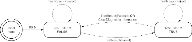
Figure D.1 — DTC status bit 0 testFailed logic
Table D.4 — DTC status bit 1 testFailedThisOperationCycle definitions
|
Bit
|
Description
|
Cvt: emission
|
CVT:
non- emission
|
Mnemonic
|
|
1
|
testFailedThisOperationCycle
|
M
|
C1
|
TFTOC
|
|
This bit shall indicate whether or not a diagnostic test has reported a testFailed result at any time during the current operation cycle (or that a testFailed result has been reported during the current operation cycle and after the last time a call was made to ClearDiagnosticInformation). Reset to logical ‘0’ when a new operation cycle is initiated or after a call to ClearDiagnosticInformation.
If this bit is set to logical ‘1’, it shall remain a ‘1’ until a new operation cycle is started.
|
|
Bit state after a successful ClearDiagnosticInformation service
|
logical ‘0’
|
|
Reset to a logical ‘0’ after a call to ClearDiagnosticInformation.
|
|
Bit state definition
|
Test Equipment Display Text
|
|
‘0’ = testFailed: result has not been reported during the current operation cycle or after a call was made to ClearDiagnosticInformation during the current operation cycle.
‘1’ = testFailed: result was reported at least once during the current operation cycle.
|
DTC test has not failed this operation cycle
DTC test failed this operation cycle
|
|
C1: Bit 1 (testFailedThisOperationCycle) is mandatory if bit 2 (pendingDTC) is supported. Bit 1 (testFailedThisOperationCycle) is user optional if bit 2 (pendingDTC) is not supported.
|
|
#
|
Pseudocode Operation
|
|
1.
2.
3.
4.
5.
6.
7.
8.
9.
|
IF (initializationFlag_TFTOC = FALSE) Set initializationFlag_TFTOC = TRUE Set testFailedThisOperationCycle = 0
Set lastOperationCycle = currentOperationCycle
IF ((currentOperationCycle != lastOperationCycle) OR (ClearDiagnosticInformation requested = TRUE)
Set lastOperationCycle = currentOperationCycle Set testFailedThisOperationCycle = 0
ELSE IF ((most recent test result = FAILED) AND (ClearDiagnosticInformation requested = FALSE))
Set testFailedThisOperationCycle = 1
|
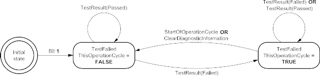
Figure D.2 — DTC status bit 1 testFailedThisOperationCycle logic
Table D.5 — DTC status bit 2 pendingDTC definitions
|
Bit
|
Description
|
Cvt: emission
|
CVT:
non- emission
|
Mnemonic
|
|
2
|
pendingDTC
|
M
|
U
|
PDTC
|
|
This bit shall indicate whether or not a diagnostic test has reported a testFailed result at any time during the current or last completed operation cycle. The status shall only be updated if the test runs and completes. The criteria to set the pendingDTC bit and the testFailedThisOperationCycle bit are the same. The difference is that the testFailedThisOperationCycle is cleared at the end of the current operation cycle and the pendingDTC bit is not cleared until an operation cycle has been completed where the test has passed at least once and never failed.
If the test was not completed during the current operation cycle, the status bit shall not be changed. For example, if a monitor stops running after a confirmed DTC is set, the pendingDTC must remain set = ‘1’. For an OBD DTC, a pending DTC is required to be stored after a malfunction is detected during the first driving cycle.
|
|
Bit state after a successful ClearDiagnosticInformation service
|
logical ‘0’
|
|
Reset to a logical ‘0’ after a call to ClearDiagnosticInformation.
|
|
Bit state definition
|
Test Equipment Display Text
|
|
‘0’ = This bit shall be set to 0 after completing an operation cycle during which the test was completed and a malfunction was not detected or upon a call to the ClearDiagnosticInformation service.
‘1’ = This bit shall be set to 1 and latched if a malfunction is detected during the current operation cycle.
|
DTC test has not failed during the current or last completed operation cycle
DTC test failed during the current or last completed operation cycle
|
|
#
|
Pseudocode
|
Operation
|
|
1.
|
IF (initializationFlag_PDTC = FALSE) Set initializationFlag_PDTC = TRUE Set pendingDTC = 0
Set failedOperationCycle = currentOperationCycle IF (ClearDiagnosticInformation requested = TRUE)
Set pendingDTC = 0
ELSE IF ((most recent test result = FAILED) AND (ClearDiagnosticInformation requested = FALSE))
Set pendingDTC = 1
Set failedOperationCycle = currentOperationCycle ELSE IF ((most recent test result = PASSED) AND (not
TestFailedThisOperationCycle)) AND (not TestFailedLastOperationCycle))
Set pendingDTC = 0
|
|
2.
|
|
3.
|
|
4.
|
|
5.
|
|
6.
|
|
7.
|
|
8.
|
|
9.
|
|
10.
|
|
11.
|
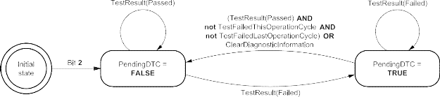
Figure D.3 — DTC status bit 2 pendingDTC logic
Table D.6 — DTC status bit 3 confirmedDTC definitions
|
Bit
|
Description
|
Cvt: emission
|
CVT:
non- emission
|
Mnemonic
|
|
3
|
confirmedDTC
|
M
|
M
|
CDTC
|
|
This bit shall indicate whether a malfunction was detected enough times to warrant that the DTC is stored in long-term memory (e.g. pendingDTC has been set = ‘1’ one or more times, depending on the DTC confirmation criteria).
A confirmedDTC does not always indicate that the malfunction is present at the time of the request (testFailed can be used to determine if a malfunction is present at the time of the request).
Reset to logical ‘0’ after a call to ClearDiagnosticInformation or after aging criteria have been satisfied (e.g. 40 engine warm-ups without another detected malfunction). Furthermore this bit is reset when the fault record associated with this DTC is overwritten by a newer DTC based upon vehicle-manufacturer-specific fault memory overflow requirements.
DTC confirmation and aging criteria are defined by the vehicle manufacturer or mandated by On-Board Diagnostic regulations.
|
|
Bit state after a successful ClearDiagnosticInformation service
|
logical ‘0’
|
|
Reset to a logical ‘0’ after a call to ClearDiagnosticInformation.
|
|
Bit state definition
|
Test Equipment Display Text
|
|
‘0’ = DTC has never been confirmed since the last call to ClearDiagnosticInformation or after the aging criteria have been satisfied for the DTC (or DTC has been erased due to fault memory overflow).
‘1’ = DTC confirmed at least once since the last call to ClearDiagnosticInformation and aging criteria have not yet been satisfied.
|
A confirmed DTC is not stored in the ECU.
A confirmed DTC is stored in the ECU.
|
|
#
|
Pseudocode Operation
|
|
1.
2.
3.
4.
5.
6.
7.
8.
9.
10.
11.
12.
13.
14.
15.
16.
17.
18.
19.
|
IF (initializationFlag_CDTC = FALSE) Set initializationFlag_CDTC = TRUE Set confirmedDTC = 0
Set confirmStage = INITIAL_MONITOR IF (confirmStage = INITIAL_MONITOR)
IF ((DTC confirmation criteria satisfied = TRUE) AND (ClearDiagnosticInformation requested = FALSE)) Set confirmedDTC = 1
Reset aging status
Set confirmStage = AGING_MONITOR ELSE
Set confirmedDTC = 0
IF (confirmStage = AGING_MONITOR)
IF ((ClearDiagnosticInformation requested = TRUE) OR (aging criteria satisfied = TRUE))
Set confirmedDTC = 0
Set confirmStage = INITIAL_MONITOR
ELSE IF ((most recent test result = FAILED) AND (ClearDiagnosticInformation requested = FALSE)) Reset aging status
ELSE
Update aging status as appropriate
|
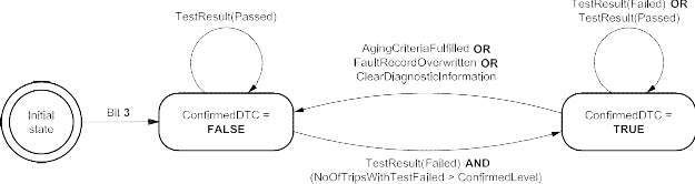
Figure D.4 — DTC status bit 3 confirmedDTC logic
Table D.7 — DTC status bit 4 testNotCompletedSinceLastClear definitions
|
Bit
|
Description
|
Cvt: emission
|
CVT:
non- emission
|
Mnemonic
|
|
4
|
testNotCompletedSinceLastClear
|
C2
|
C2
|
TNCSLC
|
|
This bit shall indicate whether a DTC test has ever run and been completed since the last time a call was made to ClearDiagnosticInformation. One (‘1’) shall indicate that the DTC test has not run to completion. If the test runs and passes or if the test runs and fails (e.g. testFailedThisOperationCycle = ‘1’), then the bit shall be set to a ‘0’ (and latched).
|
|
Bit state after a ClearDiagnosticInformation service
|
logical ‘1’
|
|
Reset to a logical ‘1’ after a call to ClearDiagnosticInformation.
|
|
Bit state definition
|
Test Equipment Display Text
|
|
‘0’ = DTC test has returned either a passed or failed test result at least one time since the last time diagnostic information was cleared.
‘1’ = DTC test has not run to completion since the last time diagnostic information was cleared.
|
DTC test completed since the last code clear
DTC test not completed since the last code clear
|
|
C2: Bit 4 (testNotCompletedSinceLastClear) and bit 5 (testFailedSinceLastClear) shall always be supported together.
|
|
#
|
Pseudocode Operation
|
|
1.
2.
3.
4.
5.
6.
7.
|
IF (initializationFlag_TNCSLC = FALSE) Set initializationFlag_TNCSLC = TRUE Set testNotCompletedSinceLastClear = 1
IF (ClearDiagnosticInformation requested = TRUE) Set testNotCompletedSinceLastClear = 1
ELSE IF ((most recent test result = PASSED) OR (most recent test result = FAILED))
Set testNotCompletedSinceLastClear = 0
|

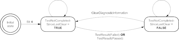
Figure D.5 — DTC status bit 4 testNotCompletedSinceLastClear logic
Table D.8 — DTC status bit 5 testFailedSinceLastClear definitions
|
Bit
|
Description
|
Cvt: emission
|
CVT:
non- emission
|
Mnemonic
|
|
5
|
testFailedSinceLastClear
|
C2
|
C2
|
TFSLC
|
|
This bit shall indicate whether a DTC test has ever been completed with a failed result since the last time a call was made to ClearDiagnosticInformation (i.e. this is a latched testFailedThisOperationCycle = ‘1’).
Zero (‘0’) shall indicate that the test has not run or that the DTC test ran and passed (but never failed). If the test runs and fails, then the bit shall remain latched at a ‘1’. Unlike confirmedDTC, this bit is not reset by aging criteria or due to an overflow of the fault memory.
|
|
Bit state after a successful ClearDiagnosticInformation service
|
logical ‘0’
|
|
Reset to a logical ‘0’ after a call to ClearDiagnosticInformation.
|
|
Bit state definition
|
Test Equipment Display Text
|
|
‘0’ = DTC test has not indicated a failed result since the last time diagnostic information was cleared.
‘1’ = DTC test returned a failed result at least once since the last time diagnostic information was cleared.
|
DTC test never failed since last code clear
DTC test failed at least once since last code clear
|
|
C2: Bit 4 (testNotCompletedSinceLastClear) and bit 5 (testFailedSinceLastClear) shall always be supported together.
|
|
#
|
Pseudocode Operation
|
|
1.
2.
3.
4.
5.
6.
7.
|
IF (initializationFlag_TFSLC = FALSE) Set initializationFlag_TFSLC = TRUE Set testFailedSinceLastClear = 0
IF (ClearDiagnosticInformation requested = TRUE) Set testFailedSinceLastClear = 0
ELSE IF ((most recent test result = FAILED) AND (ClearDiagnosticInformation requested = FALSE))
Set testFailedSinceLastClear = 1
|


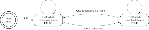
Figure D.6 — DTC status bit 5 testFailedSinceLastClear logic
Table D.9 — DTC status bit 6 testNotCompletedThisOperationCycle definitions
|
Bit
|
Description
|
Cvt: emission
|
CVT:
non- emission
|
Mnemonic
|
|
6
|
testNotCompletedThisOperationCycle
|
M
|
U
|
TNCTOC
|
|
This bit shall indicate whether a DTC test has ever run and been completed during the current operation cycle (or completed during the current operation cycle after the last time a call was made to ClearDiagnosticInformation).
A logical ‘1’ shall indicate that the DTC test has not run to completion during the current operation cycle. If the test runs and passes or fails then the bit shall be set (and latched) to ‘0’ until a new operation cycle is started.
|
|
Bit state after a successful ClearDiagnosticInformation service
|
logical ‘1’
|
|
Reset to a logical ‘1’ after a call to ClearDiagnosticInformation.
|
|
Bit state definition
|
Test Equipment Display Text
|
|
‘0’ = DTC test has returned either a passed or testFailedThisOperationCycle = ‘1’ result during the current drive cycle (or since the last time diagnostic information was cleared during the current operation cycle).
‘1’ = DTC test has not run to completion this operation cycle (or since the last time diagnostic information was cleared this operation cycle).
|
DTC test completed this operation cycle
DTC test not completed this operation cycle
|
|
#
|
Pseudocode Operation
|
|
1.
2.
3.
4.
5.
6.
7.
8.
9.
10.
11.
|
IF (initializationFlag_TNCTOC = FALSE) Set initializationFlag_TNCTOC = TRUE
Set testNotCompletedThisOperationCycle = 1 Set lastOperationCycle = currentOperationCycle
IF (ClearDiagnosticInformation requested = TRUE) Set testNotCompletedThisOperationCycle = 1
ELSE IF (currentOperationCycle != lastOperationCycle) Set lastOperationCycle = currentOperationCycle
Set testNotCompletedThisOperationCycle = 1 ELSE IF ((most recent test result = PASSED) OR
(most recent test result = FAILED))
Set testNotCompletedThisOperationCycle = 0
|

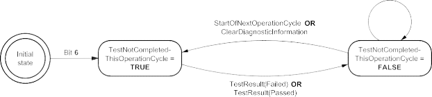
Figure D.7 — DTC status bit 6 testNotCompletedThisOperationCycle logic
Table D.10 — DTC status bit 7 WarningIndicator requested definitions
|
Bit
|
Description
|
Cvt: emission
|
CVT:
non- emission
|
Mnemonic
|
|
7
|
warningIndicatorRequested
|
M
|
U
|
WIR
|
|
This bit shall report the status of any warning indicators associated with a particular DTC. Warning outputs may consist of indicator lamp(s), displayed text information, etc. If no warning indicators exist for a particular DTC, this status shall default to a logic ‘0’ state.
Conditions for activating the warning indicator shall be defined by the vehicle manufacturer/implementation, but if the warning indicator is on for a given DTC, then confirmedDTC shall also be set to ‘1’ (with the exception described below).
|
|
Bit state after a successful ClearDiagnosticInformation service
|
logical ‘0’
|
|
Reset to a logical ‘0’ after a call to ClearDiagnosticInformation. Some ECUs may latch the failsafe strategy associated with a particular confirmed fault for the current operation cycle. If the warning indicator is still requested due to this latched failsafe following a call to ClearDiagnosticInformation, this bit shall not be cleared to a logical ‘0’. Rather, this bit shall remain set to logical ‘1’ until the failsafe strategy is no longer active (e.g. test is completed and passed). Additional reset conditions shall be defined by the vehicle manufacturer/implementation.
|
|
Bit state definition
|
Test Equipment Display Text
|
|
‘0’ = Server is not requesting warningIndicator to be active.
‘1’ = Server is requesting warningIndicator to be active.
|
DTC is currently not requesting warning indication
DTC is currently requesting warning indication
|
|
#
|
Pseudocode Operation
|
|
1.
|
IF (initializationFlag_WIR = FALSE) Set initializationFlag_WIR = TRUE Set warningIndicatorRequested = 0
IF (((ClearDiagnosticInformation requested = TRUE) OR (TestResult = Passed) OR (vehicle manufacturer or implementation-specific warning indicator disable
criteria
are satisfied)) AND (warning indicator not requested on due to latched failsafe for
particular DTC))
Set warningIndicatorRequested = 0
ELSE IF (((TestResult = Failed) AND warning indicator exists for the particular DTC) AND
((confirmedDTC = 1) OR
(vehicle manufacturer or implementation-specific warning indicator enable criteria are satisfied)))
Set warningIndicatorRequested = 1
|
|
2.
|
|
3.
|
|
4.
|
|
5.
|
|
6.
|
|
7.
|
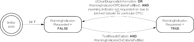
WarningIndicatorOnCriteriaFulfilled = warning indicator exists for particular DTC AND (confirmedDTC = 1 OR vehicle
manufacturer or implementation-specific warning indicator enable criteria are satisfied).
WarningIndicatorOffCritieriaFulfilled = TestResult(Passed) OR vehicle manufacturer or implementation-specific warning
indicator disable criteria are satisfied.
Figure D.8 — DTC status bit 7 WarningIndicator requested logic
-
Example for operation of DTC status bits
This example provides an overview on the operation of the DTC status bits in a two-operation cycle emissions-related OBD DTC. The Figure shows the handling for a two-operation cycle emissions-related OBD DTC. The handling can also be applied to non-emissions-related OBD DTCs and is shown here for general informational purposes.
NOTE In this example, the OBD server starts an operation cycle when the engine is started. The operation cycle ends (and the next operation cycle begins) the next time that the engine is started.
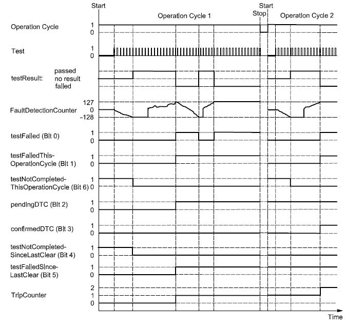
Figure D.9 — Example of a two-operation cycle emissions-related OBD DTC
-
DTCSeverityMask and DTCSeverity bit definitions
This subclause defines the mapping of the DTCSeverityMask/DTCSeverity parameters used with the ReadDTCInformation service. Every server shall adhere to the convention for storing bit-packed DTC severity information as defined in Table D.11 and Table D.12.
The severity information is reported in a one-byte value. Only the upper three bits (bit 7-5) of the one-byte value are used to represent the DTC severity information. The remaining bits (bit 4-0) have to be set to zero (0). Based on this the following bit coding applies to the three-bit DTC severity information contained in the one-byte DTCSeverity parameter.
Table D.11 — DTCSeverity byte definition
|
DTCSeverity byte
|
|
Bit 7
|
Bit 6
|
Bit 5
|
Bit 4
|
Bit 3
|
Bit 2
|
Bit 1
|
Bit 0
|
|
three-bit severity information
|
reserved by ISO 14229 — to be set to zero (0)
|
Table D.12 — DTC severity bit definitions (bit 7-5)
|
Bit 7-5
|
Description
|
Cvt
|
Mnemonic
|
|
000b
|
noSeverityAvailable
There is no severity information available.
|
M
|
NSA
|
|
001b
|
maintenanceOnly
This value indicates that the failure requests maintenance only.
|
M
|
MO
|
|
010b
|
checkAtNextHalt
This value indicates that the failure requires a check of the vehicle at the next halt.
|
M
|
CHKANH
|
|
100b
|
checkImmediately
This value indicates that the failure requires an immediate check of the vehicle.
|
M
|
CHKI
|
-
DTC functional unit definitions
The DTCFunctionalUnit is implementation-specific and shall be specified in the respective implementation standard.
-
DTCFaultDetectionCounter operation definition
The DTC fault detection counter operation for non-emissions-related servers is shown in Figure D.10.
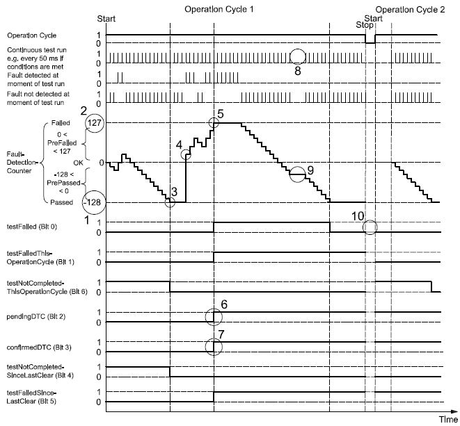
Key
-
test results = Passed
-
test results = Failed
-
test completes when it reaches minimum (-128) or maximum (127)
-
test run failure always causes fault detection counter to increment above 0 (so as not to double the fail detection time following a test complete with pass)
-
same as 3
-
pendingDTC bit is set because this example is for non-emissions-related server/ECU
NOTE Whether or not each DTC status bit is actually required to be supported or not is defined in D.2 and should not be inferred from this example.
-
same as 6
-
conditions are not met for test run (e.g. voltage out of range)
-
test did not run, therefore fault detection counter unchanged
-
vehicle manufacturer specific whether or not this bit is maintained between operation cycles or reset to zero
Figure D.10 — Example of DTCFaultDetectionCounter operation for non-emissions-related server
-
DTCAgingCounter example
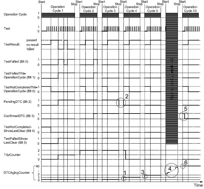
Key
-
DTCAgingCounter is incremented after completing an operation cycle in which test did not fail
-
pendingDTC is set to zero after an operation cycle in which the test completed and did not fail. In case an ECU does not support a power down sequence (i.e. is immediately shut off when the ignition is turned off) it will be unable to detect the end of the operation cycle. Therefore it is also valid to set the pendingDTC bit to zero at the beginning of the next operation cycle
-
DTCAgingCounter is incremented after completing an operation cycle in which test did not fail
-
DTCAgingCounter continues to increment because test is not failing during these operation cycles
-
confirmedDTC is set to zero when aging criteria is fully satisfied (e.g. DTCAgingCounter reaches a specific value)
-
DTCAgingCounter reaches a maximum value (e.g. 40) at which time the confirmedDTC bit is cleared
Figure D.11 — DTCAgingCounter example
Annex E
(normative)
Input output control functional unit data parameter definitions
E.1 InputOutputControlParameter definitions
Table E.1 — inputOutputControlParameter definitions
|
Hex
|
Description
|
Cvt
|
Mnemonic
|
|
00
|
returnControlToECU
This value shall indicate to the server that the client no longer has control over the input signal, internal parameter or output signal referenced by the inputOutputLocalIdentifier.
Number of controlState bytes in request: 0
Number of controlState bytes in possible response: depends on the dataIdentifier
|
U
|
RCTECU
|
|
01
|
resetToDefault
This value shall indicate to the server that it is requested to reset the input signal, internal parameter or output signal referenced by the inputOutputLocalIdentifier to its default state.
Number of controlState bytes in request: 0
Number of controlState bytes in possible response: depends on the dataIdentifier
|
U
|
RTD
|
|
02
|
freezeCurrentState
This value shall indicate to the server that it is requested to freeze the current state of the input signal, internal parameter or output signal referenced by the inputOutputLocalIdentifier.
Number of controlState bytes in request: 0
Number of controlState bytes in possible response: depends on the dataIdentifier
|
U
|
FCS
|
|
03
|
shortTermAdjustment
This value shall indicate to the server that it is requested to adjust the input signal, internal parameter or output signal referenced by the inputOutputLocalIdentifier in RAM to the value(s) included in the controlOption parameter(s) (e.g. set Idle Air Control Valve to a specific step number, set pulse width of valve to a specific value/duty cycle).
Number of controlState bytes in request: depends on the dataIdentifier
Number of controlState bytes in possible response: depends on the dataIdentifier
|
U
|
STA
|
|
04 - FF
|
ISOSAEReserved
This value is reserved by ISO 14229 for future definition.
|
M
|
ISOSAERESRVD
|
Annex F
(normative)
Remote activation of routine functional unit data parameter definitions
F.1 RoutineIdentifier definition
Table F.1 — routineIdentifier definition
|
Hex
|
Description
|
Cvt
|
Mnemonic
|
|
0000 - 00FF
|
ISOSAEReserved
This value shall be reserved by ISO 14229 for future definition.
|
M
|
ISOSAERESRVD
|
|
0100 - 01FF
|
TachographTestIds
This range of values is reserved to represent Tachograph test result values.
|
U
|
TACHOTI_
|
|
0200 - DFFF
|
vehicleManufacturerSpecific
This range of values is reserved for vehicle-manufacturer-specific use.
|
U
|
VMS_
|
|
E000 E1FF
|
OBDTestIds
This range of values is reserved to represent OBD/EOBD test result values.
|
U
|
OBDTI_
|
|
E200
|
DeployLoopRoutineID
This value shall be used to initiate the deployment of the previously selected ignition loop.
|
C
|
DLRI_
|
|
E201 – E2FF
|
SafetySystemRoutineIDs
This range of values shall be reserved by ISO 14229 for future definition of routines implemented by safety-related systems.
|
M
|
SASRI_
|
|
E300 - EFFF
|
ISOSAEReserved
This value shall be reserved by this document for future definition.
|
M
|
ISOSAERESRVD
|
|
F000 - FEFF
|
systemSupplierSpecific
This range of values is reserved for system-supplier-specific use.
|
U
|
SSS_
|
|
FF00
|
eraseMemory
This value shall be used to start the server's memory erase routine. The control option and status record format shall be ECU-specific and defined by the vehicle manufacturer.
|
U
|
EM_
|
|
FF01
|
checkProgrammingDependencies
This value shall be used to check the server’s memory programming dependencies. The control option and status record format shall be ECU-specific and defined by the vehicle manufacturer.
|
U
|
CPD_
|
|
FF02
|
eraseMirrorMemoryDTCs
This value shall be used to erase the server’s mirror memory DTCs.
|
M
|
EMMDTC_
|
|
FF03 - FFFF
|
ISOSAEReserved
This value shall be reserved by ISO 14229 for future definition.
|
M
|
ISOSAERESRVD
|
Annex G
(informative)
Examples for addressAndLengthFormatIdentifier parameter values
G.1 addressAndLengthFormatIdentifier example values
Table G.1 contains examples of combinations of values for the high and low nibble of the addressAndLengthFormatIdentifier. The following shall be considered.
-
Values, which are either marked as “not applicable” for the “manageable memorySize” or the “memoryAddress range”, shall not be used and shall be rejected by the server via a negative response message.
-
Values with an applicable “manageable memorySize” and “memoryAddress range” are allowed for this parameter.
Table G.1 — addressAndLengthFormatIdentifier example
|
Hex
|
Description
|
|
Bit 7-4 (high nibble) number of memorySize bytes
|
Bit 3-0 (low nibble) number of memoryAddress bytes
|
|
Bytes used for memorySize parameter
|
Manageable size
|
Bytes used for memoryAddress parameter
|
Addressable memory
|
|
00
|
not applicable
|
not applicable
|
not applicable
|
not applicable
|
|
01
|
not applicable
|
not applicable
|
1
|
256 byte – 1
|
|
02
|
not applicable
|
not applicable
|
2
|
64 KB – 1
|
|
03
|
not applicable
|
not applicable
|
3
|
16 MB – 1
|
|
04
|
not applicable
|
not applicable
|
4
|
4 GB – 1
|
|
05
|
not applicable
|
not applicable
|
5
|
1.024 GB – 1
|
|
06 … 0F
|
:
|
:
|
:
|
:
|
|
10
|
1
|
256 byte
|
not applicable
|
not applicable
|
|
11
|
1
|
256 byte
|
1
|
256 byte – 1
|
|
12
|
1
|
256 byte
|
2
|
64 KB – 1
|
|
13
|
1
|
256 byte
|
3
|
16 MB – 1
|
|
14
|
1
|
256 byte
|
4
|
4 GB – 1
|
|
15
|
1
|
256 byte
|
5
|
1.024 GB – 1
|
|
16 … 1F
|
:
|
:
|
:
|
:
|
|
20
|
2
|
64 KB
|
not applicable
|
not applicable
|
|
21
|
2
|
64 KB
|
1
|
256 byte – 1
|
|
22
|
2
|
64 KB
|
2
|
64 KB – 1
|
|
23
|
2
|
64 KB
|
3
|
16 MB – 1
|
|
24
|
2
|
64 KB
|
4
|
4 GB – 1
|
|
25
|
2
|
64 KB
|
5
|
1.024 GB – 1
|
|
26 … 2F
|
:
|
:
|
:
|
:
|
|
30
|
3
|
16 MB
|
not applicable
|
not applicable
|
|
31
|
3
|
16 MB
|
1
|
256byte – 1
|
|
32
|
3
|
16 MB
|
2
|
64 KB – 1
|
|
33
|
3
|
16 MB
|
3
|
16 MB – 1
|
|
34
|
3
|
16 MB
|
4
|
4 GB – 1
|
|
35
|
3
|
16 MB
|
5
|
1.024 GB – 1
|
|
36 … 3F
|
:
|
:
|
:
|
:
|
|
40
|
4
|
4 GB
|
not applicable
|
not applicable
|
|
41
|
4
|
4 GB
|
1
|
256 byte – 1
|
|
42
|
4
|
4 GB
|
2
|
64 KB – 1
|
|
43
|
4
|
4 GB
|
3
|
16 MB – 1
|
|
44
|
4
|
4 GB
|
4
|
4 GB – 1
|
|
45
|
4
|
4 GB
|
5
|
1.024 GB – 1
|
|
46 … FF
|
:
|
:
|
:
|
:
|
Bibliography
[1] SAE J1939-73, Recommended Practice for a Serial Control and Communications Vehicle Network Application Layer — Diagnostics
[2] ANSI/IEEE 754-1985, IEEE Standard for Binary Floating-Point Arithmetic
[3] ISO 16844-7, Road vehicles — Tachograph systems — Part 7: Parameters