Web LinkJump To
1. Out of the box
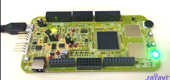
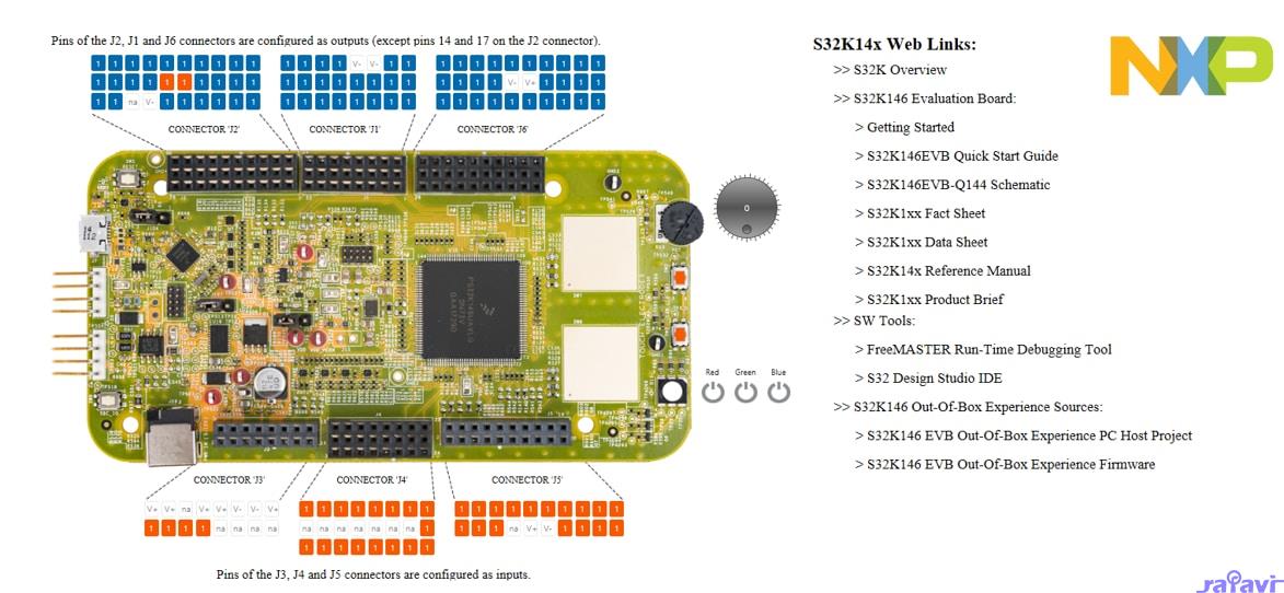
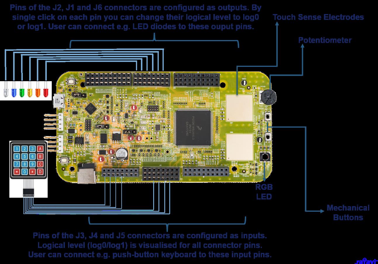
1.1 Get to know the S32K146 Evaluation Board for General Purpose
1.2 S32K146 Evaluation Board Features
1.3 Jumper Settings
1.4 HMI Mapping
Get Software
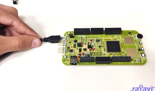
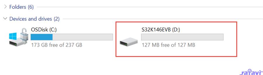
Plug It In
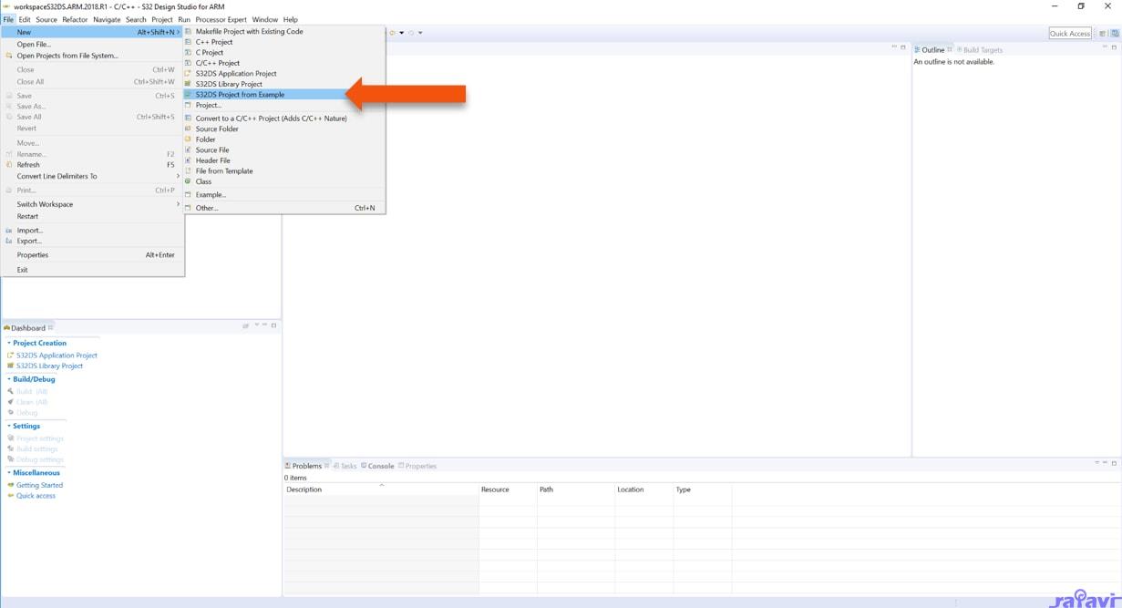
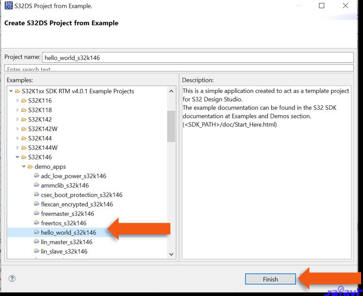
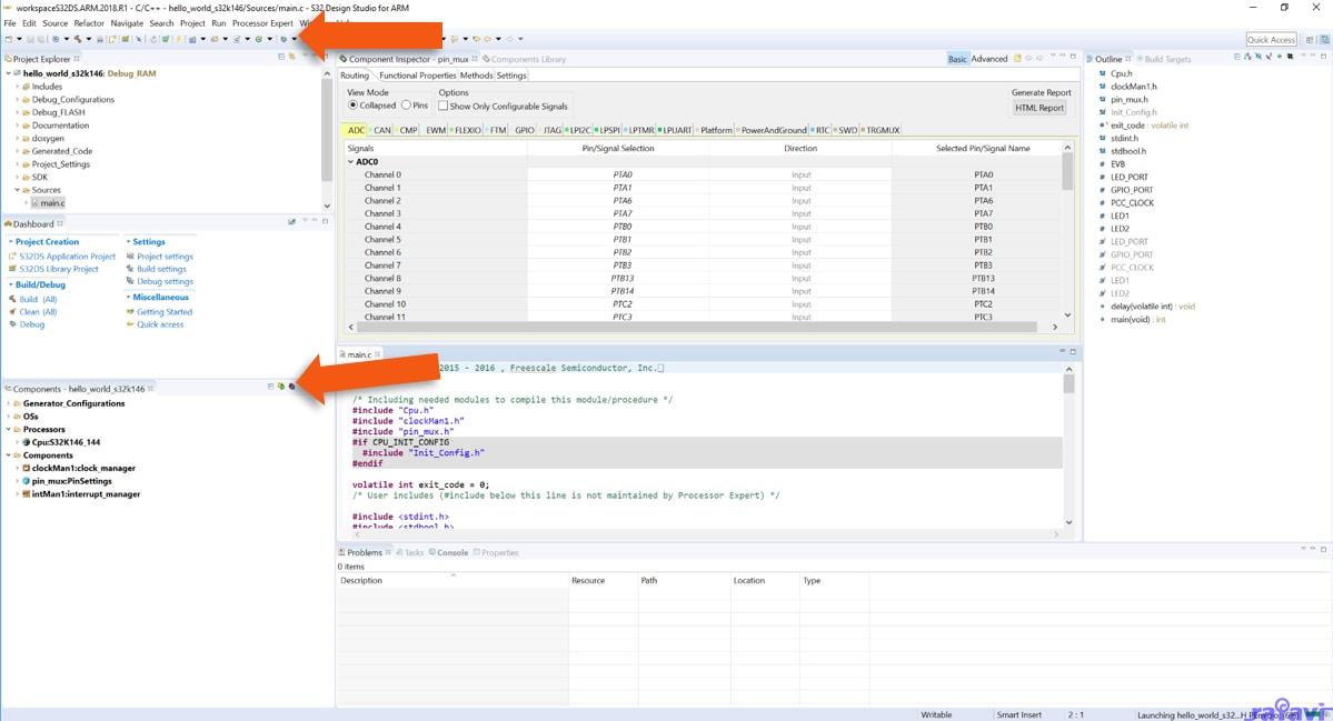
Build
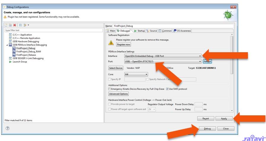
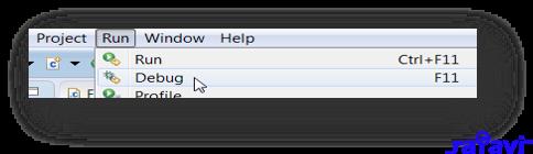
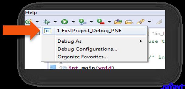
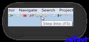
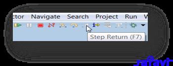
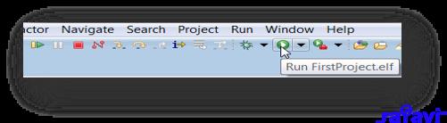
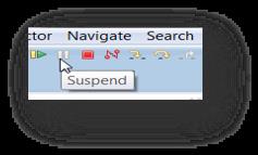
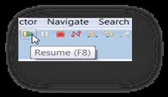
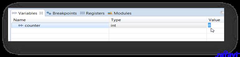
Debug
Out of the Box
1.1 Get to know the S32K146 Evaluation Board for General Purpose
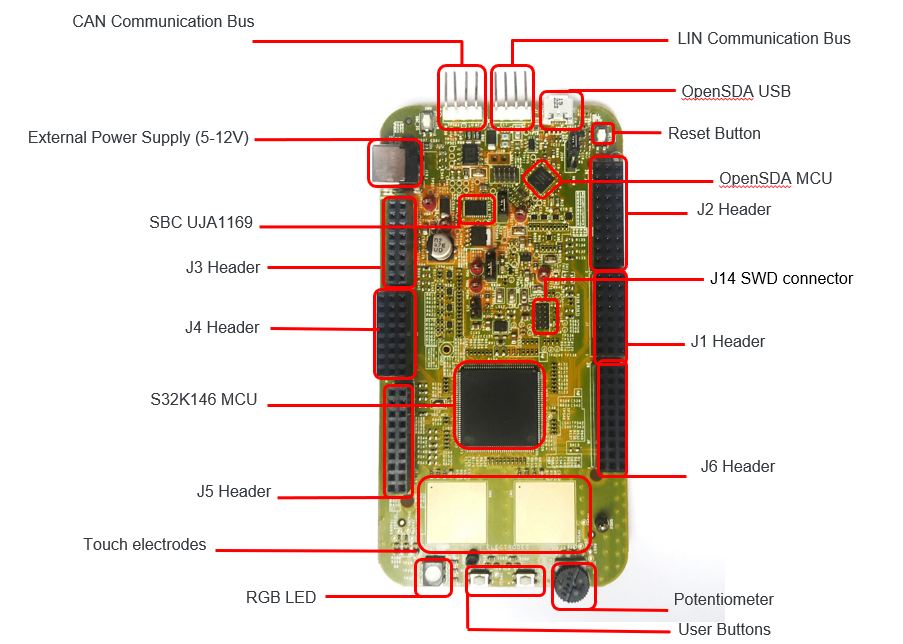
1.2 S32K146 Evaluation Board Features
Supports S32K146 144LQFP
Small form factor size supports up to n” x n”
Arduino™ UNO footprint-compatible with expansion “shield” support
Integrated open-standard serial and debug adapter (OpenSDA) with support for several industry-standard debug interfaces
Easy access to the MCU I/O header pins for prototyping
On-chip connectivity for CAN, LIN, UART/SCI
SBC UJA1169 and LIN phy TJA1027
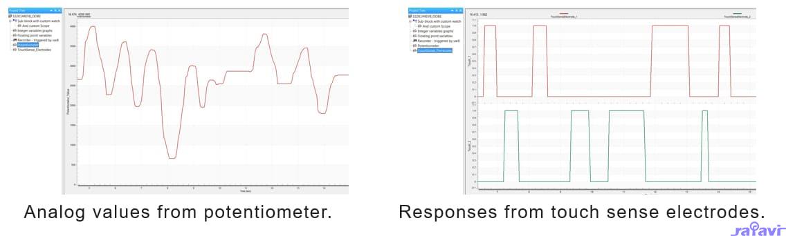
Potentiometer for precise voltage and analog measurement.
RGB LED
Two push-button switches (SW2 and SW3) and two touch electrodes
Flexible power supply options
o microUSB or
o external 12 V power supply
1.3 Jumper Settings
Jumper
Configuration
Description
J104
1-22-3 (Default
Reset signal to OpenSDA, use to enter into OpenSDA Bootloader mode.Reset signal direct to the MCU, use to reset S32K146.
J107
1-22-3 (Default
S32K146 powered by 12V power source.
S32K146 powered by USB micro connector.
J10
1-2
2-3 (Default)
VDD voltage is connected to 3.3 V.
VDD voltage is connected to 5 V.
1.4 HMI Mapping
Component
S32K146
Red LED
PTD15 (FTM0 CH0)
Blue LED
PTD0 (FTM0 CH2)
Green LED
PTD16 (FTM0 CH1)
Potentiometer
PTC14 (ADC0_SE12)
SW2
PTC12
SW3
PTC13
OpenSDA UART TX
PTC7 (LPUART1_TX)
OpenSDA UART RX
PTC6 (LPUART1_RX)
CAN TX
PTE5 (CAN0_TX)
CAN RX
PTE4 (CAN0_RX)
LIN TX
PTD7 (LPUART2_TX)
LIN RX
PTD6 (LPUART2_RX)
SBC_SCK
PTB14 (LPSPI1_SCK)
SBC_MISO
PTB15 (LPSPI1_SIN)
SBC_MOSI
PTB16 (LPSPI1_SOUT)
SBC_CS
PTB17 (LPSPI1_PCS3)
Get Software
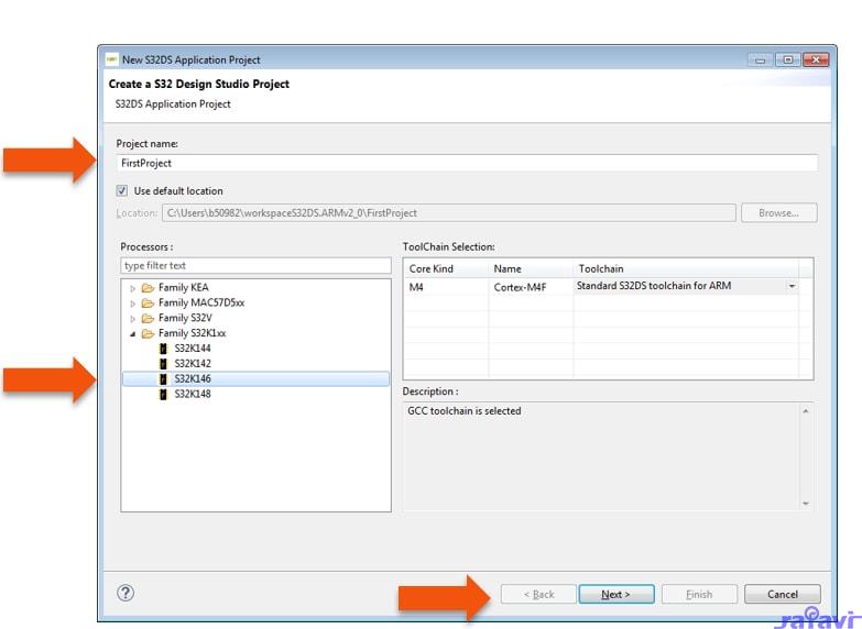
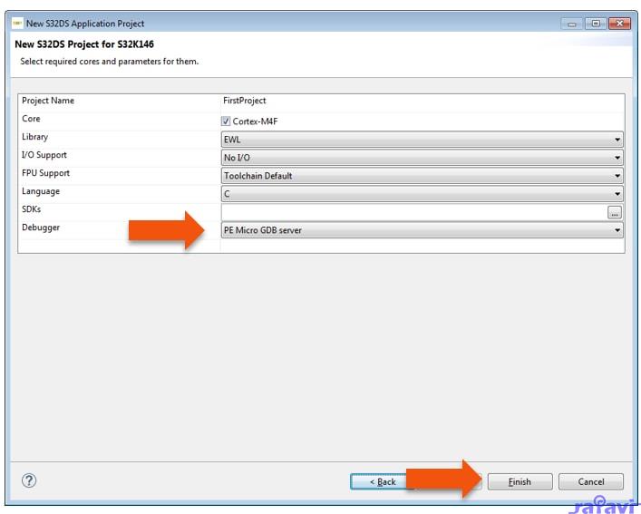
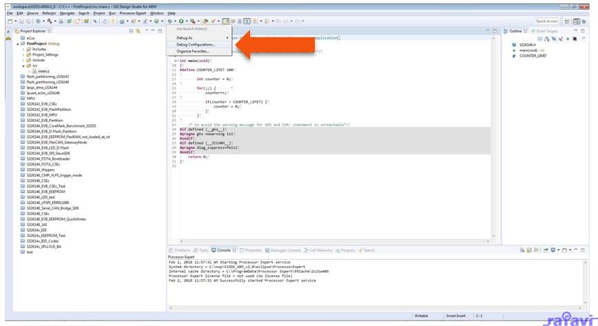
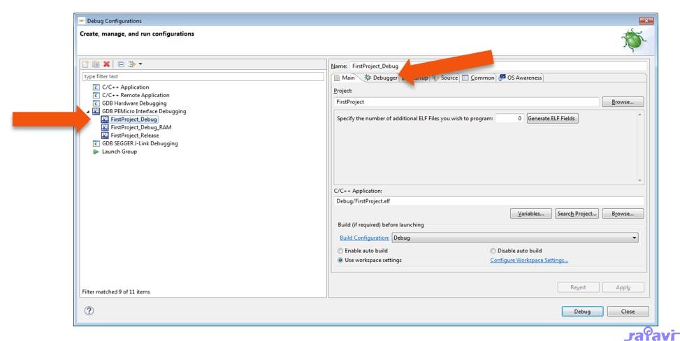
2.1 Integrated Development Environment (IDE)
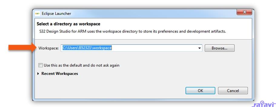
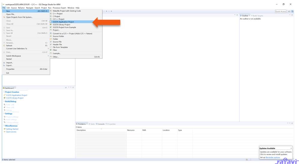
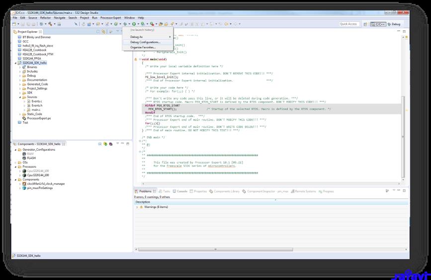
The S32 Design Studio for Arm® is a complimentary Integrated Development Environment (IDE) for automotive and ultra-reliable Arm-based microcontrollers that enables editing, compiling and debugging of designs.
DOWNLOAD S32DS FOR ARM
2....
1. Out of the box
1.1 Get to know the S32K146 Evaluation Board for General Purpose
1.2 S32K146 Evaluation Board Features
1.3 Jumper Settings
1.4 HMI Mapping
Get Software
Plug It In
Build
Debug
Out of the Box
1.1 Get to know the S32K146 Evaluation Board for General Purpose
1.2 S32K146 Evaluation Board Features
Supports S32K146 144LQFP
Small form factor size supports up to n” x n”
Arduino™ UNO footprint-compatible with expansion “shield” support
Integrated open-standard serial and debug adapter (OpenSDA) with support for several industry-standard debug interfaces
Easy access to the MCU I/O header pins for prototyping
On-chip connectivity for CAN, LIN, UART/SCI
SBC UJA1169 and LIN phy TJA1027
Potentiometer for precise voltage and analog measurement.
RGB LED
Two push-button switches (SW2 and SW3) and two touch electrodes
Flexible power supply options
o microUSB or
o external 12 V power supply
1.3 Jumper Settings
Jumper
Configuration
Description
J104
1-22-3 (Default
Reset signal to OpenSDA, use to enter into OpenSDA Bootloader mode.Reset signal direct to the MCU, use to reset S32K146.
J107
1-22-3 (Default
S32K146 powered by 12V power source.
S32K146 powered by USB micro connector.
J10
1-2
2-3 (Default)
VDD voltage is connected to 3.3 V.
VDD voltage is connected to 5 V.
1.4 HMI Mapping
Component
S32K146
Red LED
PTD15 (FTM0 CH0)
Blue LED
PTD0 (FTM0 CH2)
Green LED
PTD16 (FTM0 CH1)
Potentiometer
PTC14 (ADC0_SE12)
SW2
PTC12
SW3
PTC13
OpenSDA UART TX
PTC7 (LPUART1_TX)
OpenSDA UART RX
PTC6 (LPUART1_RX)
CAN TX
PTE5 (CAN0_TX)
CAN RX
PTE4 (CAN0_RX)
LIN TX
PTD7 (LPUART2_TX)
LIN RX
PTD6 (LPUART2_RX)
SBC_SCK
PTB14 (LPSPI1_SCK)
SBC_MISO
PTB15 (LPSPI1_SIN)
SBC_MOSI
PTB16 (LPSPI1_SOUT)
SBC_CS
PTB17 (LPSPI1_PCS3)
Get Software
2.1 Integrated Development Environment (IDE)
The S32 Design Studio for Arm® is a complimentary Integrated Development Environment (IDE) for automotive and ultra-reliable Arm-based microcontrollers that enables editing, compiling and debugging of designs.
DOWNLOAD S32DS FOR ARM
2....